Article

Nonlinear Thermo-Structural Analysis of Lightweight Concrete and Steel Decking Composite Slabs under Fire Conditions: Numerical and Experimental Comparison

by
Juan Enrique Martínez-Martínez
,
Felipe Pedro Álvarez-Rabanal
*,
Mar Alonso-Martínez
and
Juan José del Coz-Díaz
GICONSIME Research Group, University of Oviedo, 33204 Gijón, Spain
*
Author to whom correspondence should be addressed.
Appl. Sci. 2022, 12(18), 9306; https://doi.org/10.3390/app12189306
Submission received: 24 August 2022 / Revised: 10 September 2022 / Accepted: 13 September 2022 / Published: 16 September 2022

Abstract

:
Composite slabs with steel decking profiles are widely used in building construction. However, the literature on the fire resistance of lightweight concrete (LWC) composite slabs with steel decking is limited. In this work, the thermo-structural performance of LWC composite slabs with trapezoidal steel decking was studied under fire conditions. A total of 12 experimental fire tests were carried out using specimens of 160 mm thickness, 1120 mm width and 2030 mm length, in which nine composite slabs were made of LWC and the remaining three slabs were made of normal concrete (NC) to serve as a benchmark for comparison. All the samples were tested in a furnace following EN 13381-5, applying the standardized time–temperature curve and constant load. During the experimental tests, phenomena such as the vaporization of the free water inside LWC, debonding between steel decking and concrete and changes in material properties affected the thermo-structural performance of composite slabs. The test results show that the load-bearing capacity of lighter slabs does not assure the minimum structural behavior of R30. However, the lighter the concrete is, the lower the thermal transmittance, improving the slabs’ thermal performance under fire conditions. Advanced nonlinear numerical models were developed to predict the thermal and structural performance of the studied LWC composite slabs in terms of temperature and time-displacement. The influences of key factors such as vaporization, thermal strains and debonding were included using material properties and a thermal contact conductance interlayer. Finally, the nonlinear models and the experimental results were compared. The difference between the experimental and numerical values was less than 15%, showing that the numerical results were in good agreement with the experimental results. The results of this study also compared the performance of LWC composite slabs with the NC composite slabs, giving rise to interesting conclusions from a practical point of view.

1. Introduction

Buildings have a high impact on the environment and human health. Many studies, using LCA, have emphasized the beneficial environmental and economic impact of composite floor systems [1]. Furthermore, the current trend in the construction industry is to use lightweight solutions that facilitate a proper life cycle of materials [2]. To improve sustainability in the construction field, it is essential to reduce resource consumption, minimize environmental damage, diminish waste, reduce energy loss, and increase renewable energy use [3].
Composite slabs with steel decking profiles are widely used in building construction. These structural elements provide significant benefits such as speed of construction, weight reduction, stability, and sustainability. These systems take advantage of the compressive strength of concrete and the tensile strength of steel decking profiles. Thus, they guarantee satisfactory serviceability performance and strength requirements for commercial and residential buildings [4]. Concrete is usually reinforced to control the effects of shrinkage and to distribute the effect of concentrated loads. Reinforcement also increases the sagging moment capacity that helps to meet fire requirements [5]. Possible alternative solutions to traditional reinforcement are steel, polymer or glass fibers. The use of fibers reduces the formation of cracks caused by shrinkage and improves the tensile strength of concrete as well as its fire resistance [6].
LWC is a sustainable material with great benefits due to the significant reduction in self-weight compared to NC [7]. Many studies have been conducted to examine the structural performance of trapezoidal steel decking using LWC instead of NC at ambient temperatures [8,9,10]. Since LWC is a product of high-temperature sintering, which results in more internal holes inside the aggregate, it has good thermal stability, low thermal conductivity, and low thermal expansion coefficient [11]. Therefore, the LWC should have a better fire resistance performance than NC and thus the study of the fire resistance of LWC composite slabs is highly essential. However, few studies are currently available on the structural behavior of LWC composite slabs in fire [12].
The complex behavior of composite slabs under fire conditions and the high cost and time required in laboratory tests make numerical methods an interesting way to analyze this kind of problem. In the last decade, the use of FEM has been implemented to reveal the behavior of any structural element in a fire situation. The main challenges in a thermal numerical analysis are related to the heat transfer within the concrete slab. It is therefore necessary to properly define the variation of thermal properties of the concrete with temperature, the thermal contact between the steel decking and the concrete, and the effect of moisture transport [13].
Lamont [14] carried out parametric studies to investigate the most important factors affecting the temperature distribution within a slab. The results showed that the thermal conductivity of the concrete, the moisture content, and the convection value on the fire-exposed side were the most influential parameters. However, steel decking was not considered and aspects such as its geometry or the emissivity of the steel were not taken into account. Pantousa [15] simplified the thermo-mechanical model of composite slabs by sharing nodes between the steel decking and the concrete, assuming a continuity of temperature at the interface. Recent works emphasize the significance of development thermal analysis to address these problems. In 2017, Jian Jiang et al. [16], from the NIST, performed a numerical study based on detailed and reduced-order models of heat transfer in composite slabs. In addition, a parametric study using the detailed model was conducted to evaluate the effect of some parameters on temperature such as thermal boundary conditions, thermal properties of materials, and slab geometry. The temperature-dependent emissivity was also considered. The results of the proposed model for emissivity showed better agreement with experimental results than those calculated from the standard EN 1994-1-2 [17], hereafter referred to as Eurocode 4. Paulo et al. [18] developed and validated 3D finite element models to evaluate the thermal performance of composite slabs. This study included an air gap between the steel decking and the concrete to simulate the thermal effects on the slabs induced by the debonding between the steel decking and the concrete.
With regard to structural analysis, the main challenges include modelling the effects of material and geometric nonlinearities produced by the temperature. In addition, during fire exposure, the difference between the thermal expansion of steel and concrete causes debonding. Previous research works mention this phenomenon, which increases the thermal resistance in the interface between steel decking and concrete due to the air gap [18,19,20]. Most of the existing works define a thin layer between steel decking and concrete and assign thermal properties similar to air [21,22]. Piloto et al. [23,24] proposed new advanced 3D calculation models capable of simulating the debonding effect of steel decking from concrete topping. The models consider the existence of an air gap between these materials, acting as a thermal resistance on the temperature field through the thickness of the slab. The numerical results show a good approximation to the experimental results.
However, when a simultaneous solving of the heat transfer and stress analysis problems is required, it is not possible to ignore the mechanical performance of the contact between the steel decking and the concrete. This procedure causes non-realistic behavior, and nonlinear contact must be considered in the thermo-structural analysis [23].
The original contribution of this work is to experimentally validate a nonlinear finite-element modelling approach for thermo-structural analysis of LWC composite slabs in fire. In addition, the debonding effect between the steel decking and the concrete is considered. To simulate (debonding effect) the thermal gap conductance, a numerical model is developed, taking into account the effect of the temperature on thermal resistance at the contact interface. To validate this model, four types of concrete (three LWC and one NC) are cast in profile steel decking to manufacture pre-cast composite slabs. These composite slabs are tested in a furnace, applying a constant load and following the standards EN 13381-5 [25] and EN 1363-1 [26]. The main differences between LWC and NC composite slabs are also explained. The main objectives of this study include (a) examining the fire resistance of composite slabs made of steel decking profile and LWC, (b) developing thermo-structural numerical models, and (c) comparing experimentally validated advanced numerical models.

2. Experimental Study

This section describes the experimental studies conducted on twelve fire-unprotected composite slabs with identical profiled steel decking. Four types of concrete were studied: NC and three structurally different LWCs (LWC-1, LWC-2 and LWC-3). Three fire-tests were performed for each type of concrete. The geometry of the slab is first reported, followed by the properties of the materials. Then, the test procedure is described and finally the results are reported.

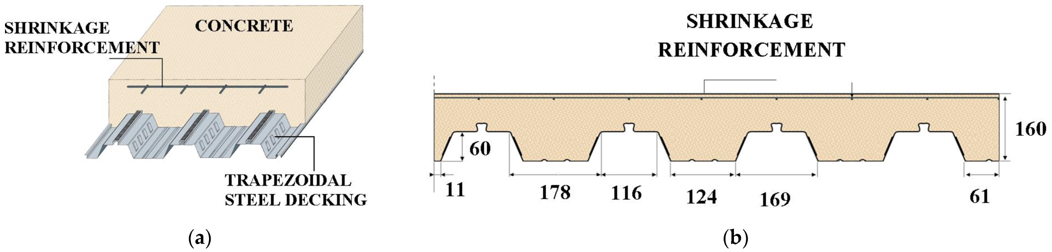
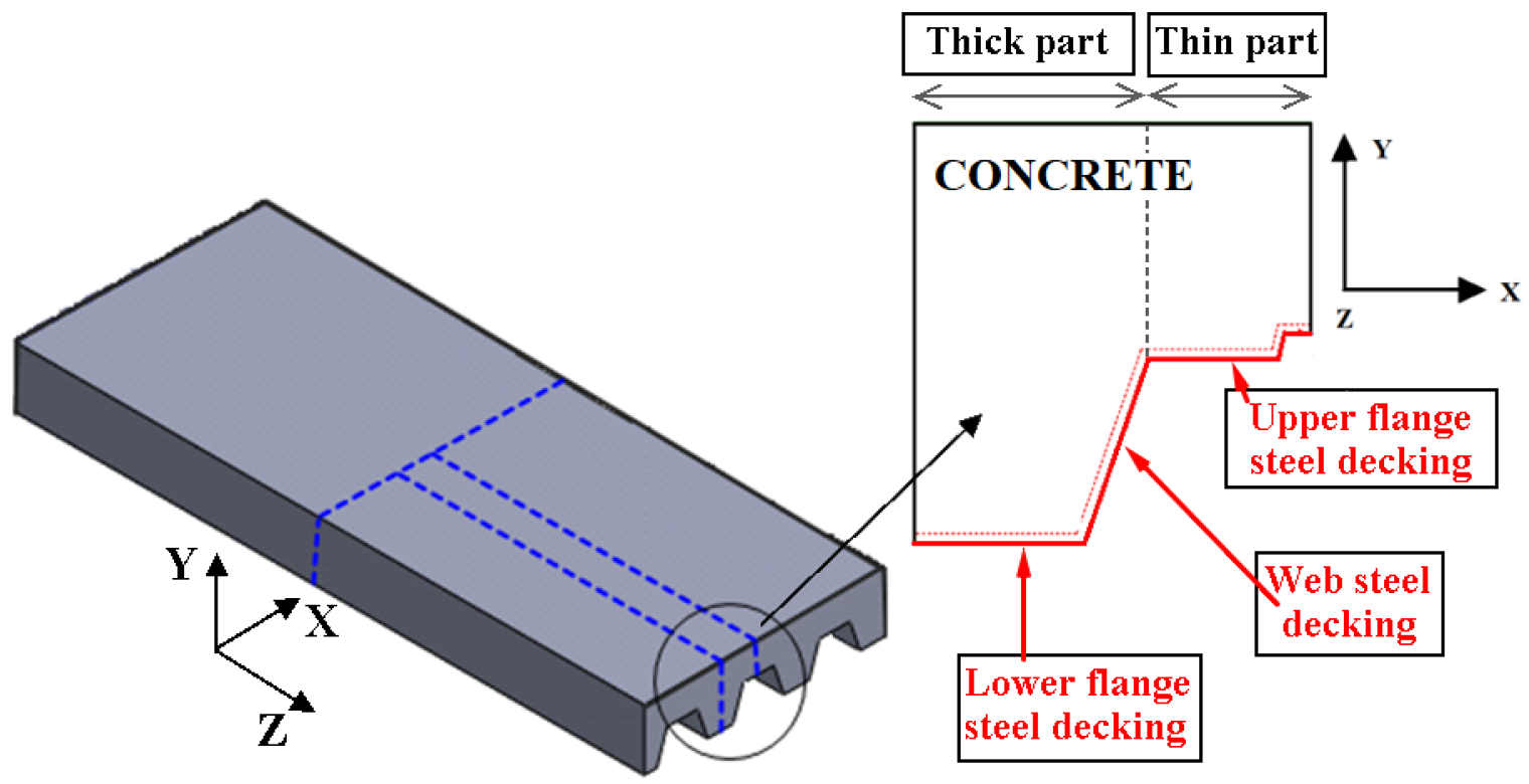
2.1. Description of the Slab Types

The same steel decking profile of 1 mm with embossments and three types of LWC as well as one type of NC, reinforced with polyolefin fibers, were used to manufacture unprotected composite slabs. A cross section of the composite slab profile is shown in Figure 1. In the upper part of the slabs, a reinforcement mesh with steel bars of 2 mm in diameter was used to minimize shrinkage cracks in the concrete. The profile steel decking has a total width of 1120 mm and 2030 mm length. The webs are inclined at a 71° angle and have several embossments to guarantee a good connection between the deck and the concrete. The shape of the profiles is shown in Figure 1.
Steel decking is made of cold-rolled steel. To study the mechanical properties of steel decking, three steel specimens were taken from the same batch of materials during the fabrication. Tensile tests following ISO 6892-1 [27] were carried out on these specimens and the averaged results are shown in Table 1.
Three types of LWC and one NC were manufactured for designing concrete slabs with compressive strength between 25 to 37 MPa. Portland cement (CEM II/A-V 42.5), siliceous aggregates, two sizes of expanded clay, water, and polyolefin fibers were used to manufacture concrete samples. In addition, siliceous aggregates with a diameter of 0–2 mm, ECF with diameters of 1–5 mm and a density of 430 kg/m3, and ECC with diameters of 2–10 mm and a density of 350 kg/m3 were used to manufacture the LWCs. In order to avoid shrinkage cracking, polyolefin fibers 48 mm in length and with a density of 910 kg/m3 were used. The mixing proportions used for the manufactured LWCs are shown in Table 2.
To achieve the compressive strength and elastic modulus of concrete, three cylinders of Φ100 mm × 200 mm for each concrete were cast and cured for 28 days. The average bulk density, compressive strength, and the elastic modulus of concrete are shown in Table 3. The modulus of elasticity was determined according to EN 12390 [28], while compressive strength follows UNE 83507 [29].
The thermal conductivity and specific heat of each LWC were measured in previous experimental studies [11]. The values at ambient temperature of thermal conductivity and specific heat are shown in Table 3.

2.2. Testing Procedure

All the composite slabs were tested with 640 days of age, and moisture was measured using a non-destructive concrete moisture meter CM 1700, with a content ranging from 6 to 10%. The fire tests were conducted in the furnace of the University of Oviedo [12]. The horizontal dimensions of the furnace are 1.20 m wide and 2.60 m long. The furnace was heated with three burners, which are fueled by light oil and operate with two-stage operation. The furnace temperature was measured with four K-type plate thermocouples placed inside the furnace. The readings of the thermocouples were used to adjust the temperature in the furnace to the ISO-834 standard fire curve [30]. The ambient temperature was close to 20 °C at the beginning of the fire resistance tests. More details of the static scheme and boundary conditions of the experimental procedure can be found in [12].
Before the fire exposure, the slabs were subjected to a designed 3-point bending test (see Figure 2c) for 15 min following EN 13381-5. Designed testing load was set corresponding to 60% of the maximum ambient bending strength. Previous experimental studies for this specific type of composite slab at ambient temperature were conducted to provide reference load carrying capacity [12]. Afterward, the furnace fire was ignited and controlled following the ISO-834 curve until the failure of composite slabs.
The temperature distribution in each slab was measured using sixteen K-type thermocouples (see Figure 2). Four of the thermocouples (1A-2B-3A-4B) were used to monitor the non-exposed surface temperature (see Figure 2). These thermocouples were used to verify the insulation criterion specified in Eurocode 4. The other twelve thermocouples, placed in groups of three (C: 7-10-14; D: 6-11-15; E: 8-9-13; F: 5-12-16), measured the temperature within the slab at different depths.
Thermocouples in zone C at a depth of 160 mm were placed in contact with the steel decking (see Figure 2). Likewise, thermocouples in zone D were placed in contact with the steel decking at the thinner part of the slab, at a depth of 100 mm (see Figure 2). Zone E and zone F measured the evolution of temperature within the concrete at a depth of 100 and 40 mm, respectively (see Figure 2). Two LVDTs were also placed on the top side at mid-span of the slab to obtain its maximum deflection, as shown in Figure 2.

2.3. Experimental Results

In this section, the main results of the thermal and structural tests are presented. Eurocode 4 evaluates the fire resistance of a composite slab using the following criteria: R, E and I. The R criterion is related to time in minutes for which an element can withstand a load during a fire. The E criterion is the time that an element prevents fire as well as smoke from going through it. Finally, the I criterion limits the temperature rise on the unexposed side.
The tests were finished when failure occurred. This was defined as the time when either: (a) it became inadvisable to allow slab deflection to develop further, due to the appearance of full-depth cracks; or (b) there was a significant drop in the mechanical resistance, and the hydraulic jack could no longer maintain the load level (exceed load-bearing capacity criterion, L/30 = 61 mm). The load-bearing capacity (R30) is fulfilled when a sample supports the load under fire conditions for 30 min, the minimum time established in the Eurocode 4.

2.3.1. Thermal Results

The influence of the thickness on the thermal performance of composite slabs was studied using two different zones: the thicker (zone A) and the thinner (zone B) parts. The temperatures measured at the thicker part and the thinner part are lower than the maximum increment of temperature on the non-exposed surface specified in Eurocode 4 to satisfy the insulation criterion. This criterion is considered not to be met if the unexposed surface temperature rise exceeds 140 °C on average or the maximum temperature exceeds 180 °C. All samples tested were below that temperature (see Figure 3).
The temperature on the exposed surface was measured in the trapezoidal steel decking, zones C and D (see Figure 2). The values obtained in these zones are much lower than the furnace temperature due to the heat sink effect of concrete slab above the steel decking and the vaporization of the free water in the interface between the steel and the concrete. The thermocouples placed at the steel decking reached 100 °C at 300 s after the beginning of the fire test. Figure 4 shows average temperatures at zones C and D for the four types of concrete studied. The differences in temperature in the steel decking between zones C and D are negligible.
Heat transfer in composite slabs with trapezoidal steel decking is not constant and depends on different factors, such as the angle of inclination of the steel decking [31]. The lower flange temperature was governed by the heat transfer through it. The web and upper flange of the decking have a slightly lower temperature than the lower flange due to the shielding effect of the rib. Because of the large heat capacity of the concrete, the temperature increase within the concrete slab is slow. The heat flux in zone E depends, therefore, on the normal flux gradient at the lower flange and on the normal flux gradient at the web. However, the heat flux in zone F depends only on the normal gradient in the upper flange. Therefore, temperatures in zone E are higher than those measured in zone F. The average temperatures measured in the concrete, in zone E (solid lines) and in zone F (dashed lines), are shown in Figure 5. The average temperature in zone E was obtained from thermocouples 8E-9E-13E (see Figure 2). The average temperature in zone F was obtained from thermocouples 5F-12F-16F (see Figure 2). The highest thermal conductivity of NC and LWC-2 causes higher temperatures at the end of the test in zone E. However, in zone F, NC reaches the highest value at the end of the test.
Figure 6a shows debonding between the steel decking and concrete slab after the test. This phenomenon occurs because steel and concrete have different thermal expansion rates at the same temperature. Debonding introduces a gap between the two elements, where water and vapor accumulate, affecting the heat transfer in the composite slab and reducing the rate of temperature rise at the bottom of the slab. A puddle of water driven out toward the top of the floor specimen was observed (see Figure 6b).

2.3.2. Mechanical Results

In all the tests carried out, deflection was measured over the fire test to ascertain how the temperature affects its value. When the load is applied, the central area withstands the greatest bending moment and consequently the maximum deflection. This means that cracks begin to appear in this area, becoming shorter in the supports. The cracks are distanced from each other, in a range of 100 to 180 mm, as shown in the Figure 6c.
The average vertical deflection for the four slabs is shown in Figure 7. The deflection measured for each type of composite slab is very similar. In all four cases, the deflection rises steeply for the first 50 s. Then, the increase drops off until 300 s, when it picks up again as shown in Figure 7. These marginal changes in the slope are related to the debonding process and crack growth. After 300 s, there is a continuous increase of deflection until the end of the tests. It is observed that the behavior of the lighter slabs (LWC-1 and LWC-2) is almost identical until 900 s. LWC-3 and NC also have similar structural behavior until 1300 s. The tests for LWC-1, LWC-2 and NC ended because the deflection exceeded the load-bearing capacity criterion (61 mm). After 1800 s, only LWC-3 and NC had a deflection lower than 61 mm.

3. Thermo-Structural Numerical Model

A 3D nonlinear FEM model was developed to carry out the numerical simulation for the performance of composite slabs under fire conditions. The coupled numerical modelling of the fire behavior of the composite slabs included two stages. Firstly, a transient thermal model was developed to obtain the temperatures of steel decking and concrete slab under standard fire conditions. Secondly, the temperatures of each body were used as input data for the structural model. Finally, the FEM model was validated against the test results, in terms of thermal and structural responses and failure modes.
Symmetry conditions were applied in X and Z directions in order to reduce both the size of the FEM model and the computational cost. The geometry in these simulations is a 16th of the total slab, as shown in Figure 8. In the experimental tests, the embossments of the steel decking increase the adhesion between steel and concrete. In the numerical models, the geometric modelling of the embossments made convergence difficult and increased the computational cost. Therefore, flat steel decking was used in this study to reduce the computational cost of the numerical model.
For this FEM analysis, an Intel Xeon Gold 6230 CPU with 256 GB RAM memory with 80 cores was used. The total CPU time was about 41 min for the thermal model and 30 min for each structural model.

3.1. Nonlinear Thermal FEM Model

To simulate thermal conduction in transient 3D thermal analysis, the profile steel decking was modelled with a 4-node shell heat transfer element (SHELL131) and the concrete slab was modelled with a 20-node solid heat transfer element (SOLID90) from the ANSYS software library [32]. The proposed numerical model took into account the nonlinear thermal contact between the steel decking and the concrete slabs, using surface-to-surface contact elements (TARGE170 and CONTA174) [32]. The mesh density was controlled to have a maximum element size of 5 cm with a uniform mesh. The thermal model had 86,094 nodes and 20,597 elements. The average element quality and the average orthogonal quality of the thermal FEM model were 0.9883 and 0.9928, respectively. The numerical model took into account the temperature-dependent thermal properties of all the materials. Nonlinear thermal properties of LWC, such as thermal conductivity and specific heat, were defined using the following procedures and experimental tests. Thermal conductivity of LWCs at ambient temperature was experimentally measured, as indicated in Table 2. Based on the Eurocode 4, nonlinear thermal conductivity was obtained using the following Equation (1).
k θ c = k 20 ° C θ c 1100 20 θ c 800   ° C k θ c = 0.5 θ c > 800   ° C
Heat transfer in porous LWC is greatly influenced by the moisture content [33]. Movement of water within the concrete is accompanied by significant energy transfer. This is associated with the latent heat of water and the heats of hydration and dehydration. It is known that the temperature increases at a slower rate above 100 °C. This effect is more significant for higher values of moisture content, constituting latent heat due to a vaporization process that consumes a lot of heat [11]. Thus, it leads to longer delays in the temperature rise within the concrete, and a plateau in the temperature history becomes evident for the moisture content of 7% or higher. After most of the moisture has evaporated (at temperatures exceeding about 150 °C), the temperature in the concrete rises more rapidly. This nonlinear effect of moisture vaporization is taken into account, modifying the specific heat in the range of 90 °C to 250 °C, following Equation (2).
c e ( θ c ) = 0.84   kJ / kgK 20 θ c 90   ° C c e ( θ c ) = 5   kJ / kgK     90 < θ c < 250   ° C c e ( θ c ) = 0.84   kJ / kgK 250   ° C θ c
Finally, temperature-dependent thermal properties in steel and NC such as specific heat and thermal conductivity are obtained from chapter 3 of Eurocode 4. It should be noted that the upper limit specified in Eurocode 4 is used for thermal conductivity of NC. Figure 9 shows the nonlinear thermal properties, both thermal conductivity and specific heat, for the three LWCs and NC.

Steel–Concrete Interaction

Debonding between the steel decking and the concrete slab was experimentally observed, as shown in Figure 6. This phenomenon caused a decrease in contact area at the interface and an increased resistance to heat flow. To take into account the increasing gap between steel decking and concrete, the thermal resistance at the contact interface was modified using APDL programming. APDL is a scripting language that is used to perform operations and parametric design analyses. Convective heat transfer occurs through the air gap, whereas conductive heat transfer occurs through metal contact points. If radiation heat transfer is neglected, the conductive heat transfer between two contacting surfaces is defined in Equation (3).
Q C C = k C C · ( θ c , T θ c , C )
Heat transfer at the interface between steel decking and concrete depends on two main parameters: the contact between materials and the gap [34]. Some researchers have suggested different constant values for kCC. Based on sensitivity analysis, Espinos et al. [35] suggested that kCC can be taken as a constant value of 200 W/m2K, while a different value of 38.1 W/m2K was used by Tao et al. [36]. However, the heat transfer at the interface between steel decking and concrete is expected to increase. Therefore, that increase in the gap alters its rheology, and kCC values should not be considered constant.
A parametric study was used to optimize kCC values. Several alternative methods were considered in an effort to better capture the heat input through the interface. The first option was to keep kCC constant and modify its value in order to provide additional heat input. However, following the recommendations of previous studies [19,33] that examined the influence of temperature in kCC, the most effective approach was found to be through its modification as a function of temperature. In this research, the nonlinear conductance value, kCC, was defined as a function of temperature in the steel decking, as shown in Table 4. These values were introduced using APDL in all contact surfaces. It should be noted that the current model for calculating kCC is based on the best fit to test results of composite LWC slabs. More work is required to measure kCC for composite LWC slabs with various parameters and to further evaluate the current model.

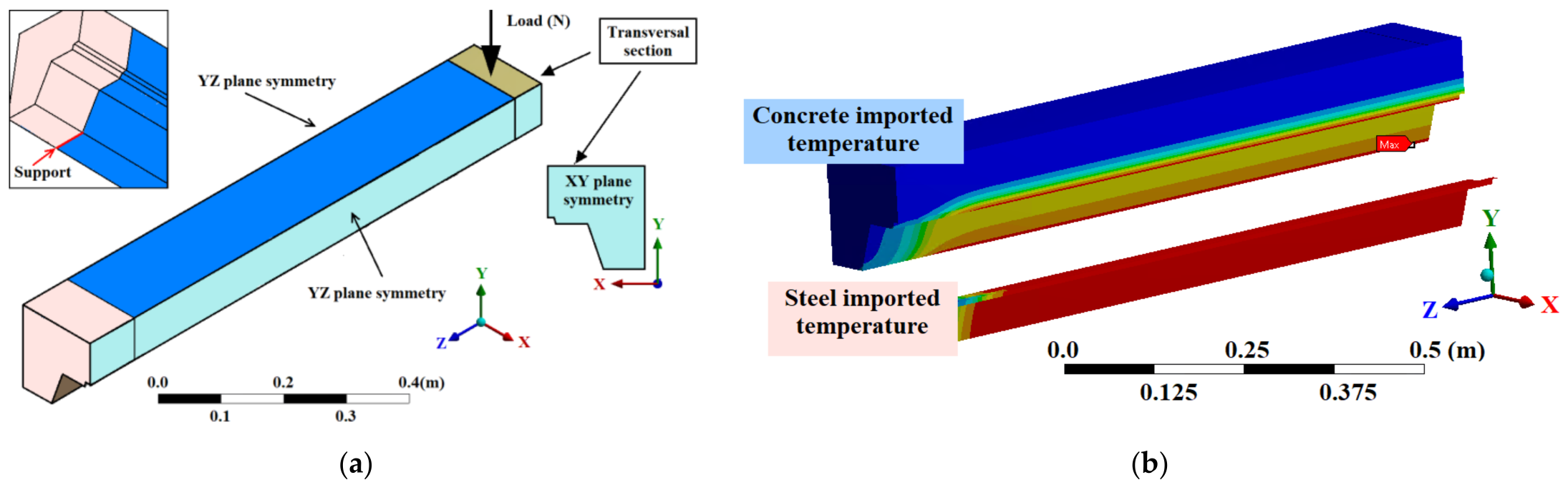
3.2. Nonlinear Structural FE Model

The numerical structural solution requires non-linear material behavior, as the values of mechanical properties of concrete and steel depend on temperature. The results from the nonlinear heat transfer analysis consisted of the temperature–time curves for all the nodes within the three-dimensional model, which were subsequently applied as thermal loading to the mechanical model. Different mesh controls were used to ensure a regular mesh. After thermal analysis, thermal elements SHEL131 and SOLID90 were converted into structural elements. The steel decking was meshed with 8-node shell element (SHELL281) and a maximum size of 5 mm. This element is suitable when large non-linear deformations occur and temperature conditions are used. The concrete was meshed using a 20-node solid element (SOLID186). This element is used when plasticity, creep and large deformations and deflections occur. The contact between the steel decking and the concrete was defined as bonded [31]. The structural model had 90,509 nodes and 20,604 elements, with an average element quality of 0.9887 and an average orthogonal quality of 0.9928.
The numerical model takes into account the plastic behavior of both materials, steel and concrete, using multilinear isotropic hardening laws. The design values for the steel decking were in accordance with experimental data previously reported [37] and followed the temperature dependence variation proposed by Eurocode 4. For all concretes, the stress–strain curves at ambient and elevated temperatures are based on Eurocode 4. For the case studied, the maximum experimental temperature reached was less than 400 °C.
When composite slabs are mechanically loaded and simultaneously heated, the overall measured strain concrete is assumed as an additive combination of different components [38]. The stress–strain curves included in Eurocode 4 consider deformation as a combination of elastic deformation, plastic deformation, and creep deformation. However, there is an additional component to determine the total deformation to which steel decking and concrete are subjected. This component is deformation due to thermal expansion and has different values for steel and concrete. In recent decades, there have been deeper studies of the rheological behavior of both concrete and steel at high temperatures [39].
The coefficient of thermal expansion of concrete varies with the type of cement and aggregates used, and the temperature reached. As the coefficients of thermal expansion of the various rocks that make up the aggregates and the cement paste are not the same, the variations in temperature cause differential thermal movements in the concrete mass, which can amplify its internal system of micro-fissures [40]. The deformation produced by temperature is shown in Equation (4).
ε t = ε t e + ε s + ε m f
The εt can be simplified according to Equation (5), in which εs and εmf are defined in the α coefficient [38]. This simplification was used in the coupled model developed in this study. Furthermore, as the maximum temperature measured within the concrete did not exceed 150 °C, the relationship between temperature and thermal expansion was defined as between 20 °C and 200 °C, as shown in Figure 10.
ε t = α × Δ T

3.3. Numerical Solution Schemes

An initial temperature of 20 °C is applied. On the non-exposed surface a constant convection coefficient of 9 W/(m2 K) as well as radiation effect are applied following Eurocode 1 [41]. The heat flow exchange between the fire-exposed surface of the steel decking and the fire environment takes into account convection and radiation heat transfer as Eurocode 1 defines. The steel decking is subjected to standard fire conditions. Owing to the obstruction to direct fire exposure caused by the waves of the steel decking, two convection coefficients are used: 25 W/(m2 K) for the web and 15 W/(m2 K) for the lower and the upper flange, respectively [42]. Profile steel decking is usually made of galvanized cold-formed steel. The emissivity value of 0.7 specified in Eurocode 4 does not consider the lower emissivity value of the zinc used in the galvanization. Therefore, in this work, a constant emissivity value of 0.4 is used, following previous works [13].
The thermal numerical analysis was divided into 160 steps, which were carefully set to reduce convergence difficulties. The duration of each load step was set individually. To set the duration of each step, two conditions were established: (1) a variation of 30 °C between consecutive steps and (2) a maximum duration of 20 s for each step. The environmental temperature for each step was equal to the furnace temperature during the experimental tests.
A sequential thermo-structural model was used to analyze the stress distribution of specimens under fire conditions. The temperature field results of the thermal analysis were used as the predefined field of the thermo-structural analysis (see Figure 11b). In the same position where the support is placed, the vertical displacement is constrained, and the load is applied at the top surface of the slab (see Figure 11a).
Due to the complexity of the analysis increasing as the temperature rises, three loading steps were used for solving structural numerical analysis. These load steps gradually increase the load to make the convergence of the model easier.
For this purpose, the first load step has a minimum step of 0.001 s and a maximum step of 0.1 s. In the second load step, the minimum step time defined is 0.001 s and the maximum is 0.05 s. In the third load step, the minimum time defined is 0.001 s and the maximum time is 1 s.

3.4. Numerical Results

The effect of nonlinear thermal properties on temperature distribution in the concrete is shown in Figure 12. LWC-3 has a lower thermal conductivity than other LWCs. This causes a region of greater thickness where the temperatures are lower than those obtained in LWC-1 and LWC-2. The temperature evolution for LWC-1 and LWC-2 slabs is very similar because they have thermal conductivities with very close values. NC shows more thermal transference than LWCs. The concrete temperatures for trapezoidal slabs are influenced not only by the thermal conductivity but also by the moisture content. Higher values of thermal conductivity and lower values of moisture content imply higher average temperatures in the concrete slab. Therefore, for correctly predicting the temperatures for the trapezoidal slabs, it is essential to incorporate the effect of the concrete’s thermal conductivity.
Figure 13 shows the vertical displacement of the FEM model for each type of concrete at 1800 s. In all the numerical models, the effect of temperature on the mechanical properties of the composite slab is applied. The variation of stress and the vertical displacement of the neutral axis as the time increases are checked for all the numerical models. The lighter concretes, identified as LWC-1 and LWC-2, have very similar structural behavior during the tests. However, LWC-3, which has a higher density, behaves very similarly to NC.

4. Numerical and Experimental Comparison

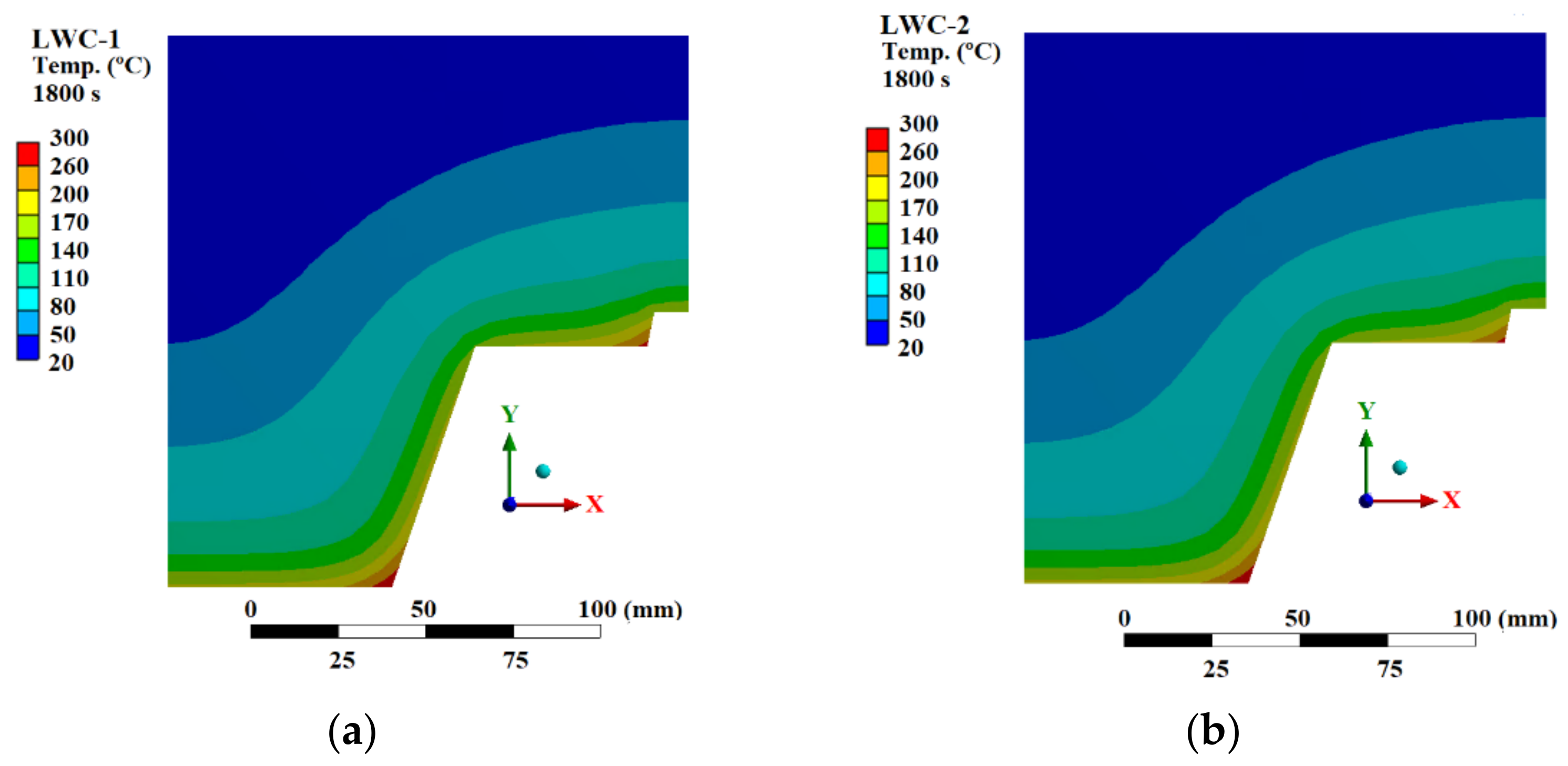
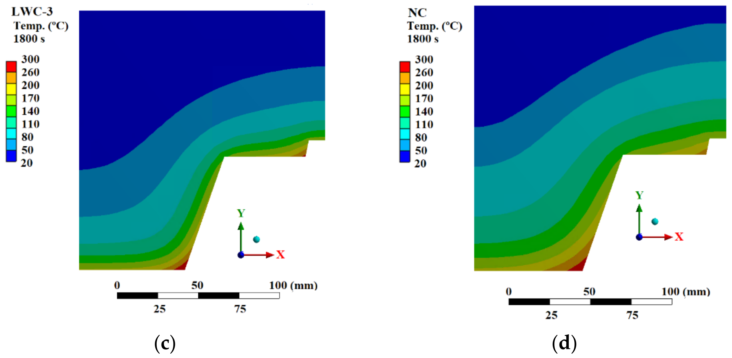
4.1. Thermal Comparison

To provide cross-sectional temperatures and to validate the thermal numerical model, six coordinate systems were created at the same points where the thermocouples were placed in the experimental tests (A, B, C, D, E, F zones).
Figure 14 shows a temperature comparison between the experimental tests and the numerical simulation at the steel decking. The temperature measured in the interface of steel decking and concrete is very similar in the four numerical models, with the temperature in NC being slightly lower in the first time steps. Figure 14 shows that the numerical model can qualitatively represent the physical phenomena in zones C and D of the slabs. Initially, despite the numerical model temperature evolution being slower than the laboratory results, it is possible to simulate the experimental heat transfer phenomenon. The increase in temperature in the experimental results shows a slope reduction after 450 s due to the endothermic process of free water vaporization. Numerical models simulate that effect by changing the slope at around 100 °C. At the end of the numerical simulation, around 1300 s, there is a large divergence between the experimental and numerical results, due to the absence of free water in the composite slab at the end of the endothermic process.
The temperature within the concrete is highly influenced by its thermal conductivity. The temperature results in the numerical model in zones E and F are shown in Figure 15. In these zones, the numerical and experimental temperatures are in good agreement for the first 300 s. After that, the movement and diffusion of water, caused by vaporization, makes it difficult for the numerical models to follow the experimental values. For zone E, although the numerical models for LWC-1 and LWC-2 (see Figure 15a) are unable to simulate the rapid increase in temperature that occurs in the interval from 300 s to 500 s, they can replicate the trend of temperature increase correctly. This difference between the numerical and experimental results is due to part of the free water mass escaping from the specimen at the heating surface, with the rest moving to the inner core characterized by a lower temperature, where vapor condensates into water. It is found that the existing model does not realistically account for pore structure, and thus is not capable of properly predicting thermal conductivity as a function of liquid saturation. However, the numerical model quantitatively simulates the thermal behavior for LWC-3 and NC slabs in zone E during the entire thermal analysis (see Figure 15b). Figure 15 also shows that the numerical results in zone F are closer to the experimental results.
On the non-exposed side, the numerical model results in Figure 16 show the evolution of the temperature as a function of thickness and time, in zones A and B. In addition, the numerical results range from 20 to 32 °C, inside the maximum and minimum limits of the experimental results, respectively. As shown in Figure 16, the insulation criterion is fulfilled.
The thermal flux at the thin part of the slab (zones B and F) is one-directional and perpendicular to the upper flange of the steel decking. The thermal flux at the thick part (zones A and E) is perpendicular to the lower flange and the web of the steel decking. The evolution of temperature for zones B and F in the numerical models is close to that measured experimentally in zones A and E.

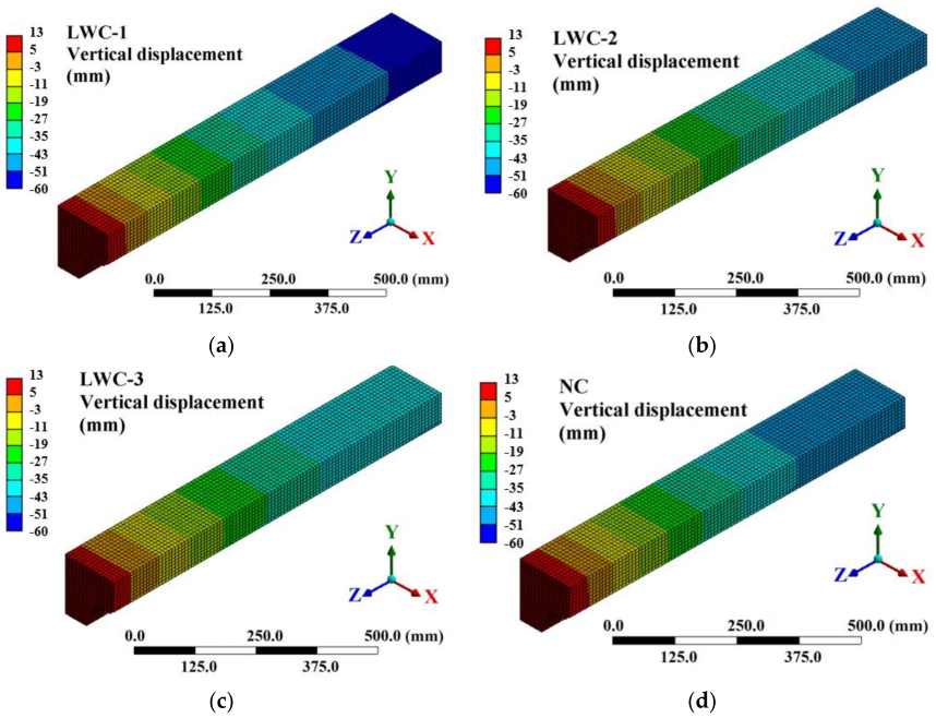
4.2. Structural Comparison

Figure 17 shows a comparison of the measured central deflection of the slab against deflections predicted using the coupled thermo-structural model. The figure shows that the behavior established between tests and numerical models is very similar.
Here, the percentages of error (%) between experimental and numerical analyses are compared. The difference between the experimental and numerical values, in each of the simulations, is less than 15% in most of the cases analyzed, as shown in Table 5. When steel reaches a critical temperature between 450 °C and 800 °C, it loses its strength and stiffness. This critical temperature depends on factors such as the type of steel, the manufacturing process, and the treatments to which it has been subjected. Due to the range in which this physical phenomenon occurs, simulating this behavior is difficult. For this reason, the main differences between the experimental values and the numerical values occur between 200 and 700 s. At this point, the ambient temperature in the furnace is between 518 °C and 700 °C. In addition, at this temperature steel decking and concrete slab stop working together.
It should be mentioned that the above findings are based on several assumptions, and the validity of the proposed model is limited to the experimental data. Limitations still exist in this study, and further research may be needed. First, mechanisms of mass transport within LWC create difficult conditions that are hard to simulate due to their complexity. Second, temperature distributions obtained from thermal analysis influence the structural response through thermal expansion and through degradation of material stiffness and strength. Therefore, it is necessary to take into account the heating process at the same time as the structural response to properly capture the effects of material and geometric nonlinearities at large deformations. Notwithstanding these limitations, the results in this study can be used to explain some experimental observations, such as the debonding.

5. Conclusions

In the present paper, the thermo-structural behavior of LWC in composite slabs with profile steel decking subjected to fire and a constant load were studied. Extensive experimental tests and numerical analysis were performed and, based on the respective experimental and numerical results, the following conclusions can be drawn:
Experimental results:
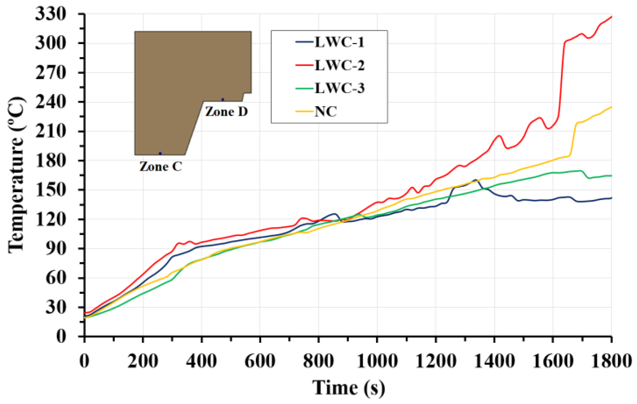
  • The measured temperatures on the steel decking profile are lower than the ISO 834 curve. This phenomenon is due to free water vaporization, and the debonding effect that introduces an air gap between the concrete and the steel decking profile.
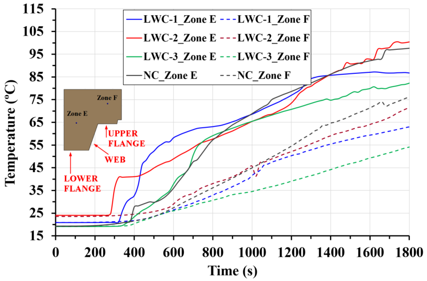
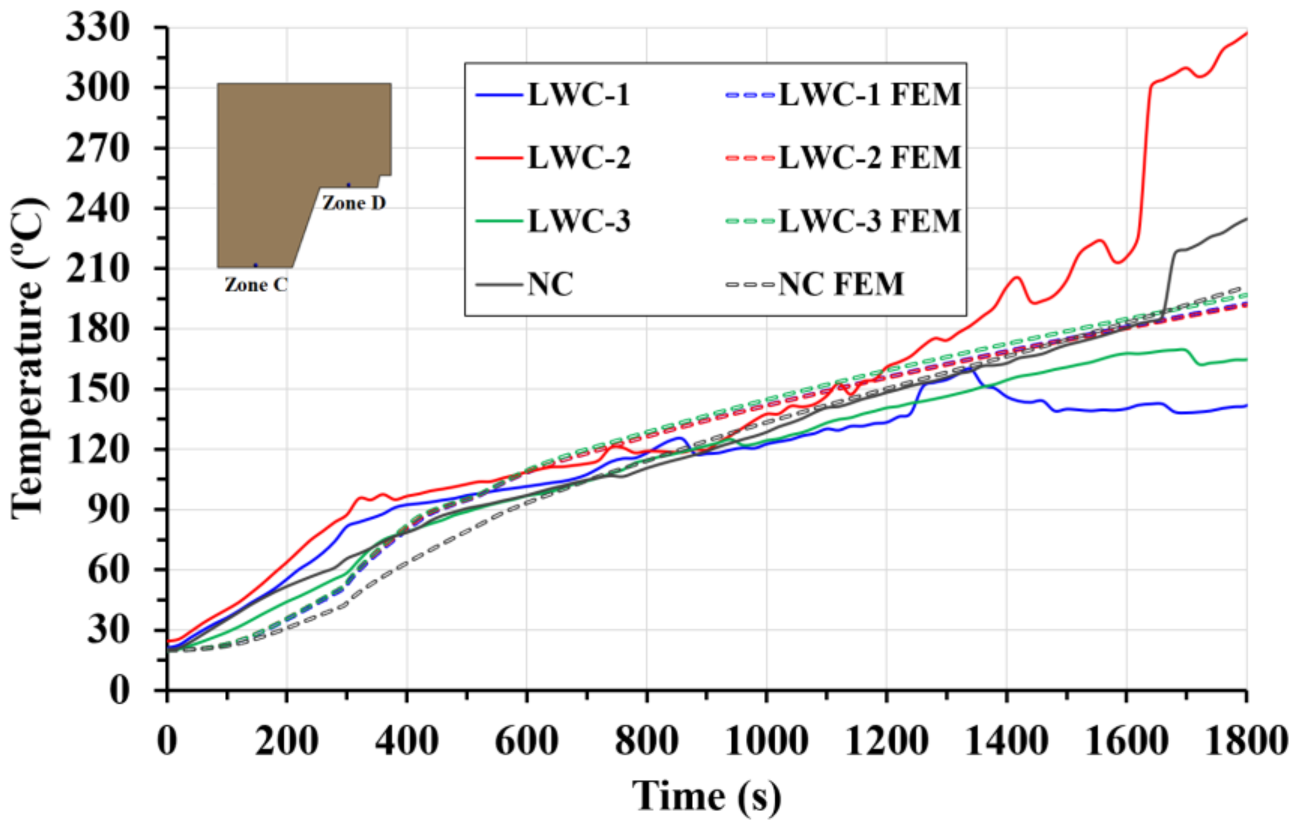
  • Concrete contains water that vaporizes at temperatures above 100 °C. In this work, the measured temperatures on the concrete show a non-constant increase and a plateau at 100 °C. This is caused by the vaporization process of the free water, which is an endothermic reaction and consumes energy, slowing down the heating up of the concrete.
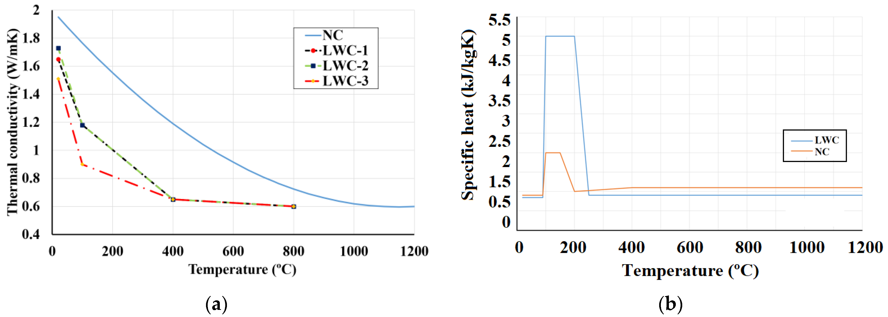
  • The thermal properties (thermal conductivity, specific heat) of concrete, the moisture content and the porosity affect the increase in temperature in the slab. Furthermore, the complex heat transfer phenomenon due to the vaporization in LWC slabs causes a greater distortion. This effect is mainly due to the porosity of the material, which is directly related to its moisture content.
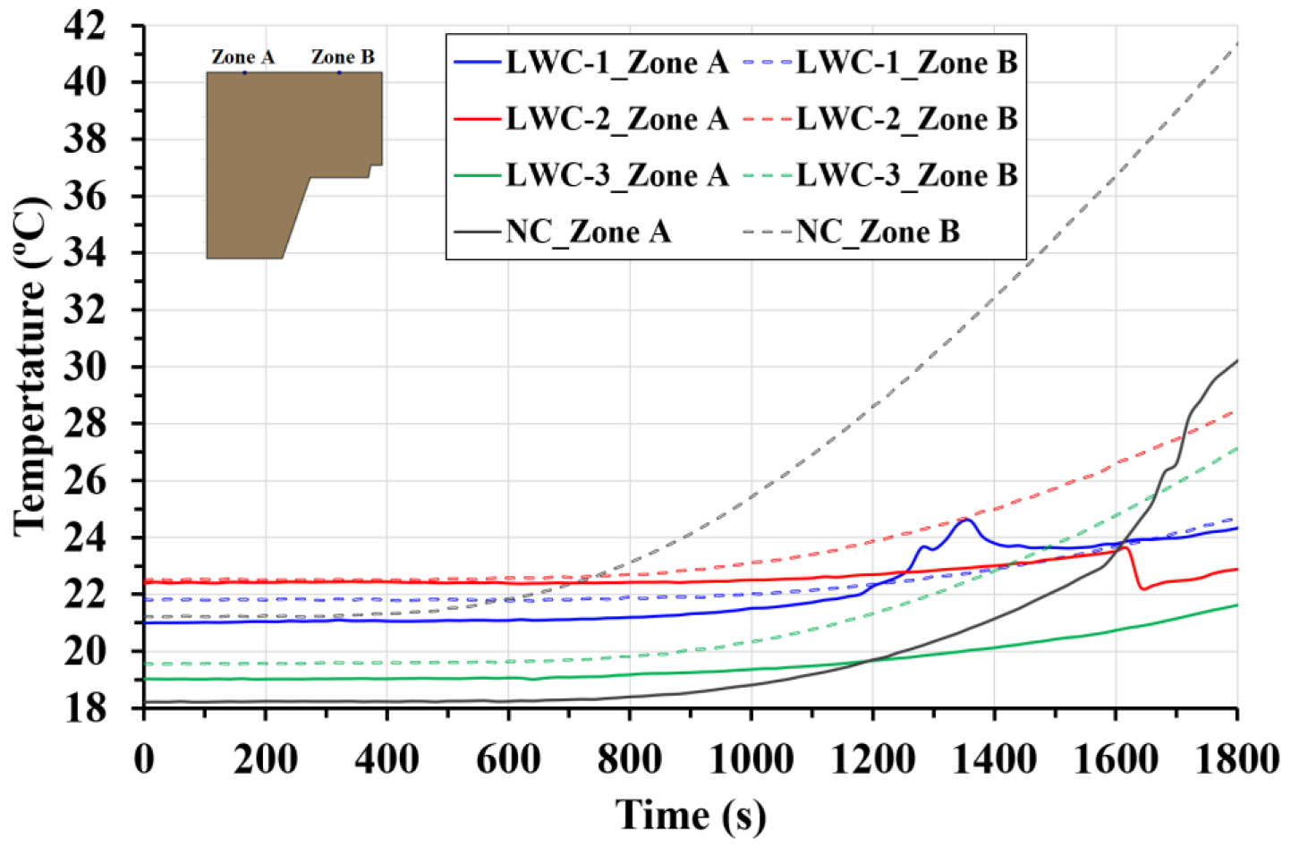
  • The higher moisture content of LWC composite slabs causes the measured temperature in LWC composite slabs to be lower than NC. Therefore, LWC composite slabs have lower heat transfer under fire conditions than NC.
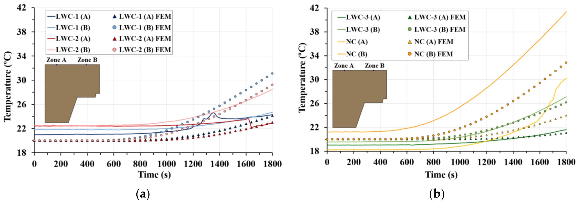
  • The insulation criteria of the composite slab and the influence of the trapezoidal shape is studied on the non-exposed surface. The temperature variation between the thinner and thicker part is lower than 15 °C. Therefore, based on the temperature measured, the insulation and integrity criteria are met for all the samples.
  • The experimental results show that there is debonding between the steel decking and the concrete slab. This phenomenon introduces a gap between both materials; thus, the heat transfer in the composite slab is influenced and the pressure in the internal concrete pores is reduced. Spalling is not observed in any of the tests carried out. It can be concluded that the steel decking prevents direct fire exposure to the concrete core and acts as a barrier to the expansive effect of spalling on this type of structural element.
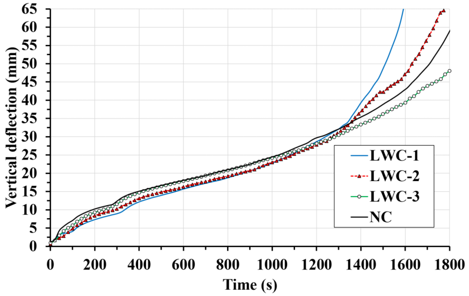
  • In general, the vertical deflection under fire conditions has three stages. The first stage is caused by the thermal expansion and reduction of the mechanical properties of steel. The second stage involves the load transfer to the concrete. Finally, the slab collapses.
  • Although the deflection measured in all the slabs is very similar, the load-bearing capacity (R30) is reached only for LWC-3 and NC. It is observed that the structural behavior of the lighter slabs does not accomplish the minimum load-bearing capacity of 30 min. To achieve the load-bearing capacity, two possible solutions can be used. First, composite slabs should be reinforced to ensure the minimum value of R30 is reached. Second, active fire protection elements can be used on the trapezoidal steel decking so that the temperature increase in the steel decking is slowed down and its mechanical properties are maintained for longer. A combination of the two solutions is also possible.
Numerical simulation:
  • ANSYS Workbench Mechanical can link a thermal analysis to a structural analysis, sharing Engineering Data, Geometry and Model directly. When directly linked, bodies in the structural model cannot be suppressed independently of the thermal analysis. When the same mesh is used, temperature mapping is usually simple. If the thermal model has finite contact conductance for a contact pair, a temperature drop can occur across the pair, and users should ensure that temperatures from one side of a contact pair do not end up on the other side. An identical mesh helps to avoid convergence issues.
  • A bonded contact with variable thermal properties was used in the numerical model because the embossments of the steel decking significantly reduce the sliding between the concrete and the steel decking. As shown in Section 3.1, numerical and experimental results are in good agreement.
  • The numerical models developed simulate the effect of the endothermic process of free water vaporization, showing slope changes around 100 ºC. At the end of the FEM model, around 1500 s, there is some divergence between experimental and numerical results. These differences could be due to the debonding effect that occurs in the experimental tests.
  • The definition of a thermal contact conductance coefficient as a function of temperature is needed to obtain a good agreement between numerical and experimental results.
  • The mechanical properties must be defined as a function of temperature. This nonlinearity makes it possible to simulate structural behavior under fire conditions.
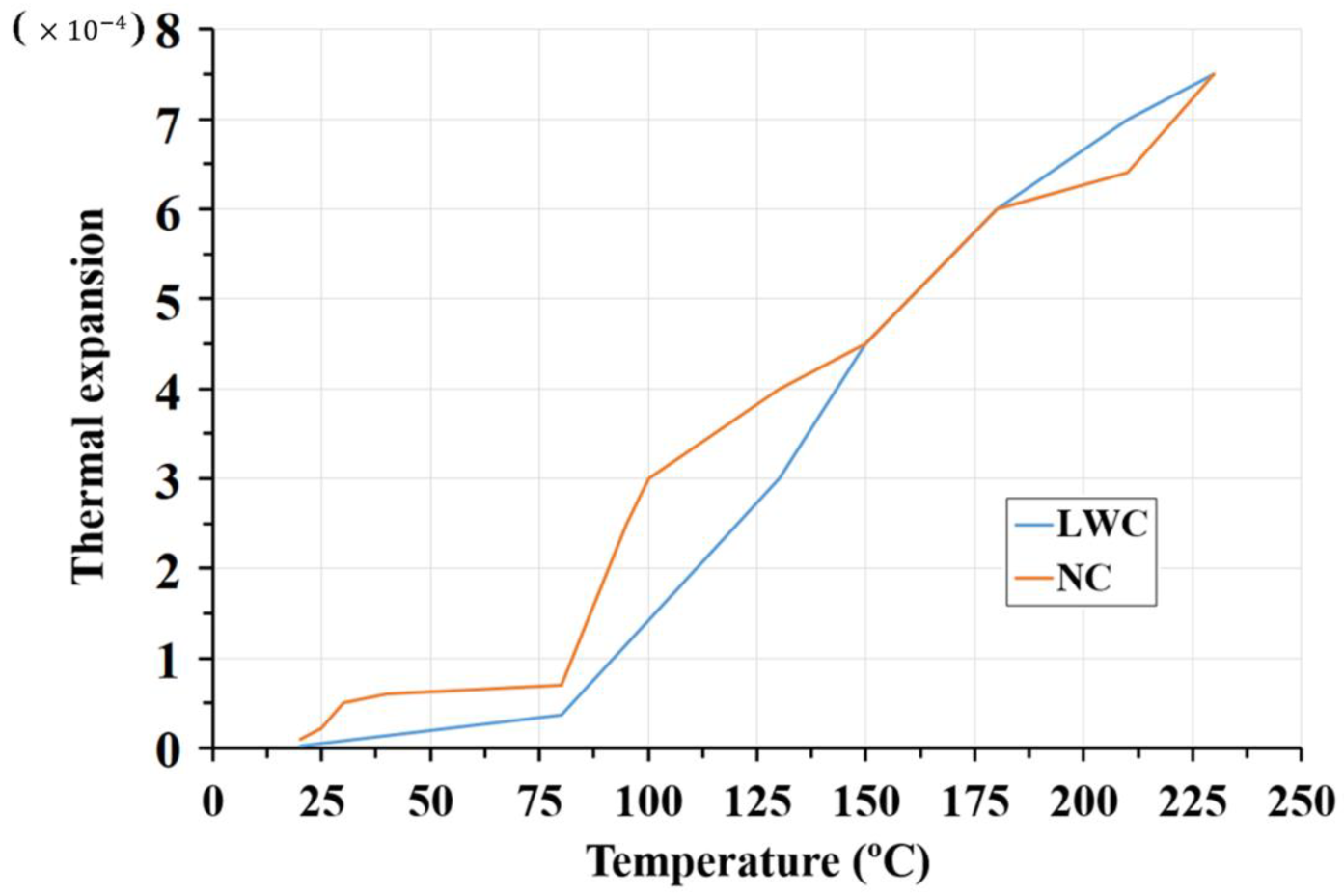
  • The validation of the numerical models is possible by defining thermal expansion. The correct definition of this parameter plays a fundamental role in ensuring that the coupled models follow the experimental evolution. The use of the values indicated in Eurocode 4 part 1–2 causes errors. These errors include a 30% discrepancy between experimental and numerical data, as well as the non-convergence of the model.
  • Differences between experimental and numerical temperatures at the thick part are attributed to the convection coefficient for the web of the steel decking. This value, taken from a previous work [42], does not take into account the vaporization phenomenon at the interface between steel decking and concrete. Future research works should be expanded to properly define this convection coefficient.
  • The use of different static structural analyses with a transient thermal analysis makes it possible to simulate the experimental structural behavior of composite slabs under fire conditions. The numerical model presented in this work is capable of accurately reproducing the structural behavior of the composite slabs after 500 s of testing, when the debonding has already happened. Until then, there are significant discrepancies between the experimental and numerical results, due to the complexity of the thermal and mechanical phenomena that occur in this phase.
  • In general, the proposed values of the thermal contact conductance coefficient provide good agreement with experimental results and satisfactorily simulated the debonding effect. However, the numerical results include a significant discrepancy between experimental and numerical data up to 500 s of normalized test time. Future works should study new coefficients as mentioned by Piloto et al. [24].

Author Contributions

Conceptualization, J.J.d.C.-D.; methodology, F.P.Á.-R.; validation, F.P.Á.-R.; investigation, F.P.Á.-R.; data curation, J.E.M.-M.; writing—original draft preparation, J.E.M.-M.; writing—review and editing, M.A.-M.; visualization, J.E.M.-M.; supervision, J.J.d.C.-D.; funding acquisition, J.J.d.C.-D. All authors have read and agreed to the published version of the manuscript.

Funding

This research was funded by Ministry of Science, Innovation and Universities of Spain, under project with funding number PGC2018-098459-B-I00, co-financed with EU FEDER funds. Furthermore, the authors also thank the regional funders through the Asturian Government and the Foundation for the Promotion in Asturias of Applied Scientific Research and Technology (FICYT), co-financed with EU FEDER funds under Research Project with funding number AYUD/2021/51328.

Institutional Review Board Statement

Not applicable.

Informed Consent Statement

Not applicable.

Acknowledgments

The authors of the research presented in this paper acknowledge Weber Saint-Gobain and Hiansa S.A. for the technical support and the materials contributed for the realization of the mixed slabs; we thank the company PRENOR S.L. for their collaboration in the manufacturing of the same. Finally, we thank Swanson Analysis Inc. for the use of the university research version of the ANSYS v 19 program in this paper.

Conflicts of Interest

The authors declare no conflict of interest.

Nomenclature

Acronyms
APDLANSYS parametric design language
CONTA174Surface to surface contact element (ANSYS software library)
ECCExpanded clay coarse
ECFExpanded clay fine
FEMFinite element method
IInsulation
LLoad-bearing capacity
LCALife-cycle assessment
LWCLightweight concrete
NISTNational Institute of Standards and Technology
NCNormal concrete
RIntegrity
SHELL1314-node shell heat transfer element (ANSYS software library)
SHELL2818-node shell element (ANSYS software library)
SOLID9020-node solid heat transfer element (ANSYS software library)
SOLID18620-node solid element (ANSYS software library)
TARGE170Surface to surface contact element (ANSYS software library)
XTransversal direction
ZLongitudinal direction
Symbols
Δ T Temperature rate
ε m f Deformation caused by the micro-cracks produced by the composition of the concrete
ε s Deformation caused by shrinkage
ε t Deformation measured experimentally
ε t e Effective thermal deformation
c e θ c Specific heat (kJ/kgK)
f c k Compression strength (MPa)
k 20 ° C Thermal conductivity of LWC at ambient temperature (W/mK)
k θ c Nonlinear thermal conductivity of LWC based on Eurocode 4 (W/mK)
k c c Thermal contact conductance coefficient (W/m2K)
L / 30 Load-bearing capacity criterion (mm)
Q c c Heat flux per unit area (W/m2)
Greek symbols
α Effective thermal expansion coefficient
θ c Temperature (°C)
θ c , C Temperature of the contact points on the contact surfaces (°C)
θ c , T Temperature of the contact points on the target surfaces (°C)

References

  1. Ahmed, I.M.; Tsavdaridis, K.D. Life cycle assessment (LCA) and cost (LCC) studies of lightweight composite flooring systems. J. Build. Eng. 2018, 20, 624–633. [Google Scholar] [CrossRef]
  2. Govindan, K.; Madan Shankar, K.; Kannan, D. Sustainable material selection for construction industry—A hybrid multi criteria decision making approach. Renew. Sustain. Energy Rev. 2016, 55, 1274–1288. [Google Scholar] [CrossRef]
  3. Sahlol, D.G.; Elbeltagi, E.; Elzoughiby, M.; Elrahman, M.A. Sustainable building materials assessment and selection using system dynamics. J. Build. Eng. 2020, 35, 101978. [Google Scholar] [CrossRef]
  4. Johnson, R.P.P. Composite Structures of Steel and Concrete, 3rd ed.; John Wiley and Sons Ltd.: Chicester, UK, 2004. [Google Scholar] [CrossRef]
  5. Abushanab, A.; Alnahhal, W.; Farraj, M. Structural performance and moment redistribution of basalt FRC continuous beams reinforced with basalt FRP bars. Eng. Struct. 2021, 240, 112390. [Google Scholar] [CrossRef]
  6. Purkiss, J.A. Fire Safety Engineering. In Design of Structures, 2nd ed.; Cambridge University Press: Cambridge, UK, 2007; Volume 53. [Google Scholar] [CrossRef]
  7. Kan, Y.C.; Chen, L.H.; Yen, T. Mechanical behavior of lightweight concrete steel deck. Constr. Build. Mater. 2013, 42, 78–86. [Google Scholar] [CrossRef]
  8. Arrayago, I.; Real, E.; Mirambell, E.; Marimon, F.; Ferrer, M. Experimental study on ferritic stainless steel trapezoidal decks for composite slabs in construction stage. Thin-Walled Struct. 2019, 134, 255–267. [Google Scholar] [CrossRef]
  9. Ahmed, I.M.; Tsavdaridis, K.D. Shear connection of prefabricated slabs with LWC–Part1: Experimental and analytical studies. J. Constr. Steel Res. 2020, 169, 106016. [Google Scholar] [CrossRef]
  10. Waldmann, D.; May, A.; Thapa, V.B. Influence of the sheet profile design on the composite action of slabs made of lightweight woodchip concrete. Constr. Build. Mater. 2017, 148, 887–899. [Google Scholar] [CrossRef]
  11. Martínez-Martínez, J.E.; Rabanal, F.P.Á.; Lázaro, M.; Alonso-Martínez, M.; Alvear, D.; del Coz-Díaz, J.J. Assessment of lightweight concrete thermal properties at elevated temperatures. Appl. Sci. 2021, 11, 10023. [Google Scholar] [CrossRef]
  12. del Coz-Díaz, J.J.; Martínez-Martínez, J.E.; Alonso-Martínez, M.; Rabanal, F.P.Á. Comparative study of LightWeight and Normal Concrete composite slabs behaviour under fire conditions. Eng. Struct. 2020, 207, 110196. [Google Scholar] [CrossRef]
  13. Jiang, J.; Main, J.A.; Weigand, J.M.; Sadek, F. Reduced-order modeling of composite floor slabs in fire. I: Heat-transfer analysis. J. Struct. Eng. 2020, 146, 04020080. [Google Scholar] [CrossRef]
  14. Lamont, S.; Usmani, A.S.S.; Drysdale, D.D.D. Heat transfer analysis of the composite slab in the Cardington frame fire tests. Fire Saf. J. 2001, 36, 815–839. [Google Scholar] [CrossRef]
  15. Pantousa, D.; Mistakidis, E. Advanced Modeling of Composite Slabs with Thin-Walled Steel Sheeting Submitted to Fire. Fire Technol. 2013, 49, 293–327. [Google Scholar] [CrossRef]
  16. Jiang, J.; Main, J.A.; Sadek, F.H.; Weigand, J.M. Numerical Modeling and Analysis of Heat Transfer in Composite Slabs with Profiled Steel Decking; National Institute of Standards and Technology: Gaithersburg, MD, USA, 2017. [Google Scholar] [CrossRef]
  17. UNE-EN 1994-1-2; Eurocode 4–Design of Composite Steel and Concrete Structures–Part 1–2: General Rules–Structural Fire Design. AENOR: Madrid, Spain, 2016.
  18. Piloto, P.A.G.; Prates, L.M.S.; Balsa, C.; Rigobello, R. Numerical simulation of the fire resistance of composite slabs with steel deck. Int. J. Eng. Technol. 2018, 7, 83. [Google Scholar] [CrossRef]
  19. Sharma, S.; Vaddamani, V.T.; Agarwal, A. Insulation effect of the concrete slab-steel deck interface in fire conditions and its influence on the structural fire behavior of composite floor systems. Fire Saf. J. 2019, 105, 79–91. [Google Scholar] [CrossRef]
  20. Nguyen, M.P.; Nguyen, T.T.; Tan, K.H. Temperature profile and resistance of flat decking composite slabs in- and post-fire. Fire Saf. J. 2018, 98, 109–119. [Google Scholar] [CrossRef]
  21. Li, G.-Q.Q.; Zhang, N.; Jiang, J. Experimental investigation on thermal and mechanical behaviour of composite floors exposed to standard fire. Fire Saf. J. 2017, 89, 63–76. [Google Scholar] [CrossRef]
  22. Bolina, F.; Tutikian, B.; Rodrigues, J.P.C. Thermal analysis of steel decking concrete slabs in case of fire. Fire Saf. J. 2021, 121, 103295. [Google Scholar] [CrossRef]
  23. Piloto, P.A.; Balsa, C.; Santos, L.M.; Kimura, É.F. Effect of the load level on the resistance of composite slabs with steel decking under fire conditions. J. Fire Sci. 2020, 38, 212–231. [Google Scholar] [CrossRef]
  24. Filho, M.M.A.; Piloto, P.A.G.; Balsa, C. Thermal Behaviour of Rebars and Steel Deck Components of Composite Slabs under Natural Fire. J. Compos. Sci. 2022, 6, 232. [Google Scholar] [CrossRef]
  25. UNE-EN 13381-5; Test Methods for Determining the Contribution to the Fire Resistance of Structural Members–Part 5: Applied Protection to Concrete/Profiled Sheet Steel Composite Member. AENOR: Madrid, Spain, 2016.
  26. UNE-EN 1363-1; Fire Resistance Tests–Part 1: General Requirements. AENOR: Madrid, Spain, 2021.
  27. UNE-EN ISO 6892-1; Metallic Materials–Tensile Testing–Part 1: Method of Test at Room Temperature (ISO 6892-1:2019). AENOR: Madrid, Spain, 2020.
  28. UNE-EN 12390-13; Testing Hardened Concrete–Part 13: Determination of Secant Modulus of Elasticity in Compression. AENOR: Madrid, Spain, 2014.
  29. UNE 83507; Concrete with Fibres. Testing in Compression. AENOR: Madrid, Spain, 2004.
  30. ISO 834-1; Fire-Resistance Tests-Elements of Building Construction–Part 1: General Requirements. International Organization for Standardization: Geneva, Switzerland, 1999.
  31. Balsa, C.; Silveira, M.; Mange, V.; Piloto, P.A.G. Modelling the Thermal Effects on Composite Slabs Under Fire Conditions. Computation 2022, 10, 94. [Google Scholar] [CrossRef]
  32. Thompson, M.; Thompson, J. ANSYS Mechanical APDL for Finite Element Analysis; Butterworth-Heinemann: Oxford, UK, 2017. [Google Scholar]
  33. Lim, L.; Wade, C. Experimental Fire Tests of Two-Way Concrete Slabs; University of Canterbury School of Engineering: Christchurch, New Zealand, 2002. [Google Scholar]
  34. Ghojel, J. Experimental and analytical technique for estimating interface thermal conductance in composite structural elements under simulated fire conditions. Exp. Therm. Fluid Sci. 2004, 28, 347–354. [Google Scholar] [CrossRef]
  35. Espinos, A.; Romero, M.L.; Hospitaler, A. Advanced model for predicting the fire response of concrete filled tubular columns. J. Constr. Steel Res. 2010, 66, 1030–1046. [Google Scholar] [CrossRef]
  36. Tao, Z.; Ghannam, M. Heat transfer in concrete-filled carbon and stainless steel tubes exposed to fire. Fire Saf. J. 2013, 61, 1–11. [Google Scholar] [CrossRef]
  37. Rokilan, M.; Mahendran, M. Elevated temperature mechanical properties of cold-rolled steel sheets and cold-formed steel sections. J. Constr. Steel Res. 2019, 167, 105851. [Google Scholar] [CrossRef]
  38. Alain, M.; Pierre, P. Modelling of Concrete Behaviour at High Temperature; Springer International Publishing: Cham, Switzerland, 2019; Volume 30. [Google Scholar] [CrossRef]
  39. Kodur, V.; Dwaikat, M.; Fike, R. High-Temperature Properties of Steel for Fire Resistance Modeling of Structures. J. Mater. Civ. Eng. 2010, 22, 423–434. [Google Scholar] [CrossRef]
  40. Meseguer, Á.G.; Cabré, F.M.; Portero, J.C.A. Jiménez Montoya Hormigón Armado, 15th ed.; GUSTAVO GILI: Barcelona, Spain, 2010. [Google Scholar]
  41. UNE-EN 1991-1-2; Eurocode 1: Actions on Structures–Part 1–2: General Actions–Actions on Structures Exposed to Fire. AENOR: Madrid, Spain, 2019.
  42. Jiang, J.; Main, J.A.; Weigand, J.M.; Sadek, F.H. Thermal performance of composite slabs with profiled steel decking exposed to fire effects. Fire Saf. J. 2018, 95, 25–41. [Google Scholar] [CrossRef]
Figure 1. Steel decking profile (dimensions in mm): (a) Trapezoidal steel decking in the composite slab. (b) Composite slab cross section.
Applsci 12 09306 g001
Figure 2. Details of the fire tests: (a) Top view of the slab and arrangement of thermocouples (units: mm). (b) Cross section of the slab (units: mm). (c) Test setup.
Applsci 12 09306 g002
Figure 3. Average temperature at zones A and B (non-exposed side of the slab).
Applsci 12 09306 g003
Figure 4. Average temperature at zones C and D (steel decking).
Applsci 12 09306 g004
Figure 5. Average temperature within concrete at zones E and F (cross section of the slab).
Applsci 12 09306 g005
Figure 6. Fire test phenomena of composite slabs: (a) Debonding of the steel decking. (b) Water at the top of the slab. (c) Crack pattern (unit: mm).
Applsci 12 09306 g006
Figure 7. Comparative mechanical behavior of composite slabs studied.
Applsci 12 09306 g007
Figure 8. Geometry of the FEM model.
Applsci 12 09306 g008
Figure 9. Thermal properties of LWC and NC: (a) thermal conductivity, and (b) specific heat.
Applsci 12 09306 g009
Figure 10. Thermal expansion values of LWC and NC as a function of temperature.
Applsci 12 09306 g010
Figure 11. Boundary conditions applied to the model: (a) Symmetry, support, and load conditions; (b) Temperature conditions.
Applsci 12 09306 g011
Figure 12. FEM temperature inside concrete at 1800 s: (a) LWC-1; (b) LWC-2; (c) LWC-3; (d) NC.
Applsci 12 09306 g012aApplsci 12 09306 g012b
Figure 13. FEM vertical displacement (mm) at 1800 s: (a) LWC-1; (b) LWC-2; (c) LWC-3; (d) NC.
Applsci 12 09306 g013
Figure 14. Comparison between experimental (solid lines) and FEM (dashed lines) temperatures in the contact zone between the steel decking and the concrete: zones C and D.
Applsci 12 09306 g014
Figure 15. Comparison of experimental (solid lines) and FEM (dashed lines) temperatures at zones E and F: (a) LWC-1 and LWC-2; (b) LWC-3 and NC.
Applsci 12 09306 g015
Figure 16. Comparison of experimental (solid lines) and FEM (dashed lines) temperatures at zones A and B: (a) LWC-1 and LWC-2; (b) LWC-3 and NC.
Applsci 12 09306 g016
Figure 17. Comparison of FEM and experimental tests: (a) LWC-1; (b) LWC-2; (c) LWC-3; (d) NC.
Applsci 12 09306 g017
Table 1. Properties of steel decking.
Elastic Modulus (MPa)Young’s Modulus (GPa)Poisson Coefficient
Average value2712080.31
Standard Deviation3.5120
Table 2. Mixing proportions of lightweight concretes in mass fractions.
Mixing CompositionsConstituents
ECF (%)ECC (%)Siliceous Aggregate 0/2 (%)Cement 42.5R (%)Water (%)
LWC-15.856.0540.4232.1415.54
LWC-25.894.1144.6830.5514.77
LWC-33.914.5044.4431.7915.36
Table 3. Material properties of concrete.
TypeBulk Density
(kg/m3)
Compression Strength
(fck, MPa)
Strength ClassYoung’s Modulus
(GPa)
Thermal Conductivity (k20°C, W/m·K)Specific Heat
(J/kgK)
LWC-1174025.60LC 25/282071.65950
LWC-2181928.59LC 25/282161.73840
LWC-3190630.22LC 30/332721.51850
NC235036.97C 30/374572.52900
Table 4. Relationship between ambient temperature and kCC values.
Temperature (°C)kCC (W/m2 K)
2010
604.510
60715
673.715
675.220
827.120
Table 5. Relative error between numerical and experimental results.
Time (s)LWC-1LWC-2LWC-3NC
1004.2011.763.3962.48
30024.9129.8927.8952.78
50012.0412.6014.4433.02
7004.103.203.6312.74
9005.581.883.27.9.94
11008.153.982.707.10
13008.863.243.672.05
15003.923.154.112.99
170017.936.240.060.35
Publisher’s Note: MDPI stays neutral with regard to jurisdictional claims in published maps and institutional affiliations.

