Article

Automatic Cause–Effect Graph Tool with Informal Korean Requirement Specifications

Software Engineering Laboratory, Department of Software and Communication Engineering, Hongik University, Sejong 30016, Korea
*
Author to whom correspondence should be addressed.
Appl. Sci. 2022, 12(18), 9310; https://doi.org/10.3390/app12189310
Submission received: 1 August 2022 / Revised: 13 September 2022 / Accepted: 13 September 2022 / Published: 16 September 2022

Abstract

:
In requirement engineering, it is a very important issue to generate test cases with natural language automatically. However, no test case tools deal with informal Korean requirement specifications. In the Korean military software system and airspace industrial area, it is strongly suggested to automatically make just 30% of all possible test cases with requirements. Unlike the previous approaches, we adapted Gary E. Mogyorodi’s cause-effect graphing approach and the model-driven architecture (MDA) approach for automatic test case generation with natural language. In order to generate test cases with informal Korean requirement specifications, we propose an automatic cause–effect tool as an intermediate model for (1) simplifying complicated requirements; (2) modeling the C3Tree (that is, condition and result); (3) identifying incomplete requirements; (4) constructing causes, effects, and relationships; and (5) integrating with two units (that is, similar causes or effects) to remove redundant requirements. We evaluated the accuracy of two generated cause–effect graphs in two ways. With our approach, we can also remove requirement redundancy.

1. Introduction

In the current requirement engineering area, it is very difficult to deal with natural language requirements. However, stakeholders easily understand requirements that are written in natural language. This natural language requirement has some problems, such as inconsistency, inaccuracy, and ambiguity. In order to deal with this problem, some researchers use formal methods such as Z specification and mathematic logic to convert natural language requirements. Therefore, we focused on natural language requirements, especially Korean requirements.
In software organizations, tests are performed using white box and black box approaches, using various test tools to develop high-quality software and considering test time and costs [1].
Many researchers researched test case generations via Z specification, UML models (use case, sequence, object, state, and activity diagram), or code. Few researchers researched test case generation with natural language. In requirement engineering, until now, no one has worked on informal Korean requirements because it is very difficult to analyze Korean sentences semantically. In order to solve these difficulties, we adapted requirement engineering with a natural language approach. In the near future, we will propose an automatic test case generation method from informal Korean requirements.
As an intimate model for generating test cases, we proposed a cause–effect graph in Korean language requirements [2,3] without requirement redundancy.
Therefore, we considered how to deal with removing requirement redundancy on cause–effect generation as the intimate model for test case generation.
In order to solve requirement redundancy, we adapted requirement engineering with Jaccard’s similarity mechanism to identify the redundancy of requirement specifications.
In this paper, we proposed our cause–effect generation method in informal Korean requirements specifications with the tool environment for the cause–effect graph generation method, which improves our automatic approach as follows: (1) simplify informal Korean requirements, (2) construct a C3Tree model for the simplification process of Korean sentences [3], (3) identify the similarity between nodes of C3Tree model, and (4) generate cause–effect graph with C3Tree models. Additionally, for accuracy, we evaluated the manual and automatic cause–effect graph generations with two examples.
This paper is structured as follows: Section 2 refers to related studies. Section 3 explores the automatic generation of the cause–effect graph from informal Korean requirements. Section 4 discusses the evaluation of the Korean requirement analyzer for the cause–effect graph (called KRA-CE). Finally, the conclusion is presented.

2. Related Studies

In requirement-based testing, most researchers considered a formal language, UML, or natural language for requirement specification. However, we have difficulty dealing with natural language-based requirements. Farooq [4] also mentioned natural language requirements with ambiguity, lack of consistency, inaccuracy, and incomplete information. Alder [5] focused on a semi-formal mechanism for specifying the English language description of the function. Myers suggests the cause–effect graph in specifying the functional behavior of a program and formalization based on mathematical logic. We found it unwise to use this cause–effect graph to represent the large English language descriptions.
The existing tools should manually draw the cause–effect graph without analyzing requirements. It provides various functions for entering and managing detailed information. We compared current representative cause–effect graph tools as follows:
Hongik MDA-based embedded software component development methodology (HiMEM) [6] is a tool that supports the generation of test cases from use case descriptions. We suggest the process of generating test cases from the use case specifications without requirement specifications, which generates a cause–effect graph from each use case diagram/sequence diagram. This tool also uses various UML diagrams. BenderRBT [7] supports manually drawing the cause–effect graph, which automatically generates test cases via decision tables. Without requirement specifications, this tool needs to be manually input. That is, this tool does not analyze its requirements. Berk Bekiroglu’s cause–effect graph testing tool [8] also automatically generates a test case via a decision table with a manual cause–effect graph. It provides input and management functions for node logic, type, test process observation, and true/false state description. This tool does not analyze its requirements.
Gary E. Mogyorodi noted that 100% coverage could be satisfied with the minimum number of test cases [9] if a test case is generated with his cause–effect graph at the top of Figure 1. In the middle of Figure 1, our previous approach generates a cause–effect graph from each use case and sequence diagram [10,11], which does not use requirement specifications. At the bottom of Figure 1, we mentioned how to generate a cause–effect graph with natural language. This method generates a cause–effect graph via a C3Tree model from informal Korean requirements [3].
Our proposed Korean requirement analyzer for cause–effect graph (KRA-CE) automatically generates cause–effect graph from informal requirements specifications. By providing web-based UIs, we will potentially work with other web-based tools. Table 1 shows the difference between KRA-CE and the existing tools. O is Yes. X is no.
Most previous researchers do not work automatically to generate test cases from requirement specifications written in diverse natural languages. Our research focuses on automatically generating test cases with Korean requirement specifications. IBM researchers focus on recognizing and splitting conditional sentences for the automation of business process management, which identifies the causes and effects of English sentences based on a deep learning approach [12]. However, they have difficulty analyzing complex sentences.

3. Automatic Generation for Cause–Effect Graph from Informal Korean Requirements

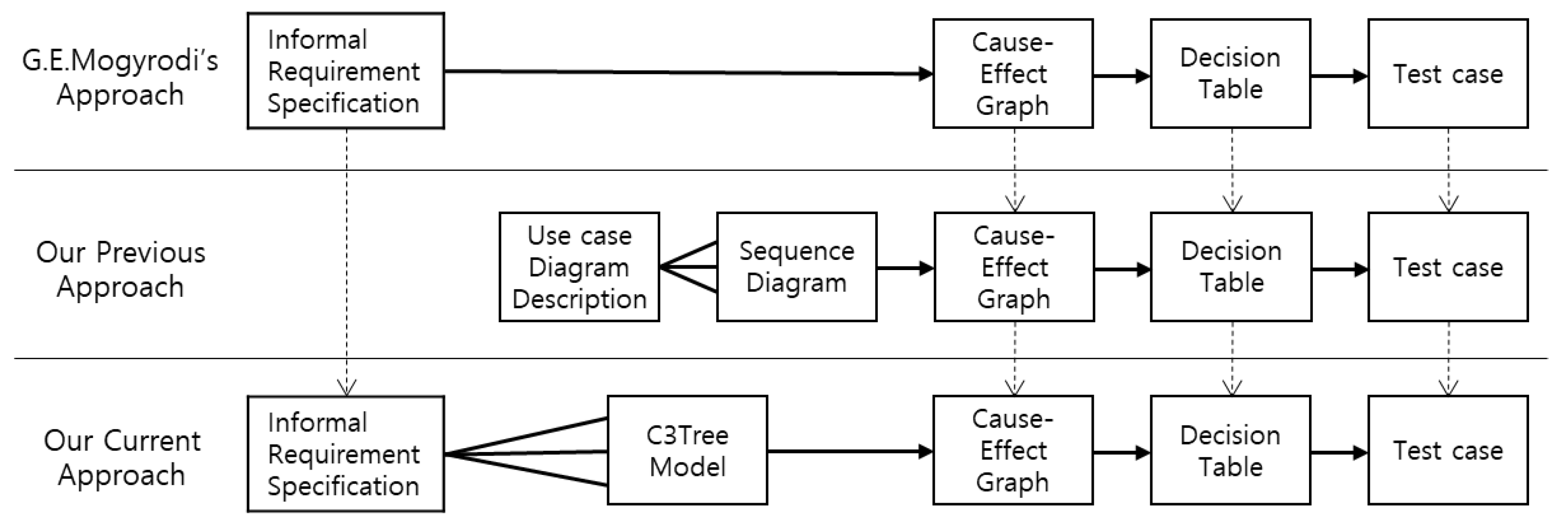
3.1. Automatic Generation Process for Cause–Effect Graph from Korean Requirements on Our Informal Korean-Based Requirement Analyzer

Figure 2 shows the cause–effect graph generation process using informal Korean requirements. The detailed process is as follows.
  • Step 0. Input Informal Korean Requirements
In order to explain this, we used a simple sample of Korean language requirements in Table 2.
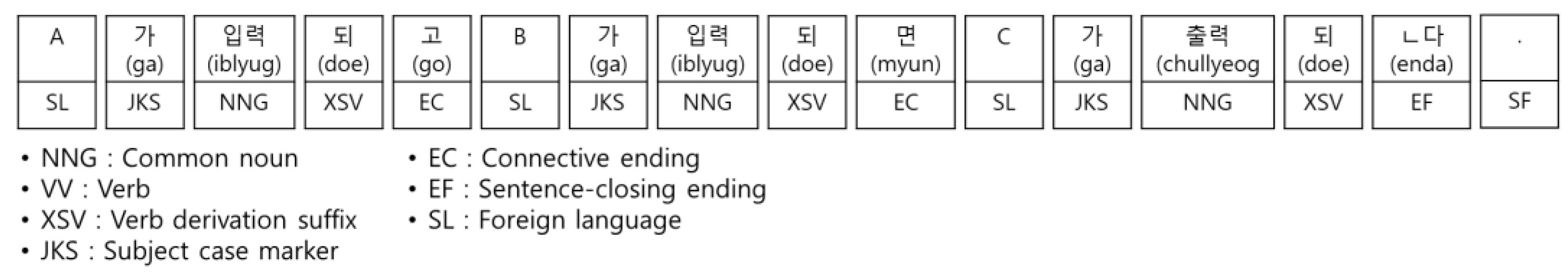
  • Step 1. Identify Morpheme
In order to identify morphemes in requirement sentences, we used the open-source morpheme analyzer MeCab-ko [13]. This analyzer slices a requirement sentence into small units, that is, morphemes.
Figure 3 shows the identified morphemes of the sentence in Table 2.
  • Step 2. Simplify Complex Requirement Sentences
In this step, we identified “Cause” and “Effect” nodes and also constructed “Identity”, “NOT”, “AND”, and “OR” relationships between “Cause” and “Effect” nodes in natural Korean sentences. Then, it automatically generates a cause–effect graph that contains the “Cause” node in the condition clause and the “Effect” node in the result clause of a natural language sentence. The “AND” or “OR” relationship exists between a conjunction clause and the following clause nested from each “Cause” and “Effect” node. It can also contain the “NOT” relationship in the condition and result clauses.
In order to analyze the morpheme in a sentence, we used a morpheme analyzer to identify the “Condition”, “Result”, “Conjunction”, and “Following” types of the clauses in the sentence included with the analyzed morphemes.
In order to explain four cases for identifying the inner structure of a requirement sentence, we use other samples of requirements as follows:
  • Identify the positive and negative condition relationships;
When the tool identifies the sentence’s conditional and the result clauses, the clauses are classified as positive or negative. For example, the root node contains a complex sentence as the original requirement sentence. A parent node represents a sliced sentence from the original sentence. The terminal nodes contain the simple sentences in the red rectangle boxes. This original sentence contains a positive condition relationship. Figure 4 shows the positive conditional relationship of the sentence.
  • Identify the AND or the OR conjunction relationships;
When the tool identifies the conjunction clauses and the following clauses in the sentence, the conjunction clauses are classified as AND type or OR type. This original sentence contains the AND relationship. This shows to simplify a complex sentence with the AND relationship. Figure 5 shows the AND conjunction relationship of the sentence.
  • Normalize corpus;
The tool changes passive sentences into active sentences and restores the subject from the sentence. Figure 6 shows an example of changing a passive sentence into an active sentence.
  • Identify the order of different clauses in a complex requirement sentence.
The condition cause and the conjunction cause are not identified in order. Sometimes we find two causes: (1) the condition cause may be placed first, or (2) sometimes the conjunction cause may be identified first. We emulated some patterns for the clause identification sequence in Table 3. For example, if the sentences in the fourth pattern are defined in the order of condition cause -> conjunction cause, then we identified the conjunction cause and the condition causes in this order.
An example of the first pattern in Table 3 is shown in the equation below. If two CFs are identified, the two clauses have AND|OR relations.
This is the first pattern example:
n = 1 2 ( C F n ) = C F 1 + C F 2 = C F 1   { AND | OR | NOT }   C F 2
With KRA-CE, we sliced a complex sentence into morphemes and identified the connective ending (EC) in morphemes. In Korean, the EC is a morpheme that separates clauses. The sentence is sliced into three clauses, C1, C2, and C3. Since this sentence corresponds to the third pattern in Table 3, and it is identified in the order of C1->C2->C3. Figure 7 shows the identification of three simple clauses (the order of C1->C2->C3) in a complex sentence.
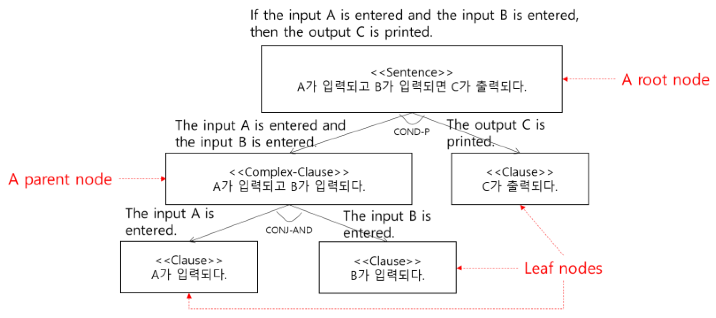
  • Step 3. Generate Condition/Conjunction/Clause Tree (C3Tree) Model
The KRA-CE tool constructs the C3Tree model as an intermediate model between a complex sentence and simplified sentences, that is, the process of slicing complex sentences into simplified sentences similar to a tree style. A <<Sentence>> node contains a complex original sentence. The <<Complex-Clause>> node includes several <<Cause>> nodes, which contain simplified sentences.
A root node represents an original requirement sentence. The parent nodes are sliced with the root node, and they have child nodes. A child node is a sliced sentence, and a single parent node can have multiple child nodes. The left child node of the condition-positive relationship (COND-P) is the cause sentence, the right child node of COND-P is the result sentence, the left node of the condition-negative relationship (COND-N) is the cause sentence, and the node to the right of COND-N is the negative result sentence. If all child nodes of the Conjunction-AND Relationship (CONJ-AND) are valid, then the parent node is valid. If any of the child nodes of the Conjunction-OR Relationship (CONJ-OR) are true, then the parent node is valid [3].
The top node is an original sentence as the root node. The bottom nodes are the simplified sentences as the leaf or terminal nodes. In order to explain it well, we added English comments on the node. Figure 8 shows a C3Tree model for slicing a complex sentence into simplified sentences in a tree style.
  • Step 4. Unify with Two Similar Nodes in C3Tree Models
Our previous method [3] generated the cause–effect graph via the C3Tree model from the Korean requirements. The problem does not consider redundant requirements, which means keeping redundant test cases. In order to solve this problem, we identified the similarities of nodes in the C3Tree model with the Jaccard mechanism [14] and then unified two similar nodes into one node.
In Step 4 of Figure 2, we mentioned the detailed process as follows: (1) identify the leaf nodes (that is, simple sentences) in the C3Tree model of a requirement sentence; (2) define all possible pairs of leaf nodes, that is, pair combinations of all identified nodes; (3) measure the Jaccard similarity of all possible pairs (the J means Jaccard similarity); (4) measure the pair set with theta roles if the similarity is greater than or equal to 0.8 (the T means theta role); (5) unify similar nodes into one if all theta roles between nodes are the same. Therefore, we removed the redundant nodes. As a result, all C3Tree models can be converted into one unified C3Tree model.
Figure 9 is a simple example of Step 4 in Figure 2. We demonstrated generating two C3Tree models from two Korean requirements and then compared the Jaccard similarity and theta role of leaf nodes in two C3Tree models. A detailed description is given below.
· Similarity Measurement with Jaccard mechanisms
We adapted requirement engineering with the similarity mechanism to identify the redundancy of requirement specifications.
For our adaption, we may assign that A in the original formula may be a set of morphemes within an informal Korean requirement sentence, R1, and B may also be a set of morphemes within another requirement sentence, R2.
This is the original Jaccard similarity formula:
J ( A , B ) = A   B A   B = A   B | A | + | B | | A   B |
In requirement engineering, we measured the similarity between two pair sets, that is, the sets of the morphemes of the <<Clause>> nodes in the C3Tree models of requirement sentences R1 and R2. The similarity measurement process is as follows: (1) identify the morphemes of all <<Clause>> nodes and (2) compare all <<Clause>> node morphemes. In this case, the case marker morpheme (only Korean morpheme) was removed because it does not have any meaning in our approach.
In the Jaccard Similarity part of Figure 9, we identified similar nodes in two C3Tree models. The <<Clause>> nodes in the red boxes have three different morphemes, and two morphemes are the same. However, the three morphemes have no direct meaning. For example, the JKS and JKO are case marker morphemes. In Korean, the subject and object are not determined by the position in the sentence. The subject is a noun modified by JKS.KS. A noun modified by JKO is an object. The JKS and JKO determine the role of nouns and have no direct meaning. The XSV determines the active/manual role of the verb, and the EF means the end of a sentence. As a result, the morphemes with no direct meaning are excluded from the measurement item.
Our tool calculates this score of similarity. If this score is more than 0.8, we decide to have two causes/effects similar, then unify them.
Figure 10 shows the union, intersection, and similarity of Figure 9.
· Theta-role comparison
Even if the score of the Jaccard similarity is high, the meaning between sentences may be different. In order to solve this problem, we identified and combined clauses with overlapping meanings using the theta-role [15]. A theta-role refers to a participant’s role (or semantic argument) in a semantic structure related to a predicate. The predicate may be a verb, an adjective, or a noun. Table 4 shows the list of theta-roles [15]. It is a part of the theta-roles in Sejong’s Electronic Dictionary.
Analyze theta-role in Electronics and Telecommunications Research Institute(ETRI)’s Exobrain library [15]. The theta role part in Figure 9 compares the theta role of leaf nodes in the C3Tree model with a Jaccard similarity of 0.8 or higher. When comparing the pair combination of two leaf nodes, two nodes have the same theta role.
  • Step 5. Transform C3Tree Model to Cause–Effect Graph
The C3Tree model is transformed into a cause–effect graph. The C3Tree model’s terminal nodes are transformed into the cause–effect graph’s nodes. The link of the C3Tree model is transformed into the relation of the cause–effect graph.
Figure 11 shows two Korean requirements to generate a cause–effect graph. The C3Tree model has six leaf nodes and two similar nodes. Therefore we unified two similar leaf nodes into one node. As a result, the five nodes of cause–effect graph are generated.

3.2. A Cae Study with Our KRA-CE Analyzer

Figure 12 shows the implementation environment of KRA-CE. We used the Ubuntu Operation system and Mecab-ko or KoNLP as Korean morpheme analyzers. Chart.js is a web-based graphing library, Apache PHP is a web server, Python is a development environment for executing a morpheme analyzer, and JDK is a development environment for the execution of the toolchain. The KRA-CE is developed using Java.
The executing procedure of our KRA-CE tool is as follows:
Identification of morpheme: identify morphemes in sentences;
Simplification of complex requirements: (1) slice the requirement sentence into clause units and (2) identify a conditional clause, a result clause, and a conjunction clause with AND role/OR role [16,17]; (3) convert the sliced clauses into simplified sentences; (4) convert a passive sentence into an active sentence [18,19];
Generation of C3Tree model: simplify complex sentences;
Unification of similar nodes in the C3Tree model: (1) identify similar nodes among terminal nodes of all C3Tree models and (2) combine similar nodes into one;
Transformation C3Tree model to cause–effect graph: (1) transform the <<Clause>> of the C3Tree model into a node of the cause–effect graph and (2) transform the link of the C3Tree model into the relationship of the cause–effect graph;
In the near future, we will work on the KRA-Test Case Generation as follows: (1) transform the cause–effect graph to the decision table; (2) transform the decision table to the test case; (3) transform the test case to the test script.
Figure 13 shows input requirements on the UI menu. The black box at the top of Figure 13 is the program’s menu. The Save button saves the entered requirement sentence. The Reset button restores the modified requirements to the original requirements.
Figure 14 shows the generated C3Tree model as the output of ①, ②, ③, and ④ in Figure 12. The model is saved as a file consisting of XMI code. The saved XMI code is drawn on the screen through Chart.js. The model’s XMI code is output in the middle of the screen in Figure 14. If the XMI code is changed, the structure of the model is changed.
Figure 15 is the generated cause–effect graph as the output of ⑤ in Figure 12. It is stored as XMI code similar to the C3Tree model. If the XMI code is changed, the structure of the model is changed.

4. Discussion

In order to prove the correctness of our automatic cause–effect generation, we evaluated two cases with five requirements. One manually makes the cause–effect graph. Another automatically generates the cause–effect graph with the KRA-CE. Table 5 is a list of example requirements.
At the top of Figure 16, we show the comparison of the cause–effect graph drawn by humans and KRA-CE. Eight nodes are identified and connected. Two flows are expressed and include the AND. On the right of Figure 16, we show cause–effect graph drawn by KRA-CE. This has the same results as the left graph.
In other cases, we use the sample requirement and cause–effect diagram in Myers’s paper [2]. Table 6 is an example of the requirements mentioned by Glenford J. Myers [2]. On the left side of Figure 17, we show a cause–effect graph of requirements of the requirements written by Myers in Table 6. On the right side of Figure 17, we show the cause–effect graph of KRA-CE automatically generated from Myers’s requirements in Table 6.
In Figure 17, the two cause–effect graphs have similar structures. In the case of Myers, the cause was defined as A1, A2, and A3, and the effect was defined as M1, M2, and M3. Additionally, an E intermediate node was added to connect A1 and A2 in an OR relationship. In the case of KRA-CE, A1 and A2 were expressed as one node. The rest of the nodes have the same structure.

5. Conclusions

In the current requirement engineering area, it is very difficult to deal with natural language requirements. However, stakeholders easily understand requirements that are written in natural language. This natural language requirement has diverse problems, such as inconsistency, inaccuracy, and ambiguity. In order to solve this problem, some researchers use formal methods such as Z specification and mathematic logic to convert natural language requirements. However, few researchers deal with natural language requirements, especially English language descriptions. We focused on Korean language-based requirements. In order to solve requirement redundancy, we adapted requirement engineering with Jaccard’s similarity mechanism to identify the redundancy of requirement specifications.
Therefore, we proposed an automatic cause–effect tool for (1) simplifying complicated requirements; (2) modeling the C3Tree model (that is, condition and result); (3) identifying wrong requirements; and (4) constructing causes, effects, and relationships. In addition, there are two functions that integrate two units (that is, similar causes or effects) into one to identify similar requirements and extract incomplete requirements for guiding refined requirements. Furthermore, we designed the tool environment for implementing the given method, then evaluated the accuracy of the generated cause–effect diagram with requirements. We are extending to automatically generate test cases via decision tables based on this cause–effect diagram.
In the near future, we will study (1) sentence analysis with AI-based learning, (2) improvement of sentence similarity analysis, and (3) adverbial phrase processing.

Author Contributions

W.S.J. and R.Y.C.K. designed the present study and drafted the manuscript; W.S.J. developed the present study; W.S.J. and R.Y.C.K. performed the validation and verification of the cause–effect graph generation process, reviewed the literature, and critically revised the manuscript. All authors have read and agreed to the published version of the manuscript.

Funding

The research was supported by Basic Science Research Program through the National Research Foundation of Korea (NRF), funded by the Ministry of Education (No. 2021R1I1A3050407, No. 2021R1I1A1A01044060) and the BK21 FOUR (Fostering Outstanding Universities for Research) funded by the Ministry of Education (MOE, Korea) (No. F21YY8102068).

Conflicts of Interest

The authors have no conflict of interest.

References

  1. Kwon, O.S.; Hong, S.N. Effective Iterative Testing based on Log. In Proceedings of the Korea Society of Management Information Systems Fall Conference, Seoul, Korea, 6 November 2009; pp. 685–690. [Google Scholar]
  2. Myers, G.L. The Art of Software Testing; Wiley-Interscience: London, UK, 1979. [Google Scholar]
  3. Jang, W.S.; Kim, R.Y.C. Automatic Generation Mechanism of Cause-Effect Graph with Informal Requirement Specification based on Korean Language. Appl. Sci. 2021, 11, 11775. [Google Scholar] [CrossRef]
  4. Farooq, M.S.; Tahreem, T. Requirement-Based Automated Test Case Generation: Systematic Literature Review. VFAST Trans. Softw. Eng. 2021, 9, 133–142. [Google Scholar]
  5. Adler, M.; Gray, M.A. A Formalization of Myers Cause-Effect Graphs for Unit Testing. ACM SIGSOFT Softw. Eng. Notes 1983, 8, 24–33. [Google Scholar] [CrossRef]
  6. Kim, W.Y.; Kim, R.Y.C. A Study on Modeling Heterogeneous Embedded S/W Components based on Model Driven Architecture with Extended xUML. Korea Inf. Process. Soc. Trans. Part D 2007, 14, 83–88. [Google Scholar]
  7. BenderRBT, BenderRBT. Available online: https://www.benderrbt.com (accessed on 5 April 2022).
  8. Bekiroglu, B. A cause-effect graph software testing tool. Eur. J. Comput. Sci. Inf. Technol. 2017, 5, 11–24. [Google Scholar]
  9. Mogyorodi, G.E. Requirements-Based Testing-Cause-Effect Graphing. Softw. Test. Serv. 2005, 1–12. [Google Scholar]
  10. Son, H.S.; Kim, R.Y.C.; Park, Y.B. Test Case Generation from Cause-Effect Graph based on Model Transformation. In Proceedings of the International Conference on Information Science & Applications (ICISA), Seoul, Korea, 6–9 May 2014; pp. 1–4. [Google Scholar]
  11. Woo, S.J.; Son, H.S.; Kim, W.Y.; Kim, J.S.; Kim, R.Y.C. A Study Testcase Extraction based M&S for Pre-Testing. In Proceedings of the Korea Conference on Software Engineering, Jeju, Korea, 22–25 November 2012; Volume 14, pp. 181–183. [Google Scholar]
  12. Vo, N.P.A.; Manotas, I.; Popescu, O.; Cerniauskas, A.; Sheinin, V. Recognizing and Splitting Conditional Sentences for Automation of Business Processes Management. In Proceedings of the International Conference on Recent Advances in Natural Language Processing (RANLP 2021), Varna, Bulgaria, 9–10 September 2021; pp. 1490–1497. [Google Scholar]
  13. Mecab-Ko-Dic. Available online: https://bitbucket.org/eunjeon/mecab-ko-dic (accessed on 5 April 2022).
  14. Agresti, A. Categorical Data Analysis; John Wiley and Sons: Hoboken, NJ, USA, 1990. [Google Scholar]
  15. Lim, S.J.; Kwon, M.J.; Kim, J.S.; Kim, H.K. Korean Proposition Bank Guidelines for ExoBrain. In Proceedings of the 27th Annual Conference on Human & Cognitive Language Technology, Atlanta, GA, USA, 28–31 May 2015; pp. 250–254. [Google Scholar]
  16. Ha, J.M. A Contrastive Study on Korean Conditional Connective Ending and Chinese Conditional Conjunction Expression; Kyunghee University: Seoul, Korea, 2007. [Google Scholar]
  17. Kim, K.S. A Comparative study on conjoined sentence between modern Mongolian and Korean. Korean Assoc. Mong. Stud. 2009, 151–186. [Google Scholar]
  18. Cho, J.M.; Cho, Y.H.; Kim, G.C. A Corpus Formalization for Extracting the Syntactic Relations. In Proceedings of the 8th Annual Conference on Human & Cognitive Language Technology, Daejeon, Korea, 11–12 October 1996; pp. 207–215. [Google Scholar]
  19. Cho, J.M.; Kim, G.C. A Corpus Formalization for Extracting the Syntactic Relations. Korean Soc. Cogn. Sci. 1996, 7, 39–56. [Google Scholar]
Figure 1. Automatic cause–effect design mechanism for test cases.
Applsci 12 09310 g001
Figure 2. The cause–effect graph generation process based on informal Korean requirement specifications.
Applsci 12 09310 g002
Figure 3. Analyzed morphemes of the sentence.
Applsci 12 09310 g003
Figure 4. Positive condition relationship.
Applsci 12 09310 g004
Figure 5. AND conjunction relationship.
Applsci 12 09310 g005
Figure 6. Corpus normalization.
Applsci 12 09310 g006
Figure 7. Three clauses’ Identification (this order of C1->C2->C3) in the sentence.
Applsci 12 09310 g007
Figure 8. C3Tree model for representing sample sentences.
Applsci 12 09310 g008
Figure 9. The similar identification with the Jaccard similarity and theta-role.
Applsci 12 09310 g009
Figure 10. Union and intersection of morphemes.
Applsci 12 09310 g010
Figure 11. Cause–effect graph generation from C3Tree model of two requirement sentences R1 and R2.
Applsci 12 09310 g011
Figure 12. The Environment of KRA-CE.
Applsci 12 09310 g012
Figure 13. Input Korean requirements on UI menu.
Applsci 12 09310 g013
Figure 14. The automatic C3Tree model generation.
Applsci 12 09310 g014
Figure 15. The automatic cause–effect graph generation.
Applsci 12 09310 g015
Figure 16. Comparison of cause–effect graph drawn by humans and KRA-CE.
Applsci 12 09310 g016
Figure 17. Comparison between Myers’s cause–effect graph and KRA-CE’s cause–effect graph [2].
Applsci 12 09310 g017
Table 1. The comparison with the existing tools.
HiMEM
[6]
Bender
RBT
[7]
Berk
Bekiroglu’s
Tool [8]
KRA-CE
[3]
Automatic test case generation based on cause–effect graphOOOO
Automatic cause–effect generation with requirementsXXXO
Support for design methods with cause–effect graphOOOX
Support various OS environmentsXXXO
Modify a GUI-based cause–effect graph XOXX
Directly input informal requirement specificationsXXXO
Simplify complex requirementsXXXO
Represent clauses of requirements on nodesXXXO
Extract the incomplete requirements sentenceXXXO
Table 2. A requirement sentence.
KoreanA가 입력되고 B가 입력되면 C가 출력된다.
EnglishIf the input A is entered and the input B is entered, then the output C is printed.
Table 3. Identification order of clause patterns in a complex sentence.
FormulaOrder of Identification FormulaOrder of Identification
1 n = 1 ( C F n ) CF identification4 n = 1 ( C R n + C F n ) CF identification
after CR identification
2 n = 1 ( C R n ) CR identification5 n = 1 ( C F n ) + C R + n = 1 ( C F n ) CF identification
after CR identification
3 n = 1 ( C F n + C R n ) CR identification after CF identification6 n = 1 ( C R n ) + C F + n = 1 ( C R n ) CR identification
after CF identification
CF = conjunction clause and following clause, CR = conditional clause and result clause. n = the number of clauses.
Table 4. Parts of Theta-role in Sejong’s Electronic Dictionary [15].
Theta-RoleDescription
AgentAn object that causes an action with the intention expressed by the predicate.
ExperienceThe entity that recognizes an action or a state, not causing action with the intention.
PatientThe person or thing that undergoes the action.
ThemeAn object that is the most central in the theta-role discussion. This is influenced by actions or processes, not controlling them.
GoalThe entity on activity that is directed
SourceThe entity that starts a change when a predicate includes the identity of a person, a quality of a thing.
InstrumentThe entity indicates either a physical or abstract starting point when a verb includes a meaning related to moving or changing.
Table 5. The Korean Requirements List.
LanguageRequirements
Korean1. 사용자가 시스템 시작 시(N1,C1) 로그인 옵션이 수동 로그인으로 적용되어(N2,C2) 있으면 프로그램은 아이디/비밀번호를 묻는 창을 연다(N3,E1).
2. 아이디/비밀번호를 묻는 창이 열리면(N3,C3) 사용자는 아이디와 비밀번호를 입력할 수 있다(N4,E2).
3. 사용자가 아이디와 비밀번호를 입력하면(N4,C4) 프로그램은 서버를 통해 아이디/비밀번호를 검증한다(N5,E3).
4. 사용자가 로그인 옵션 미선택 시(N6,C5) 자동 로그인 옵션이 선택된다(N7,E4).
5. 자동 로그인 옵션 선택 시(N7,C6) 옵션 정보가 쿠키 파일로 저장된다(N8,E5).
English1. When the user starts the system (N1,C1), if the login option is set to manual login (N2,C2), it opens a window asking for ID/password (N3,E1).
2. When a window asking for an ID/password opens( N3,C3), the user can enter the ID and password (N4,E2).
3. When the user enters the ID and password (N4,C4), the program verifies the ID/password through the server (N5,E3).
4. If the user does not select a login option (N6,C5), the automatic login option is selected (N7,E4).
5. When selecting the automatic login option (N7,C6), options information is stored as a cookie file (N8,E5).
C = Cause, E = Effect, N = Node.
Table 6. One example of requirements by Myers [2].
File Management
If the character of the first column is “A” or “B” and the second column is a number, then the file is considered updated;
If the first character is “A” or “B”, print message X12;
If the second column is a number, print message X13.
Publisher’s Note: MDPI stays neutral with regard to jurisdictional claims in published maps and institutional affiliations.

