
Fast Airfoil Selection Methodology for Small Unmanned Aerial Vehicles


Abstract
:Featured Application
Abstract
1. Introduction
- For the majority of the studies, the simulation software used was either Xfoil or XFLR5;
- There are studies where useful information cannot be obtained for reuse, due to the small amount of the participating airfoils;
- In most cases, studies are not offering well organized and sufficient information regarding airfoil aerodynamic parameters which can be reused in similar new applications. As a result, there are a lot of overlapping simulations for the same airfoils;
- None of the above reviewed, indicative studies, but also none in a more extensive literature review that took place before taking the decision of conducting the current study, offers a diagram along with the necessary supplementary tables for conducting a low Reynolds number airfoil selection, that strictly follows the rules in the literature [8,21].
- It fills the gap that exists in the low Reynolds section when applying the airfoil selection methodology according to [8,21], as it provides the only bibliographically available diagram until now that presents the following unique characteristics in comparison with the similar diagrams that exists, of course, only for the high Reynolds section.
- The diagram additionally displays the “bucket width” each studied airfoil has in its plot. The usefulness of this characteristic is discussed later in this study.
- The diagram’s x and y axes are expressing different Reynolds numbers comparing to each other for increased accuracy, while the x axis corresponds to the cruise phase and the y axis corresponds to the take-off phase, where the vehicle’s velocities are different by nature;
- If the designer is satisfied with current study’s participating airfoils, no additional time-consuming simulations are needed.
- If the designer is willing to expand the airfoil database or include other Reynolds numbers, reduced times will also be needed due to the fact that the current study offers its own expansion, step by step, methodology.
2. The Euclid Small UAV
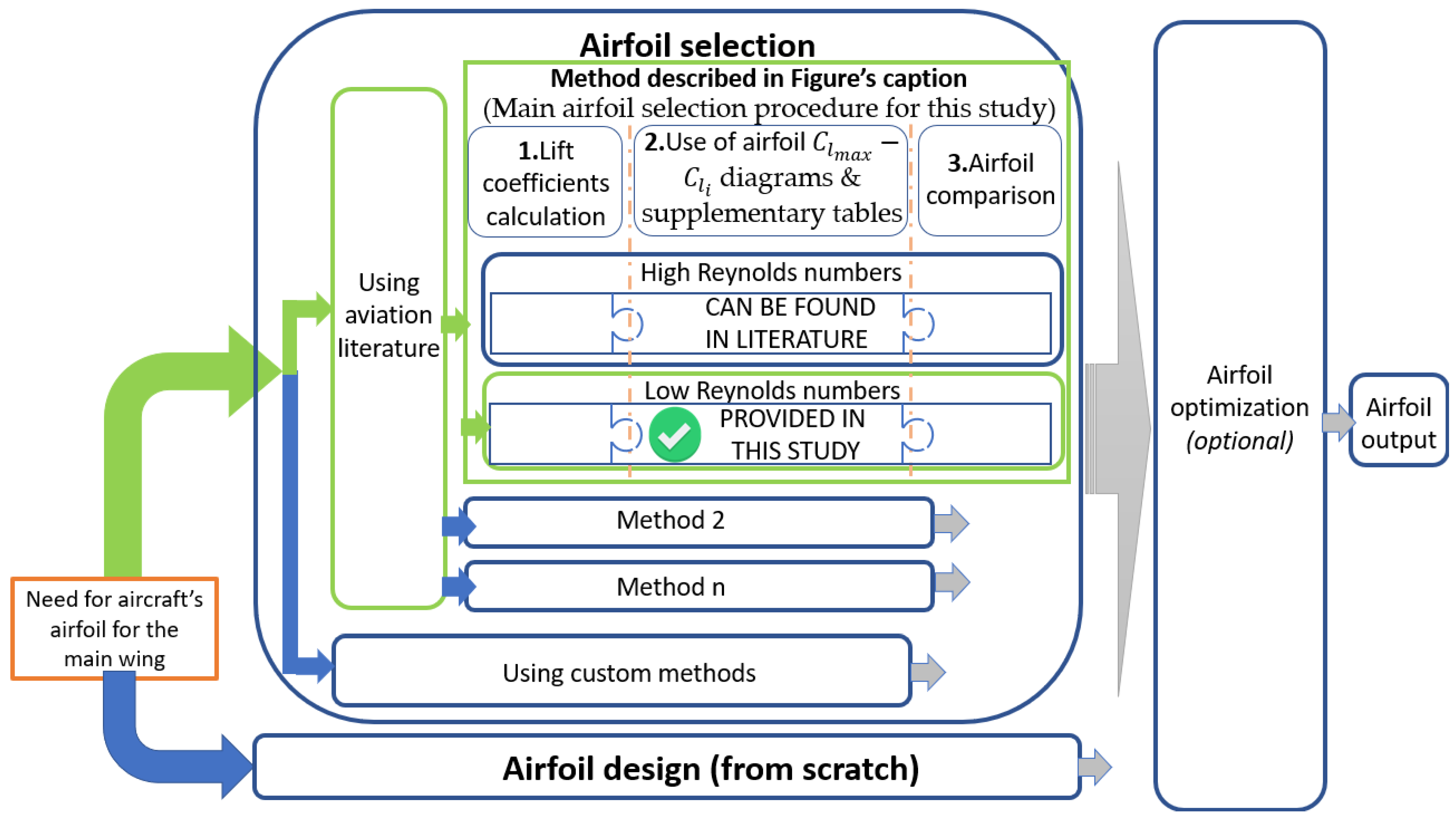
3. Main Airfoil Selection Procedure Description
3.1. Lift Coefficients Calculation
3.2. Use of Airfoil Diagrams and Supplementary Tables
3.3. Airfoil Comparison
4. Materials and Methods
4.1. Literature Review in Low Reynolds Number Airfoils for Small UAV’s
4.2. Selection of Adequate Number of Airfoils for Later Processing
4.3. .dat File Construction with the Polars of Each Airfoil
4.4. Construction of a Clone File of Each Airfoil and Integration of Trailing Edge Flap
4.5. Defining XFLR5 Simulation Parameters and Creation of .xfl Files
4.6. XFLR5 Simulations
5. Results
5.1. Results Export from XFLR5 and Import to Spreadsheet Software
- Minimum drag coefficient Cdmin: Is the minimum Cd value in the Cd-Cl diagram (Units: dimensionless);
- «bucket width» Clbucket_width: the authors thought that it could be useful to conduct a series of measurements under the Clbucket_width name. It is observed that regarding the classic airfoils, such as the NACA series, the bucket always has a smaller width compared to the low Reynolds number airfoils, where the bucket is more spread out in the x axis. An example is demonstrated in Figure 6, where the SG6043 low Reynolds number airfoil is simulated at Re = 350,000, contrary to a classic NACA 662-415 at Re = 3,000,000. The low Reynolds number-widened bucket, is an excellent advantage both for the designer and the operator of the SUAV, as the possible suitable airfoils are increased for the designer and the deviation margin in the flight envelope is also bigger for the operator, without a big penalty in the range and the endurance of the vehicle. (Units: dimensionless);
- Ideal lift coefficient Cli: It corresponds to the minimum drag coefficient. When studying an ideal airfoil with a symmetric bucket, Cli should be in the middle of the bucket. In the real world, Cli can be anywhere close to the curve that we consider as the bucket. (Units: dimensionless);
- Ideal angle of attack αi: Is the angle of attack that corresponds to Cli. (Units: degrees);
- Pitching moment coefficient Cm: The Variations of Pitching Moment Coefficient versus Angle of Attack. The design objective is to have Cm close to zero as far as possible. (Units: 1/rad);
- (Cl/Cd)max: Is the maximum value of the Cd/Cl-α diagram. Large values are desirable. (Units: dimensionless);
- Stall angle αs: Is the critical angle of attack beyond which the airfoil will suffer a decrease in lift force. Large values are desirable, especially at lower Reynolds numbers and when using flaps. (Units: degrees);
- Airfoil gross maximum lift coefficient Clmaxg: It corresponds to the maximum Cl value on a Cl-α diagram. (Units: dimensionless);
- Stall quality: It is a prediction of what is going to happen in the uncomfortable situation where the airfoil will enter the stall region. More details on the stall quality judgment procedure can be found in the next Section 5.2. (Units: Likert 1–5 scale, where: 1 corresponds to the worst stall quality, while score 5 corresponds to excellent stall quality behavior);
- Flap deflection lift coefficient difference ΔCLf: It exclusively relates to the flap deflection data (Table 9). It is synonymous with ΔClHLD. It measures the difference in lift coefficients between the flap and absence of flap deflection. (Units: dimensionless);
- Clmax: Is the maximum lift coefficient, calculated by Clmax = (Clmaxg − ΔLf). (Units: dimensionless).
5.2. Airfoil Stall Quality Judgement
- Real under study points are close to each other so inaccuracy will appear in the measurements;
- Real simulation curves sometimes exhibit secondary or/and tertiary fluctuations (for example, while a curve seems to fade steeply, then it is being regularized, or vice versa.
5.3. Construction of the Airfoil «Map-Diagram»
- It introduces two different Reynolds numbers across the two axes, instead of one. Clmax is calculated at Re = 100,000, while Cli at Re = 200,000;
- Aside of the points that represent each airfoil, a faded line appears to the left and/or right of each point. This line represents the bucket width variable that we discussed earlier.
- The big bucket widths are now visually verified;
- The Cli points’ position is not mandatory to be in the middle of the bucket. The exact position has to do with the physical shape that the bucket has each time;
- The four airfoils (S1123, FX63-137, MH114 and SG6043) that appear at the upper part of the diagram (those with high Clmax), are indeed characterized by their designers as High Lift, Human power aircraft airfoil, Ultralight Airfoil, and High L/D, respectively (see Table 5). All of these airfoils are of high camber. In combination with Table 9, ΔCLf measurement, it can be stated that flap deflection does not have a great effect on the lift coefficient improvement of those high camber airfoils. The S8064 airfoil which has the lowest Clmax is a counterexample, as it is characterized by its designer as a fast RC aircraft;
- Cli dispersion is located around the 0.5–0.6 region and Clmax dispersion is located around the 0.9–1 region.
6. Conclusions
Supplementary Materials
Author Contributions
Funding
Institutional Review Board Statement
Informed Consent Statement
Data Availability Statement
Conflicts of Interest
Abbreviations
| CAA | Civil Aviation Authority |
| CASA | Civil Aviation Safety Authority |
| CFD | Computational Fluid Dynamics |
| FDM | Flight Dynamics Model |
| L/D | Lift to Drag ratio |
| MTOM | Maximum Take Off Mass |
| NACA | National Advisory Committee for Aeronautics |
| PLA | Polylactic Acid |
| RC | Remote Controlled |
| SUAV | Small Unmanned Aerial Vehicle |
| UAS | Unmanned Aerial Systems |
| UAV | Unmanned Aerial Vehicle |
| VTOL | Vertical Take-Off and Landing |
References
- Austin, R. Unmanned Aircraft Systems: UAVs Design, Development and Deployment; AIAA Education Series; American Institute of Aeronautics and Astronautics: Reston, VA, USA, 2010; ISBN 978-1-60086-759-0. [Google Scholar]
- Elston, J.; Argrow, B.; Stachura, M.; Weibel, D.; Lawrence, D.; Pope, D. Overview of Small Fixed-Wing Unmanned Aircraft for Meteorological Sampling. J. Atmos. Ocean. Technol. 2015, 32, 97–115. [Google Scholar] [CrossRef]
- Chianucci, F.; Disperati, L.; Guzzi, D.; Bianchini, D.; Nardino, V.; Lastri, C.; Rindinella, A.; Corona, P. Estimation of Canopy Attributes in Beech Forests Using True Colour Digital Images from a Small Fixed-Wing UAV. Int. J. Appl. Earth Obs. Geoinf. 2016, 47, 60–68. [Google Scholar] [CrossRef]
- Zhang, H.; Wang, L.; Tian, T.; Yin, J. A Review of Unmanned Aerial Vehicle Low-Altitude Remote Sensing (UAV-LARS) Use in Agricultural Monitoring in China. Remote Sens. 2021, 13, 1221. [Google Scholar] [CrossRef]
- Yang, X.; Pei, X. Hybrid System for Powering Unmanned Aerial Vehicles: Demonstration and Study Cases. In Hybrid Technologies for Power Generation; Elsevier: Amsterdam, The Netherlands, 2022; pp. 439–473. ISBN 978-0-12-823793-9. [Google Scholar]
- Smith, H.; Rajendran, P. Review of the Elementary Aspect of Small Solar-Powered Electric Unmanned Aerial Vehicles. AENSI J. 2014, 8, 252–259. [Google Scholar]
- Maddalon, J.; Hayhurst, K.; Koppen, D.; Upchurch, J.; Morris, T.; Verstynen, H. Perspectives on Unmanned Aircraft Classification for Civil Airworthiness Standards; Langley Research Center, National Aeronautics and Space Administration: Hampton, VA, USA, 2013.
- Sadraey, M.H. Aircraft Design: A Systems Engineering Approach; Aerospace Series; Wiley: Chichestet, UK, 2013; ISBN 978-1-119-95340-1. [Google Scholar]
- Eppler, R. Airfoil Design and Data; Springer: Berlin/Heidelberg, Germany, 1990; ISBN 978-3-662-02648-9. [Google Scholar]
- Li, J.; Zhang, M.; Tay, C.M.J.; Liu, N.; Cui, Y.; Chew, S.C.; Khoo, B.C. Low-Reynolds-Number Airfoil Design Optimization Using Deep-Learning-Based Tailored Airfoil Modes. Aerosp. Sci. Technol. 2022, 121, 107309. [Google Scholar] [CrossRef]
- Du, X.; He, P.; Martins, J.R.R.A. Rapid Airfoil Design Optimization via Neural Networks-Based Parameterization and Surrogate Modeling. Aerosp. Sci. Technol. 2021, 113, 106701. [Google Scholar] [CrossRef]
- Yonekura, K.; Miyamoto, N.; Suzuki, K. Inverse Airfoil Design Method for Generating Varieties of Smooth Airfoils Using Conditional WGAN-Gp. Struct. Multidiscip. Optim. 2022, 65, 173. [Google Scholar] [CrossRef]
- Panagiotou, P.; Yakinthos, K. Aerodynamic Efficiency and Performance Enhancement of Fixed-Wing UAVs. Aerosp. Sci. Technol. 2020, 99, 105575. [Google Scholar] [CrossRef]
- Bras, M.; Warwick, S.; Suleman, A. Aeroelastic Evaluation of a Flexible High Aspect Ratio Wing UAV: Numerical Simulation and Experimental Flight Validation. Aerosp. Sci. Technol. 2022, 122, 107400. [Google Scholar] [CrossRef]
- Akbari, V.; Naghashzadegan, M.; Kouhikamali, R.; Afsharpanah, F.; Yaïci, W. Multi-Objective Optimization and Optimal Airfoil Blade Selection for a Small Horizontal-Axis Wind Turbine (HAWT) for Application in Regions with Various Wind Potential. Machines 2022, 10, 687. [Google Scholar] [CrossRef]
- Gray, A.; Singh, B.; Singh, S. Low Wind Speed Airfoil Design for Horizontal Axis Wind Turbine. Mater. Today Proc. 2021, 45, 3000–3004. [Google Scholar] [CrossRef]
- Rojas, C.L.P.; Suarez, C.A.T.; Rico, J.C.S.; Serrano, E.G.F. Airfoil Optimization for Small Horizontal Axis Wind Turbine. In Proceedings of the 19th International Conference on Renewable Energies and Power Quality (ICREPQ’21), Grenada, Spain, 28–30 July 2021; Volume 19, pp. 505–510. [Google Scholar] [CrossRef]
- Gur, O. Airfoil Importance for Propeller Optimized Design. In Proceedings of the 56th 3AF International Conference on Applied Aerodynamics for Lower Environmental Impact, Toulouse, France, 28–30 March 2022. [Google Scholar]
- Wang, F.P.; Xu, Y.; Zhang, G.Q.; Zhang, K. Aerodynamic Optimal Design for a Glider with the Supersonic Airfoil Based on the Hybrid MIGA-SA Method. Aerosp. Sci. Technol. 2019, 92, 224–231. [Google Scholar] [CrossRef]
- Zhang, J.; Li, S.; Xing, Z.; Zhao, J. Aerodynamic Analysis and Airfoil Selection for Flexible Flapping Wings Driven by Dielectric Elastomer. In Proceedings of the 2019 IEEE International Conference on Real-time Computing and Robotics, Irkutsk, Russia, 4–9 August 2019; pp. 237–242. [Google Scholar]
- Sadraey, M.H. Design of Unmanned Aerial Systems; Aerospace Series; John Wiley & Sons: Hoboken, NJ, USA, 2020; ISBN 978-1-119-50862-5. [Google Scholar]
- Gudmundsson, S. General Aviation Aircraft Design: Applied Methods and Procedures, 2nd ed.; Butterworth-Heinemann: Oxford, UK, 2022; ISBN 978-0-12-822647-6. [Google Scholar]
- Raymer, D.P. Aircraft Design: A Conceptual Approach; AIAA Education Series; American Institute of Aeronautics and Astronautics: Reston, VA, USA, 2018; ISBN 978-1-62410-490-9. [Google Scholar]
- Shams, T.A.; Shah, S.I.A.; Javed, A.; Hamdani, S.H.R. Airfoil Selection Procedure, Wind Tunnel Experimentation and Implementation of 6DOF Modeling on a Flying Wing Micro Aerial Vehicle. Micromachines 2020, 11, 553. [Google Scholar] [CrossRef]
- Hassanalian, M.; Quintana, A.; Abdelkefi, A. Morphing and Growing Micro Unmanned Air Vehicle: Sizing Process and Stability. Aerosp. Sci. Technol. 2018, 78, 130–146. [Google Scholar] [CrossRef]
- Boutemedjet, A.; Samardžić, M.; Rebhi, L.; Rajić, Z.; Mouada, T. UAV Aerodynamic Design Involving Genetic Algorithm and Artificial Neural Network for Wing Preliminary Computation. Aerosp. Sci. Technol. 2019, 84, 464–483. [Google Scholar] [CrossRef]
- Semotiuk, L.; Jozwik, J.; Kukielka, K.; Dziedzic, K. Design and FEM Analysis of an Unmanned Aerial Vehicle Wing. In Proceedings of the 2021 IEEE 8th International Workshop on Metrology for AeroSpace (MetroAeroSpace), Naples, Italy, 23–25 June 2021; pp. 365–370. [Google Scholar]
- López, N.S.; Santamaría, A.M.; Castro, S.G. Preliminary Aerodynamic Design and Load Calculation of a Long-Range EVTOL Aircraft. In Proceedings of the AIAA SCITECH 2022 Forum, San Diego, CA, USA, 3–7 January 2022. [Google Scholar]
- Bakar, A.; Ke, L.; Liu, H.; Xu, Z.; Wen, D. Design of Low Altitude Long Endurance Solar-Powered UAV Using Genetic Algorithm. Aerospace 2021, 8, 228. [Google Scholar] [CrossRef]
- Orbea, D.; Moposita, J.; Aguilar, W.G.; Paredes, M.; Reyes, R.P.; Montoya, L. Vertical Take off and Landing with Fixed Rotor. In Proceedings of the 2017 CHILEAN Conference on Electrical, Electronics Engineering, Information and Communication Technologies (CHILECON), Pucon, Chile, 18–20 October 2017; pp. 1–6. [Google Scholar]
- Aboelezz, A.; Hassanalian, M.; Desoki, A.; Elhadidi, B.; El-Bayoumi, G. Design, Experimental Investigation, and Nonlinear Flight Dynamics with Atmospheric Disturbances of a Fixed-Wing Micro Air Vehicle. Aerosp. Sci. Technol. 2020, 97, 105636. [Google Scholar] [CrossRef]
- Mathioudakis, N.; Panagiotou, P.; Kaparos, P.; Yakinthos, K. A Genetic Algorithm Based Method for the Airfoil Optimization of a Tactical Blended-Wing-Body UAV. In Proceedings of the 2020 International Conference on Unmanned Aircraft Systems (ICUAS), Athens, Greece, 1–4 September 2020; pp. 1582–1589. [Google Scholar]
- Goetzendorf-Grabowski, T.; Rodzewicz, M. Design of UAV for Photogrammetric Mission in Antarctic Area. Proc. Inst. Mech. Eng. Part G J. Aerosp. Eng. 2017, 231, 1660–1675. [Google Scholar] [CrossRef]
- Ashraf, A.; Goda, I.; Abdalla, M.M. A Simple Optimization Technique Using Matlab for Small Wind Turbine Blades. In Proceedings of the 2020 6th IEEE International Energy Conference (ENERGYCon), Tunis, Tunisia, 28 September–1 October 2020; pp. 423–428. [Google Scholar]
- Mitchell, D.G. Fifty Years of the Cooper-Harper Scale. In Proceedings of the AIAA Scitech 2019 Forum, San Diego, CA, USA, 7–11 January 2019. [Google Scholar]
- Deperrois, A. XFLR5 Analysis of Foils and Wings Operating at Low Reynolds Numbers 2009. Available online: https://engineering.purdue.edu/~aerodyn/AAE333/FALL10/HOMEWORKS/HW13/XFLR5_v6.01_Beta_Win32%282%29/Release/Guidelines.pdf (accessed on 14 March 2022).
- Drela, M. XFOIL: An Analysis and Design System for Low Reynolds Number Airfoils; Springer: Berlin/Heidelberg, Germany, 1989; pp. 1–12. [Google Scholar]
- Morgado, J.; Vizinho, R.; Silvestre, M.A.R.; Páscoa, J.C. XFOIL vs CFD Performance Predictions for High Lift Low Reynolds Number Airfoils. Aerosp. Sci. Technol. 2016, 52, 207–214. [Google Scholar] [CrossRef]
- Arshad, A.; Rodrigues, L.B.; López, I.M. Design Optimization and Investigation of Aerodynamic Characteristics of Low Reynolds Number Airfoils. Int. J. Aeronaut. Space Sci. 2021, 22, 751–764. [Google Scholar] [CrossRef]
- Jin, W.; Lee, Y.-G. Drag Reduction Design for a Long-Endurance Electric Powered UAV. Int. J. Aeronaut. Space Sci. 2015, 16, 311–324. [Google Scholar] [CrossRef]
- Sánchez, G.G.; Ampáran, J.N.; Beltrán, G.F.; Serrano, X.C.; Ortega, K.O. Aerodynamic and Control Analysis for an Unmanned Aircraft; IOS Press: Amsterdam, The Netherlands, 2017; Volume 295, pp. 143–150. [Google Scholar] [CrossRef]
- Ma, R.; Liu, P. Numerical Simulation of Low-Reynolds-Number and High-Lift Airfoil S1223. In Proceedings of the World Congress on Engineering; International Association of Engineers, London, UK, 7–9 July 2009; Volume 2. [Google Scholar]
- Ngo, K.H.; Huynh, T.L. Airfoil Selection for Fixed Wing of Small Unmanned Aerial Vehicles. In AETA 2015: Recent Advances in Electrical Engineering and Related Sciences; Lecture Notes in Electrical Engineering; Duy, V.H., Dao, T.T., Zelinka, I., Choi, H.-S., Chadli, M., Eds.; Springer: Cham, Switzerland, 2016; Volume 371, pp. 881–890. ISBN 978-3-319-27245-0. [Google Scholar]
- Williamson, G.; McGranahan, B.; Broughton, B.; Deters, R.; Brandt, J.; Selig, M. Summary of Low-Speed Airfoil Data; Department of Aerospace Engineering University of Illinois at Urbana-Champaign: Champaign, IL, USA, 2012. [Google Scholar]
- Selig, M.S.; Guglielmo, J.J.; Broeren, A.P.; Giguere, P. Summary of Low Speed Airfoil Data. 2; SoarTech Publications: Virginia Beach, VA, USA, 1996; ISBN 978-0-9646747-2-1. [Google Scholar]
- Kusznir, T.; Smoczek, J. Particle Swarm Based Airfoil Optimization for SUAV’s Operating in a Low Range of Reynold’s Number. In Proceedings of the 2017 22nd International Conference on Methods and Models in Automation and Robotics (MMAR), Miedzyzdroje, Poland, 28–31 August 2017; pp. 258–262. [Google Scholar]
- Alulema, V.H.; Valencia, E.A.; Pillajo, D.; Jacome, M.; Lopez, J.; Ayala, B. Degree of Deformation and Power Consumption of Compliant and Rigid-Linked Mechanisms for Variable-Camber Morphing Wing UAVs. In Proceedings of the AIAA Propulsion and Energy 2020 Forum, Virtual, 24–26 August 2020. [Google Scholar]
- Selig, M.S.; Gopalarathnam, A. New Airfoils for R/C Sailplanes. Sailplane Electr. Modeler 1997, 2, 14–17. [Google Scholar]


| UAV Characteristic | Description |
|---|---|
| Wingspan | 2 m |
| Main wing geometry | Straight Trailing Edge, geometrically twisted, with winglets and flaps |
| Main wing area | 0.35 m2 |
| Fuselage length | 1.15 m |
| Maximum Take Off Mass (MTOM) | 2 kg |
| Aircraft structure materials | Low density 3D Printed PolyLactic Acid (PLA) and carbon fiber |
| Payload mass | 150 g (camera) |
| Propulsion | Electric |
| Range | 10 km |
| Stall Velocity (Vs) | 9 m/s |
| Cruise Velocity (Vc) | 15 m/s |
| Max Velocity (Vmax) | 30 m/s |
| Launch type | Hand launched |
| Landing type | Belly landing |
| Computational Parameters | Variable’s Name | Equations | |
|---|---|---|---|
| Aircraft | Aircraft ideal lift coefficient during cruise | ||
| Aircraft maximum lift coefficient during take off | |||
| Wing | Wing required lift coefficient during cruise | ||
| Wing maximum lift coefficient during take off | |||
| Airfoil | Airfoil ideal lift coefficient during cruise | ||
| Airfoil gross maximum lift coefficient during take off | |||
| Airfoil net maximum lift coefficient during take off |
| Characteristic | Preference | Re | Weight (%) |
|---|---|---|---|
| Clmax | High values are preferred, within area of interest | 100,000 using flaps | 5 |
| Cli | Preferred are those airfoils whose Cli is nearest to the calculated Cli. | 200,000 | 5 |
| Cdmin | Airfoil with minimum drag coefficient is preferred | 50%: 200,000 50%: 350,000 | 10 |
| (Cl/Cd)max | Airfoil with maximum lift to drag ratio is preferred (Re = 200,000). | 200,000 | 5 |
| Cm | Airfoil with minimum (negative or positive) pitching moment coefficient is preferred (33.3% for each re Red) | 33.3%: 100,000 33.3%: 200,000 33.3%: 350,000 | 10 |
| Stall quality | Manipulatable stall airfoils are preferred. | 15%: 100,000 10%: 200,000 5%: 350,000 70%: 100,000 with flaps | 20 |
| Stall angle of attack | High values are preferred. | 15%: 100,000 10%: 200,000 5%: 350,000 70%: 100,000 with flaps | 30 |
| Bucket width | Airfoils with large bucket width are preferred. | 200,000 | 15 |
| Total: | 100 | ||
| Velocities | Typical Values for SUAV (m/s) | Reynolds Number for the Simulation |
|---|---|---|
| Stall velocity Vs ≈ VTO | 9 | 100,000 |
| Cruise velocity Vc | 15 | 200,000 |
| Maximum velocity Vmax | 30 | 350,000 |
| ID | Airfoil Name | Designer(s) | Reference | Special Attributes | Plot |
|---|---|---|---|---|---|
| 1 | SG6043 | Selig/Giguere | [39] | High L/D |  |
| 2 | SD7032 | Selig/Donovan | [40] | Low Reynolds |  |
| 3 | FX63-137 | F.X. Wortman | [40,41,42] | Human power aircraft airfoil |  |
| 4 | CAL2263M | Cristopher Lyon | [43,44] | CLARK-Y Derivative |  |
| 5 | CAL1215j | Cristopher Lyon | [44] | CLARK-Y Derivative |  |
| 6 | S8064 | Michael Selig | [44] | Fast RC Aircraft |  |
| 7 | S9000 | Michael Selig | [44] | RC sailplane |  |
| 8 | S1223 | Michael Selig | [42,44,45] | High Lift |  |
| 9 | SD7037 | Selig/Donovan | [43,45] | RC Glider airfoil |  |
| 10 | CLARK Y | Virginius E. Clark | [46] | Legacy GA Airfoil used in RC Applications |  |
| 11 | E201 | Richard Eppler | [47] | Low Reynolds |  |
| 12 | E205 | Richard Eppler | [33] | Low Reynolds |  |
| 13 | MH114 | Martin Hepperle | [41] | Ultralight Airfoil |  |
| 14 | SA7038 | Selig/Ashok Gopalarathnam | [48] | RC Sailplane Airfoil |  |
| 15 | E387 | Richard Eppler | [38] | Low Reynolds |  |
| 16 | CR-001 | Cody Robertson | [45] | Hand Launch RC Airfoil |  |
| 17 | MH32 | Martin Hepperle | [45] | RC Sailplane Airfoil |  |
| 18 | S4083 | Michael Selig | [45] | Hand Launch RC Airfoil |  |
| 19 | S7075 | Michael Selig | [45] | RC Airfoil |  |
| 20 | E214 | Richard Eppler | [42] | Low Reynolds number airfoil |  |
| Re = 100,000 (No Flaps) | ||||||||||
|---|---|---|---|---|---|---|---|---|---|---|
| ID | Airfoil | Cdmin | Clbucket_width | Cli | αi | Cm | (Cl/Cd)max | αs | Clmaxg | Stall Quality Scale: 1–5 5: Excellent |
| 1 | SG6043 | 0.019 | 0.94 (0.46–1.4) | 0.84 | 3.1 | −0.14 | 66 | 14 | 1.61 | 1.67 |
| 2 | SD7032 | 0.016 | 0.84 (0.16–1) | 0.64 | 2 | −0.09 | 55 | 11 | 1.38 | 2.33 |
| 3 | FX63-137 | 0.025 | 0.9 (0.3–1.2) | 0.7 | 0 | −0.17 | 63 | 11 | 1.66 | 4.33 |
| 4 | CAL2263M | 0.019 | 1.1 (0–1.1) | 0.6 | 2 | −0.07 | 53 | 14 | 1.34 | 1 |
| 5 | CAL1215j | 0.016 | 0.75 (0–0.75) | 0.45 | 1.3 | −0.07 | 51 | 13 | 1.21 | 1.67 |
| 6 | S8064 | 0.025 | 0.5 (0.15–0.65) | 0.4 | 3.3 | −0.028 | 47 | 10 | 0.98 | 1.67 |
| 7 | S9000 | 0.013 | 0.22 (0.48–0.7) | 0.58 | 2.4 | −0.058 | 53 | 11 | 1.27 | 2 |
| 8 | S1223 | 0.022 | 0 (1.09–1.09) | 1.09 | −0.5 | −0.26 | 52 | 8 | 1.9 | 1.33 |
| 9 | SD7037 | 0.015 | 0.24 (0.59–0.83) | 0.7 | 3.1 | −0.073 | 55 | 10 | 1.26 | 3 |
| 10 | CLARK Y | 0.017 | 0.21 (0.68–0.89) | 0.78 | 3.6 | −0.089 | 53 | 12.5 | 1.36 | 2.33 |
| 11 | E201 | 0.016 | 0.15 (0.2–0.35) | 0.27 | −0.8 | −0.091 | 57 | 11.5 | 1.15 | 2 |
| 12 | E205 | 0.013 | 0.03 (0.17–0.2) | 0.18 | −2 | −0.071 | 55 | 9 | 1.1 | 2 |
| 13 | MH114 | 0.03 | 0.85 (0.5–1.35) | 0.56 | 0 | −0.15 | 49 | 13 | 1.72 | 3.33 |
| 14 | SA7038 | 0.015 | 0.17 (0.65–0.82) | 0.73 | 3.2 | −0.082 | 56 | 10 | 1.3 | 3 |
| 15 | E387 | 0.015 | 0.04 (0.34–0.38) | 0.36 | −0.5 | −0.093 | 60 | 8 | 1.24 | 1.67 |
| 16 | CR-001 | 0.017 | 0.65 (0.35–1) | 0.6 | 1.7 | −0.092 | 64 | 10.5 | 1.34 | 2 |
| 17 | MH32 | 0.015 | 0.8 (0–0.8) | 0.36 | 1 | −0.051 | 53 | 9.5 | 1.08 | 2 |
| 18 | S4083 | 0.011 | 0.08 (0.36–0.44) | 0.4 | 0 | −0.086 | 56 | 10 | 1.23 | 2 |
| 19 | S7075 | 0.018 | 0.6 (0.1–0.7) | 0.42 | 1.3 | −0.067 | 60 | 10.5 | 1.31 | 1.33 |
| 20 | E214 | 0.02 | 0.96 (0.14–1.1) | 0.68 | 2 | −0.098 | 62 | 9.5 | 1.32 | 3.67 |
| Re = 200,000 (No Flaps) | ||||||||||||
|---|---|---|---|---|---|---|---|---|---|---|---|---|
| ID | Airfoil | Cdmin | Clbucket_width | Clbucket_min | Clbucket_max | Cli | αi | Cm | (Cl/Cd)max | αs | Clmaxg | Stall Quality Scale: 1–5 5: Excellent |
| 1 | SG6043 | 0.013 | 1.1 | 0.28 | 1.38 | 0.87 | 1.66 | −0.16 | 98 | 18 | 1.62 | 3.33 |
| 2 | SD7032 | 0.009 | 0.56 | 0.31 | 0.87 | 0.54 | 0.85 | −0.09 | 78 | 11 | 1.4 | 2.67 |
| 3 | FX63-137 | 0.01 | 0.7 | 0.5 | 1.2 | 0.76 | −1 | −0.2 | 89 | 14 | 1.66 | 4.67 |
| 4 | CAL2263M | 0.01 | 0.55 | 0.2 | 0.75 | 0.49 | 0 | −0.1 | 76 | 15 | 1.34 | 1.67 |
| 5 | CAL1215j | 0.01 | 0.52 | 0.12 | 0.64 | 0.41 | 0.87 | −0.068 | 69 | 12 | 1.25 | 2.67 |
| 6 | S8064 | 0.014 | 0.45 | 0.1 | 0.55 | 0.5 | 2.9 | −0.018 | 64 | 10 | 1 | 1.67 |
| 7 | S9000 | 0.0086 | 0.3 | 0.22 | 0.52 | 0.4 | 0.6 | −0.071 | 71 | 11.5 | 1.3 | 3 |
| 8 | S1223 | 0.018 | 0.11 | 1.12 | 1.23 | 1.18 | 1 | −0.27 | 71 | 13 | 2.22 | 3 |
| 9 | SD7037 | 0.009 | 0.2 | 0.4 | 0.6 | 0.51 | 1.23 | −0.083 | 75 | 12 | 1.28 | 3 |
| 10 | CLARK Y | 0.01 | 0.24 | 0.32 | 0.56 | 0.45 | 0 | −0.094 | 73 | 12 | 1.4 | 3 |
| 11 | E201 | 0.01 | 0.12 | 0.21 | 0.33 | 0.27 | −0.6 | −0.076 | 78 | 11.5 | 1.18 | 2 |
| 12 | E205 | 0.009 | 0.07 | 0.15 | 0.22 | 0.18 | −1 | −0.064 | 73 | 11 | 1.13 | 2 |
| 13 | MH114 | 0.013 | 0.15 | 0.85 | 1 | 0.91 | 0.95 | −0.18 | 88 | 13 | 1.74 | 4.67 |
| 14 | SA7038 | 0.092 | 0.14 | 0.44 | 0.58 | 0.51 | 1.04 | −0.087 | 77 | 11 | 1.31 | 2.67 |
| 15 | E387 | 0.0097 | 0.05 | 0.35 | 0.4 | 0.35 | −0.5 | −0.083 | 82 | 10 | 1.25 | 1.67 |
| 16 | CR-001 | 0.0065 | 0.1 | 0.5 | 0.6 | 0.55 | 0.5 | −0.11 | 89 | 11 | 1.36 | 2 |
| 17 | MH32 | 0.0091 | 0.2 | 0.39 | 0.59 | 0.49 | 1.7 | −0.072 | 71 | 9 | 1.07 | 2 |
| 18 | S4083 | 0.0079 | 0.04 | 0.35 | 0.39 | 0.37 | −0.5 | −0.089 | 70 | 9 | 1.22 | 2 |
| 19 | S7075 | 0.0095 | 0.1 | 0.66 | 0.76 | 0.71 | 2.8 | −0.091 | 81 | 13 | 1.38 | 1.67 |
| 20 | E214 | 0.01 | 0.17 | 0.64 | 0.81 | 0.7 | 1.47 | −0.13 | 88 | 10 | 1.33 | 3.67 |
| Re = 350,000 (No Flaps) | ||||||||||
|---|---|---|---|---|---|---|---|---|---|---|
| ID | Airfoil | Cdmin | Clbucket_width | Cli | αi | Cm | (Cl/Cd)max | αs | Clmaxg | Stall Quality Scale: 1–5 5: Excellent |
| 1 | SG6043 | 0.0084 | 0.89 (0.28–1.17) | 0.8 | −0.24 | −0.17 | 126 | 16 | 1.65 | 5 |
| 2 | SD7032 | 0.0067 | 0.54 (0.28–0.82) | 0.44 | 0 | −0.092 | 96 | 12 | 1.45 | 2.67 |
| 3 | FX63-137 | 0.01 | 0.7 (0.5–1.2) | 0.96 | 0.4 | −0.2 | 103 | 14 | 1.69 | 4.67 |
| 4 | CAL2263M | 0.0074 | 0.47 (0.23–0.7) | 0.48 | 0 | −0.097 | 94 | 15 | 1.38 | 4 |
| 5 | CAL1215j | 0.0075 | 0.54 (0.16–0.7) | 0.44 | 1.18 | −0.05 | 82 | 13 | 1.35 | 3.33 |
| 6 | S8064 | 0.009 | 0.3 (0.3–0.6) | 0.5 | 3.5 | −0.03 | 72 | 12 | 1.05 | 2 |
| 7 | S9000 | 0.0066 | 0.35 (0.15–0.5) | 0.33 | 0.2 | −0.066 | 85 | 11.5 | 1.37 | 3 |
| 8 | S1223 | 0.015 | 0.18 (1.07–1.25) | 1.16 | 0 | −0.26 | 87 | 13 | 2.28 | 2 |
| 9 | SD7037 | 0.0064 | 0.12 (0.37–0.49) | 0.42 | 0.4 | −0.08 | 91 | 11 | 1.29 | 3 |
| 10 | CLARK Y | 0.0075 | 0.1 (0.37–0.47) | 0.42 | 0 | −0.082 | 89 | 13 | 1.41 | 3.33 |
| 11 | E201 | 0.008 | 0.18 (0.3–0.48) | 0.38 | 0.3 | −0.076 | 92 | 11 | 1.18 | 2 |
| 12 | E205 | 0.0078 | 0.12 (0.28–0.4) | 0.34 | 0 | −0.06 | 86 | 11 | 1.14 | 2 |
| 13 | MH114 | 0.096 | 0.25 (0.85–1.1) | 0.98 | 1.2 | −0.19 | 116 | 14 | 1.77 | 5 |
| 14 | SA7038 | 0.064 | 0.05 (0.38–0.43) | 0.4 | 0 | −0.083 | 93 | 11 | 1.34 | 3.33 |
| 15 | E387 | 0.007 | 0 (0.34–0.34) | 0.34 | −0.5 | −0.08 | 98 | 9.5 | 1.23 | 2 |
| 16 | CR-001 | 0.065 | 0.09 (0.51–0.6) | 0.55 | 0.25 | −0.11 | 108 | 11.5 | 1.39 | 2.33 |
| 17 | MH32 | 0.0064 | 0.11 (0.32–0.43) | 0.37 | 0.5 | −0.058 | 87 | 8 | 1.04 | 2 |
| 18 | S4083 | 0.0066 | 0.02 (0.37–0.39) | 0.38 | −0.5 | −0.088 | 79 | 8 | 1.17 | 2 |
| 19 | S7075 | 0.0068 | 0.06 (0.56–0.62) | 0.59 | 1.6 | −0.091 | 99 | 13 | 1.47 | 2 |
| 20 | E214 | 0.008 | 0.23 (0.41–0.64) | 0.51 | −0.7 | −0.14 | 109 | 10 | 1.37 | 3.33 |
| Re = 100,000 (Flap @ 80% Chord, 30°) | ||||||
|---|---|---|---|---|---|---|
| ID | Airfoil | Clmaxg | ΔCLf | Clmax | αs | Stall Quality Scale: 1–5 5: Excellent |
| 1 | SG6043 | 1.89 | 0.28 | 1.33 | 11 | 1.67 |
| 2 | SD7032 | 1.73 | 0.35 | 1.03 | 7 | 2 |
| 3 | FX63-137 | 1.76 | 0.1 | 1.56 | 7 | 4 |
| 4 | CAL2263M | 1.72 | 0.38 | 0.96 | 10 | 1.67 |
| 5 | CAL1215j | 1.58 | 0.37 | 0.84 | 9.7 | 2.33 |
| 6 | S8064 | 1.45 | 0.47 | 0.51 | 6 | 1 |
| 7 | S9000 | 1.66 | 0.39 | 0.88 | 6.5 | 2.33 |
| 8 | S1223 | 1.89 | −0.01 | 1.91 | 4 | 1 |
| 9 | SD7037 | 1.65 | 0.39 | 0.87 | 7.5 | 2.33 |
| 10 | CLARK Y | 1.7 | 0.34 | 1.02 | 10 | 3.67 |
| 11 | E201 | 1.57 | 0.42 | 0.73 | 8 | 1.67 |
| 12 | E205 | 1.57 | 0.47 | 0.63 | 6 | 1.67 |
| 13 | MH114 | 2 | 0.28 | 1.44 | 10 | 3.67 |
| 14 | SA7038 | 1.64 | 0.34 | 0.96 | 6 | 3 |
| 15 | E387 | 1.67 | 0.43 | 0.81 | 6 | 1.67 |
| 16 | CR-001 | 1.72 | 0.38 | 0.96 | 6 | 2 |
| 17 | MH32 | 1.55 | 0.47 | 0.61 | 4.5 | 1.33 |
| 18 | S4083 | 1.64 | 0.41 | 0.82 | 6 | 1.67 |
| 19 | S7075 | 1.72 | 0.41 | 0.9 | 6.5 | 1.33 |
| 20 | E214 | 1.6 | 0.28 | 1.04 | 5.7 | 3 |
| Re = 100,000 No Flaps | Re = 200,000 No Flaps | Re = 350,000 No Flaps | Re = 100,000 30% Flaps | |
|---|---|---|---|---|
| Weight | 15% | 10% | 5% | 70% |
| Ranking | Airfoil ID | Airfoil Name | Stall Quality Score | Ranking | Airfoil ID | Airfoil Name | Stall Quality Score |
|---|---|---|---|---|---|---|---|
| 1 | 3 | FX63-137 | 4.15 | 11 | 1 | SG6043 | 2.0025 |
| 2 | 13 | MH114 | 3.7855 | 12 | 11 | E201 | 1.769 |
| 3 | 10 | CLARK Y | 3.385 | 13 | 12 | E205 | 1.769 |
| 4 | 20 | E214 | 3.184 | 14 | 18 | S4083 | 1.769 |
| 5 | 14 | SA7038 | 2.9835 | 15 | 15 | E387 | 1.6865 |
| 6 | 9 | SD7037 | 2.531 | 16 | 4 | CAL2263M | 1.686 |
| 7 | 7 | S9000 | 2.381 | 17 | 17 | MH32 | 1.531 |
| 8 | 5 | CAL1215j | 2.315 | 18 | 19 | S7075 | 1.3975 |
| 9 | 2 | SD7032 | 2.15 | 19 | 8 | S1223 | 1.2995 |
| 10 | 16 | CR-001 | 2.0165 | 20 | 6 | S8064 | 1.2175 |
Publisher’s Note: MDPI stays neutral with regard to jurisdictional claims in published maps and institutional affiliations. |
© 2022 by the authors. Licensee MDPI, Basel, Switzerland. This article is an open access article distributed under the terms and conditions of the Creative Commons Attribution (CC BY) license (https://creativecommons.org/licenses/by/4.0/).
Share and Cite
Kapoulas, I.K.; C. Statharas, J.; Hatziefremidis, A.; Baldoukas, A.K. Fast Airfoil Selection Methodology for Small Unmanned Aerial Vehicles. Appl. Sci. 2022, 12, 9328. https://doi.org/10.3390/app12189328
Kapoulas IK, C. Statharas J, Hatziefremidis A, Baldoukas AK. Fast Airfoil Selection Methodology for Small Unmanned Aerial Vehicles. Applied Sciences. 2022; 12(18):9328. https://doi.org/10.3390/app12189328
Chicago/Turabian StyleKapoulas, Ioannis K., J. C. Statharas, Antonios Hatziefremidis, and A. K. Baldoukas. 2022. "Fast Airfoil Selection Methodology for Small Unmanned Aerial Vehicles" Applied Sciences 12, no. 18: 9328. https://doi.org/10.3390/app12189328
APA StyleKapoulas, I. K., C. Statharas, J., Hatziefremidis, A., & Baldoukas, A. K. (2022). Fast Airfoil Selection Methodology for Small Unmanned Aerial Vehicles. Applied Sciences, 12(18), 9328. https://doi.org/10.3390/app12189328