Article

Electric Motor Control for Online Tuning Based on Positive Flow System for Electric Construction Machinery

1
College of Mechanical Engineering and Automation, Huaqiao University, Xiamen 361021, China
2
Fujian Key Laboratory of Green Intelligent Drive and Transmission for Mobile Machinery, Xiamen 361021, China
3
Shanghai Institute of Special Equipment Inspection and Technical Research, Shanghai 200062, China
*
Author to whom correspondence should be addressed.
Appl. Sci. 2022, 12(19), 10072; https://doi.org/10.3390/app121910072
Submission received: 15 September 2022 / Revised: 30 September 2022 / Accepted: 4 October 2022 / Published: 7 October 2022

Abstract

:
With the increasingly serious environmental pollution and stricter emission standards, energy saving and emission reduction in construction machinery (CM) are imminent. Electrification of CM is an inevitable trend. Due to the complicated working conditions and the violent load fluctuations, the existing motor controller cannot adapt well to the operating characteristics of the electric CM. In this paper, the work requirements of the positive flow system are analyzed. Considering the robustness and resistance to load disturbance of the control system, a vector control strategy through online tuning of speed PI parameters based on fuzzy control is proposed. The characteristics of the control system are analyzed with the co-simulation of AMESim and MATLAB/Simulink. A test rig was set up to verify the feasibility of the control strategy. The results show that when the load is variable, the fluctuation of rotation speed is approximately 1.5% with fuzzy PI, and 2.5% with traditional PI. Furtherly, the vector control algorithm based on fuzzy PI is tested on a positive flow system. The test results show that when the load fluctuates drastically, the electric motor speed fluctuation is within 3.5%, and the steady-state error is only approximately 0.3%.

1. Introduction

As global environmental pollution and energy shortages continue to intensify, green, energy saving, and environmental protection have attracted widespread attention from all over the world [1,2]. Construction machinery (CM) has low energy efficiency and poor emissions, which has gradually been unable to meet the need of the times. Electric CM using a motor instead of an engine can achieve zero emission, and is treated as a major trend in industrial development [3,4].
At present, the electric motor control system is relatively mature [5,6], many advanced control methods are employed [7]. However, due to the complicated working conditions and the violent load fluctuations, the existing motor controller used in the industrial field and other stable load conditions cannot adapt well to the operating characteristics of the CM [8,9]. Research on electric motor control systems based on the CM load characteristics has gradually attracted attention. Control strategies for the electric motor are mainly vector control and direct torque control (DTC). DTC has the advantage of fast dynamic response, but it also has the disadvantage of large torque ripple, poor low-speed performance, and low current utilization [10,11]. Vector control adopts coordinate transformation to equate the mathematical model of the alternating current (AC) motor to the direct current (DC) motor [12,13]. While simplifying the control method, it obtains the control performance comparable to that of the DC motor. Compared with the DTC, the speed regulation range of vector control is wider, the low-speed performance is better, and the current utilization is higher.
The working condition of electric CM is complex. Therefore, special research on its power motor is needed [14]. Chen et al. designed a novel DTC for a permanent magnet synchronous motor (PMSM) in hybrid power train system to reduce the influence of DC voltage on the maximum output torque of the PMSM. The results demonstrated that the proposed DTC can reduce the effect of DC voltage variation on the maximum output torque of the PMSM [15]. Wang et al. employed a segmented Halbach permanent magnet (PM) array for the permanent magnet synchronous generator rotor configuration for the PMSM structure. The results showed that this method effectively improved the energy-saving efficiency of the hydraulic system [16]. Hoai et al. proposed a novel type of sliding mode controller that combines intelligent control and phase-locked loop. Through simulation and experiments, it was verified that the motor control system had the characteristics of smooth switching, good tracking response, and strong anti-interference ability [17]. Elsonbaty et al. proposed a control strategy for a hybrid-excitation salient-pole PMSM in which the armature winding and the DC excitation winding were located on the stator at the same time. The simulation verified that the control strategy met the motor requirements of electric vehicles and hybrid electric vehicles, and the control strategy had superior responsiveness and robustness [18]. Currently, the development of AC motor control strategies mostly makes simple improvements on traditional control strategies, without analyzing the working conditions of CM [19]. The traditional vector control adopts the PI controller for closed-loop regulator design of speed and current [20]. Electric CM has severe load fluctuations and complex working conditions, which is a typical load time-varying system. The fixed PI parameters of traditional control cannot change with the load variation, which results in poor dynamic adjustment ability and poor anti-load disturbance ability of the controller.
Considering the complex working conditions of CM, the PI parameters of the motor controller should be adjusted in real time according to the characteristics of CM working conditions. PI parameter online tuning technology mainly includes online tuning based on model parameters and intelligent algorithms [21]. Online tuning based on model parameters can identify the control system parameters under dynamic working conditions. Combining with the system mathematical model, online tuning formulas can adjust and update the PI controller parameters in real time. Though the online tuning technology based on the intelligent algorithm is complicated and large amount of calculation is needed, its algorithm is relatively simple and highly targeted. Therefore, due to its powerful computing power and strong self-adjustment ability, the online tuning effect is significantly better than the online tuning technology based on model parameters. With the rapid development of computer technology and intelligent algorithms, online tuning technology based on model parameters is gradually being replaced by that based on intelligent algorithms [22].
To provide full play to the superior speed regulation characteristics and flow matching characteristics of CM electric power system, a typical positive flow system in CM is taken as the application object, the motor vector control system based on fuzzy control of the speed PI parameter online tuning is proposed. This paper is organized as follows: In Section 2, mathematical model analysis of PMSM and positive flow system is presented. Design of electric motor control strategy and regulators is introduced in Section 3. Simulation analysis and experiments verification under different conditions are shown in Section 4 and Section 5, respectively. Finally, the conclusion is obtained.

2. Mathematical Model Analysis

To make the motor control strategy better adapt to the load characteristics of electric CM, the mathematical model of a PMSM and a positive flow system of CM is analyzed. Through the mathematical model of the positive flow system, the requirements for speed and torque output characteristics of the PMSM are studied.

2.1. Mathematical Model of PMSM

Among different motors, PMSM has the advantages of small size, easy maintenance, high power density, and good speed regulation performance, which is widely used in electric vehicles [23,24]. Therefore, the PMSM is used for the power train system in this study.
The electric motor torque equation in the two-phase synchronous rotating coordinate system can be provided as:
T e = P [ ψ f i q + ( L d L q ) i d i q ]
where subscripts d and q are the components of the d and q axes, respectively, in the rotating coordinate system; i is the stator current; L is the stator inductance; T e is the electromagnetic torque; P is the electric motor pole pairs; and ψ f is the rotor flux.
For surface-mount PMSM, the inductances of the quadrature and straight shafts of the electric motor are approximately equal. The Equation (1) can be rewritten as:
T e = P ψ f i q
In the two-phase rotating coordinate system, the mathematical model of the electric motor is decoupled. Thus, for surface-mounted PMSM, i d = 0 is often used to achieve decoupling control of the quadrature and straight shafts current.
The torque balance equation of the PMSM can be deduced as:
T e = 2 π J P d n d t + 2 π R Ω n P + T l
According to Equations (2) and (3), the relationship between the motor speed and the current of the quadrature and straight shafts can be obtained.

2.2. Mathematical Model of Positive Flow System

The traditional positive flow system applied to a traditional CM uses a variable pump with a constant speed system [1]. Due to the excellent motor speed response, the quantitative pump-variable speed positive flow system was investigated. The principle of the quantitative pump-variable speed positive flow system is shown in Figure 1.
The target speed of the electric motor pump is controlled by the pilot handle output signal. The greater the pilot output signal is, the greater the electric motor speed achieves. To prevent the system from overloading, relief valves are equipped in both chambers of the oil cylinder. A check globe valve is set up to avoid the cylinders falling because of the gravity when the multi-way valve is in the neutral position.
The mathematic model of the hydraulic system is analyzed. To simplify the analysis, some assumptions are provided as:
  • Hydraulic pump inlet pressure, system return pressure, and the tank pressure are assumed to be zero;
  • The relief valve is not set at the pump outlet port. The leakage of hydraulic pump, valves, and actuators is ignored;
  • The flow fluctuation caused by pipeline pressure loss and pipeline friction is not considered.
The output flow equation of the pump can be expressed as:
q V 1 = V 1 n C p p 1
where q V 1 is the pump output flowrate; V 1 is the pump displacement; n is the pump speed; C p is the pump leakage factor; and p 1 is the pump output pressure.
The relationship between the output pressure and the torque of the pump can be deduced as:
p 1 = 2 π T V 1
where T is the pump output torque.
The force balance equation of the globe valve when the cylinder extends is:
p 2 p 3 = k 1 x 1 / A 1
where p 2 is the output pressure of the check valve; p 3 is the pressure of the cylinder in a rodless cavity; k 1 is the elastic coefficient of the globe valve in the spring cavity; x 1 is the spring displacement of the globe valve; and A 1 is the effective area of the globe valve in the spring cavity.
The force balance equation of the globe valve when the cylinder retracts can be provided as:
p 3 p 4 = k 1 x 1 / A 1
where p 4 is the inlet pressure of orifice in the multi-way valve.
The flow equation of orifice in the multi-way valve can be written as:
q V 2 = C q W v X v 2 ρ Δ p
where q V 2 is the flowrate through the orifice; C q is the flow coefficient; W v is the flow area gradient; X v is the orifice opening size; ρ is the oil viscosity; and Δ p is the pressure difference before and after orifice.
The force balance equation of cylinder can be expressed as:
p 3 A 2 = p 4 A 3 + m d v d t + b L v + F
where A 2 is the effective area of the cylinder in a rodless cavity; p 4 is the pressure of the cylinder in a rod cavity; A 3 is the effective area of the cylinder in a rod cavity; m is the mass of the piston and the load converted to the piston; v is the cylinder speed; b L is the viscous damping of the piston and load; and F is the load force.
It can be seen from the mathematical model of the positive flow system that the performance of the pump outlet flowrate is closely related to the electric motor speed performance which directly affects the speed control performance of the positive flow system. Furthermore, pump outlet pressure is closely related to the pump input torque which directly affects the pump output pressure characteristics. Therefore, improvement of the responsiveness and robustness of the electric motor speed, and the stability of the electric motor output torque greatly enhances the controllability of the positive flow system.

3. Control Strategy of Motor Control System

3.1. Control System Overall Scheme

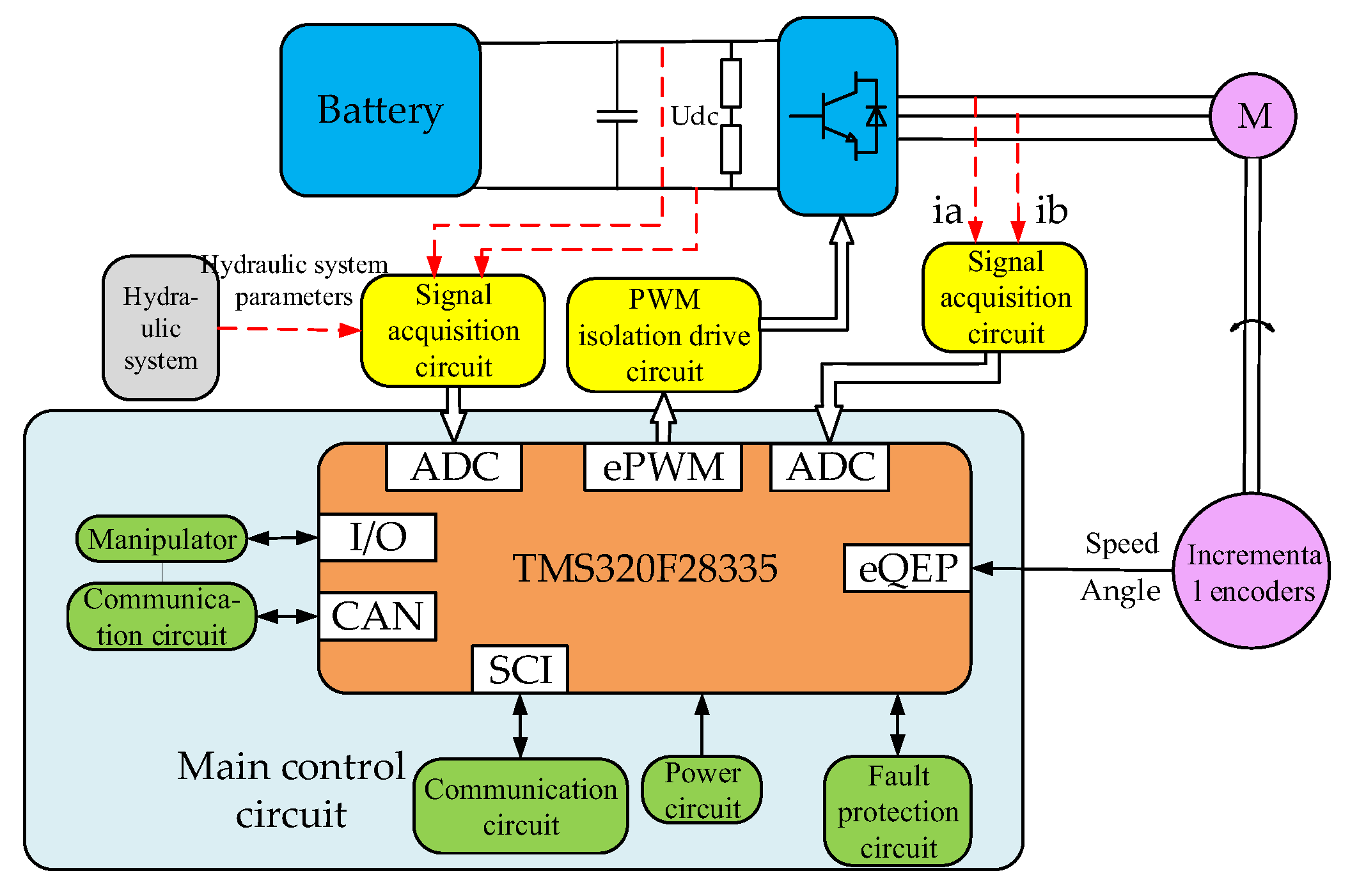
The hardware circuit structure diagram of the PMSM control system is shown in Figure 2 The main control chip adopts the Digital Signal Processing (DSP) chip TMS320F28335 developed by TI company. The control system includes the signal acquisition circuit, the pulse-width modulation (PWM) isolation drive circuit, the communication circuit, the power circuit, and the fault protection circuit, etc.
In the traditional vector control, the current loop is set as the inner loop, and the speed loop is set as the outer loop. Meanwhile, the traditional PI regulator is used to de-sign the current loop and the speed loop. Since the controllability of the positive flow system is closely related to the motor operating performance which directly affects the speed regulation performance of the positive flow system. Improving the responsiveness and robustness of the electric motor speed output is very vital for the positive flow system. Therefore, the vector control strategy scheme based on online tuning of speed PI parameters shown in Figure 3 is proposed by adopting fuzzy PI to observe the speed.

3.2. Closed Loop Regulator Design

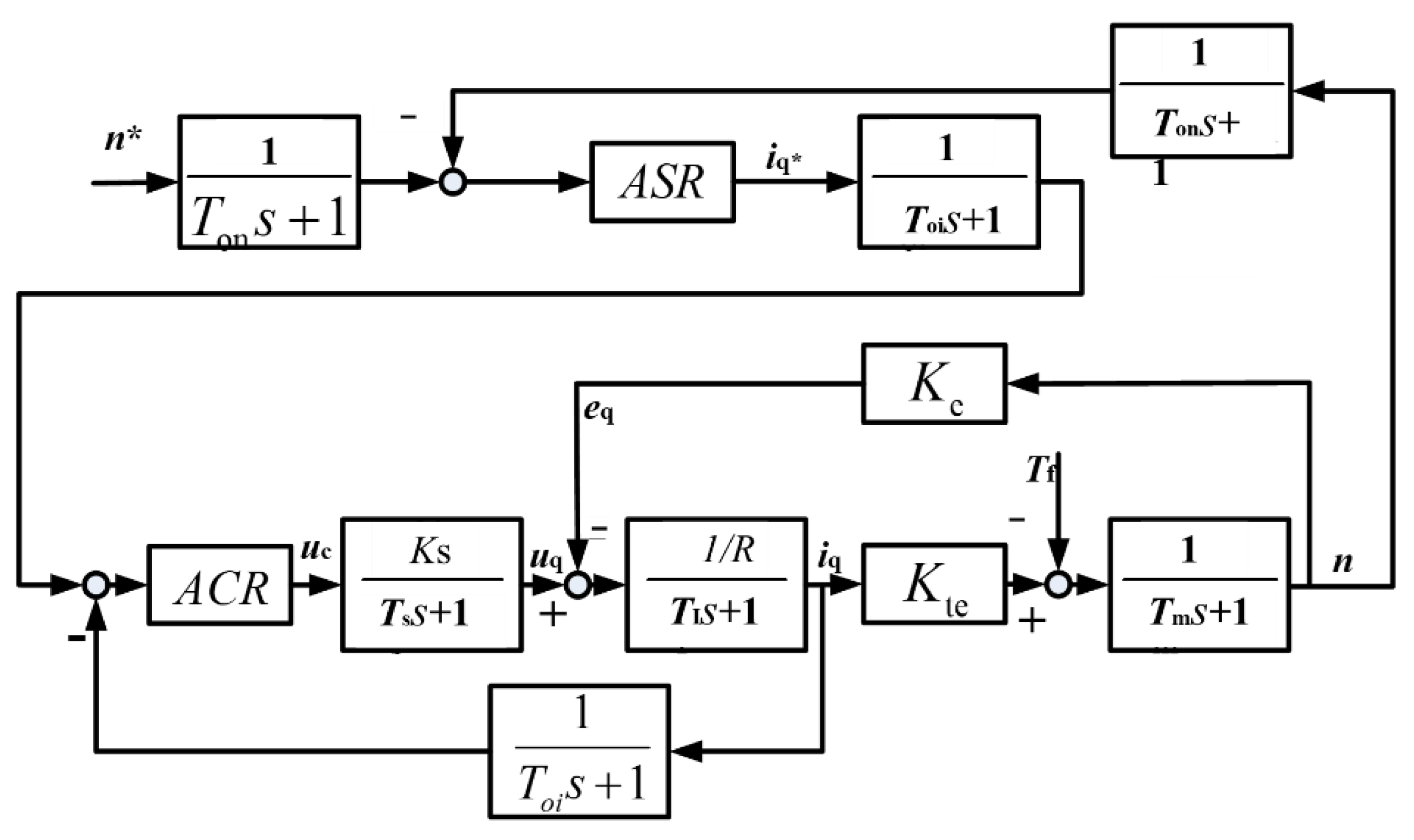
As can be seen in Figure 3, the current loop is designed by traditional PI, the speed loop is designed by fuzzy PI control. The dynamic structure of the PMSM vector control system is shown in Figure 4. Where K t e is the electric motor torque coefficient, K t e = 3 / ( 2 n p ψ f ) ; T m is the mechanical time constant, T m = J · 2 π / 60 ; K e is the electric motor back-EMF coefficient, K e = 2 π / ( 60 n p ψ d ) ; and T 1 is the electric motor armature time constant, T 1 = L q / R . The inverter is equivalent to the first-order inertial loop with an amplification factor of Ks. ACR is Automatic Current Regulator. ASR is Automatic Speed Regulator.
In the case of multiple closed-loop control, the design principle of first inner loop and then outer loop is usually used. Therefore, the current regulator is designed first.

3.2.1. Automatic Speed Regulator (ASR) Design

Since the speed loop is designed with fuzzy PI control, it is necessary to design the speed PI regulator first and calculate the theoretical value of the initial PI parameter. The simplified current loop can be treated as an intermediate link of the speed loop, and its closed-loop transfer function can be simplified as:
G ACR ( s ) = 1 3 T s s + 1
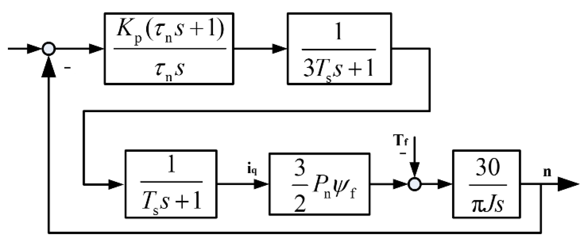
According to Equation (10), the structure of the PMSM vector control system can be simplified as shown in Figure 5.
From Figure 5, the open-loop transfer function of the speed loop is:
G ASR ( s ) = K p ( τ n s + 1 ) τ n s 1 3 T s s + 1 1 t d s + 1 3 2 n p ψ f 30 π J s = 45 n p ψ f K p π J τ n ( τ n s + 1 ) s 2 ( 4 T s s + 1 ) = K ASR ( τ n s + 1 ) s 2 ( 4 T s s + 1 )
where K ASR = 45 n p ψ f K p π J τ n .
According to the Equation (11), the speed loop is a third order system. The system block diagram is shown in Figure 6.
According to the actual object system response and anti-disturbance requirements on the speed, the speed loop should be equivalent to a typical II-type system. As shown in Figure 6, the system has two characteristics:
  • The system contains two pure integration loops, the initial slope of the amplitude-frequency characteristic is −40 dB, and the initial phase angle is −180°;
  • The corner frequency of the system is 1 / ( 4 T s ) in the inertia loop and 1 / τ n in the differential loop.
The intermediate frequency bandwidth is within the range of the differential loop and the integral loop. The intermediate frequency bandwidth determines the system response speed, and the phase margin of the cut-off frequency determines the system stability. For the electric motor control system, the parameter design process is to optimize these two indexes.
The highest point of the phase-frequency curve is the point with the largest phase margin. Meanwhile, this point is also the midpoint of the two-corner frequency. Thus, the calculation formula of the phase margin is:
lg w c = lg 1 4 T s h 2
where h is the intermediate frequency bandwidth.
Then the phase margin is:
w c = 1 4 T s 10 h 2
Because
20 lg K N 40 lg 1 τ n 20 ( lg w c lg 1 τ n ) = 0
Then
w c = K N τ n
Based on the previous analysis, the PI parameter of the speed regulator can be obtained as:
{ K p ( A S R ) = π J 45 T sm 10 h 2 P n ψ f K i ( A S R ) = π J 45 T sm 2 10 3 h 2 P n ψ f
where T s m = 4 T s .

3.2.2. Fuzzy PI Regulator Design

The fuzzy control system takes the deviation, the deviation variation rate, and the variation rate of deviation change as the input of the fuzzy controller. According to the input numbers, fuzzy controllers can be divided into one-dimensional, two-dimensional, and three-dimensional. This paper chose a two-dimensional fuzzy controller as the core of the fuzzy control system.
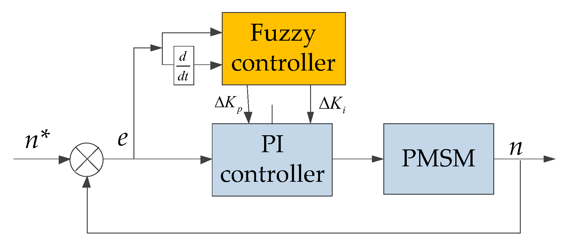
In this paper, there are two inputs of the fuzzy controller. One is the difference between the target speed and the actual speed of the electric motor, and the other one is the change in the difference. The output is the change in the PI parameters, they are Δ K p and Δ K i . It can be concluded that the structure of the online tuning regulator for speed PI parameters of PMSM vector control system is shown in Figure 7. The final expression of the speed PI parameter online tuning regulator is:
{ K p = K p 0 + Δ K p K i = K i 0 + Δ K i
where K p 0 and K i 0 are the initial PI parameters obtained by the engineering method for the mathematical model of PMSM.
To make the fuzzy controller work normally, variables should be defined by fuzzy language. In this paper, fuzzy variables e and e c are defined as:
{ NB , NM , NS , ZO , PS , PM , PB }
where N is negative, B is big, M is middle, S is small, ZO is zero, and P is positive.
According to engineering practice experience, the adjustment function of PI parameters and fuzzy inference rules, the requirements of e and e c for K p and K i can be obtained.
  • When e is large and e > 0 , K p should be increased to make the system output quickly approach the target value, while K i should be reduced to prevent the system from overshooting;
  • When e is large and e < 0 , K p should be appropriately reduced to reduce overshoot, while K i should be increased to eliminate the steady-state error;
  • When e is small and e c is large, K p should be reduced and K i should be appropriately increased;
  • When e is close to zero, K p and K i should be increased appropriately to improve the steady-state accuracy and dynamic characteristics of the system.
According to the characteristics of PI parameters and the above requirements, fuzzy control rules of K p and K i changing for e and e c can be obtained, as shown in Table 1 and Table 2.
The fuzzy controller parameters that are the quantization factor of the input variable and the proportional factor of the output control quantity affects the performance of the system directly. The quantization factor of the input variable and the scale factor of the output control quantity can be expressed as:
{ K e = n x e ; K ec = m x ec K up = y up l p ; K ui = y ui l i
.
The quantization factor of the input variable and the scale factor of the output control value calculated according to Equation (19) are ideal values. In practical application, the specific value of the fuzzy controller parameters should be adjusted according to the actual control effect.

4. Simulation Study

The AMESim-Simulink co-simulation model of the positive flow system was built to verify the control performance. The performance of positive flow system under fuzzy PI control and traditional PI control was compared.
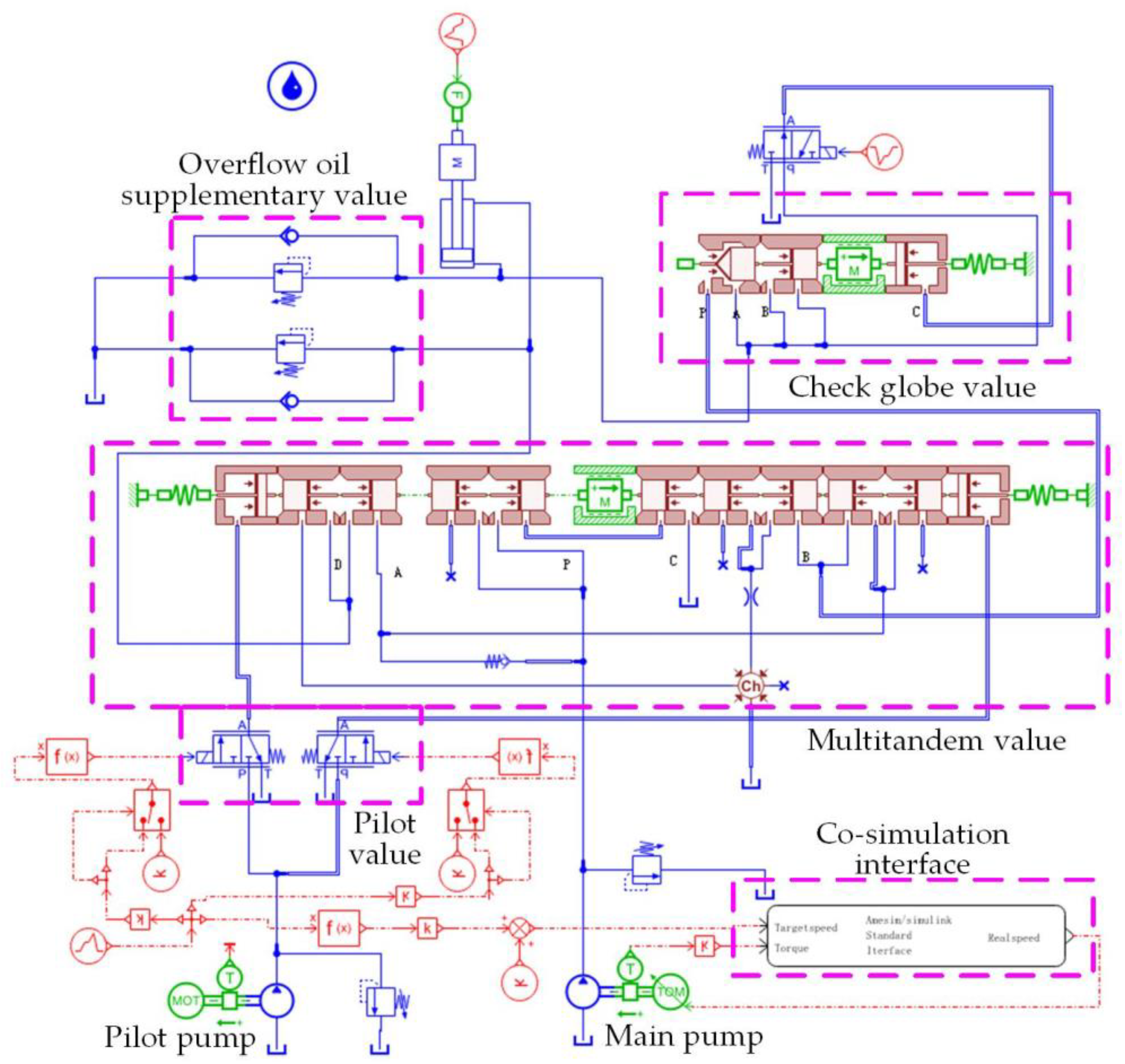
The co-simulation model is shown in Figure 8. The simulation model includes the main pump, the pilot pump, the pilot valve, the multi-way valve, the check globe valve, relief oil supplementary valve, the actuator, the co-simulation interface, etc. The regulator for online tuning of speed PI parameter is designed with a fuzzy PI controller. The controller mainly includes a fuzzy logic controller, a proportional loop, an integral loop, and a speed limiting module.

4.1. Comparison of Traditional PI and Fuzzy PI

The speed responses of the two speed control methods are shown in Figure 9 and Figure 10. When the electric motor starts, the overshoot of the traditional PI control and fuzzy PI control are 12 r/min and 6 r/min, respectively. The time to steady state is 40 ms and 31 ms, respectively. When the speed changed suddenly, the overshoot of the traditional PI control and fuzzy PI control are 8 r/min and 5 r/min, respectively. The time to steady state is 24 ms and 16 ms, respectively. A 15 N·m load is added at 0.2 s, the electric motor speed drop of the traditional PI control and fuzzy PI control are 10 r/min and 6 r/min, respectively. Moreover, the adjustment time is 16 ms and 7 ms, respectively. Therefore, when the fuzzy PI control is used, the motor speed output overshoot is smaller, the response is faster, the load disturbance has less affection, and the stability is higher.
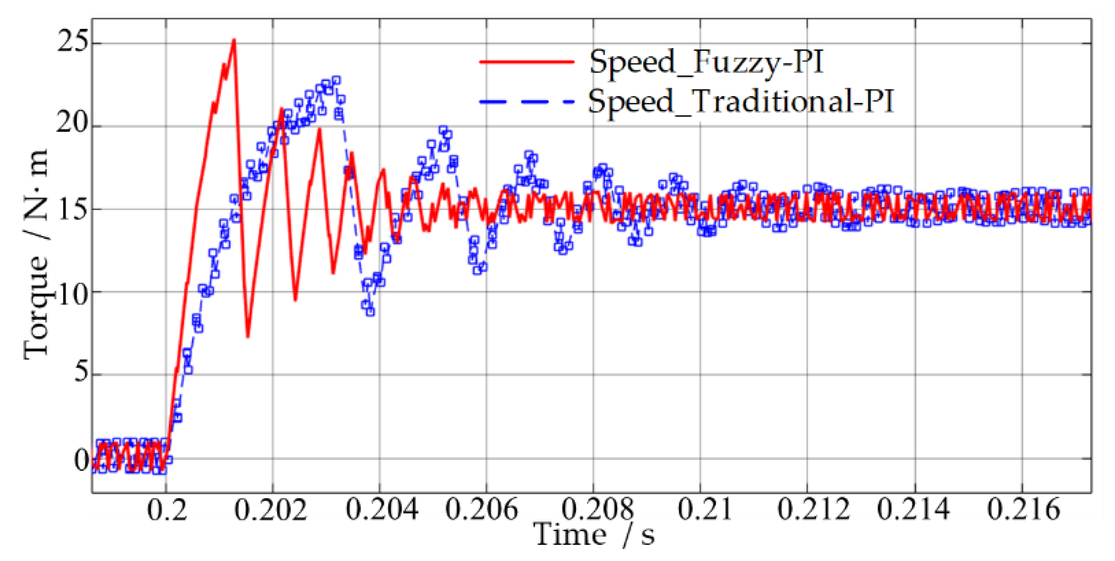
The change curve of the electric motor output torque under load mutation condition is shown in Figure 11. A 15 N·m load is loaded at 0.2 s, the adjustment times of the two control systems are 15 ms and 7 ms, respectively. The torque overshoot of traditional PI control is smaller, but the adjustment time is slower than that of fuzzy PI control. At the same time, the adjustment process of traditional PI control oscillates obviously. Even when the torque reaches the steady state, there are fluctuations. It can be seen that when the fuzzy PI control is used, the electric motor output torque overshoot is slightly increased, but the responsiveness and stability are significantly improved.

4.2. PI Parameter Online Tuning System-Positive Flow System

In the variable speed quantitative pump positive flow system, an electronic control handle is used to achieve pilot signal control. Meanwhile, the output signal of the electronic control handle is converted to the target speed information of the main pump. The simulation process simulates a movement cycle of the boom cylinder of an 8-ton pure electric hydraulic excavator under typical cycle conditions.
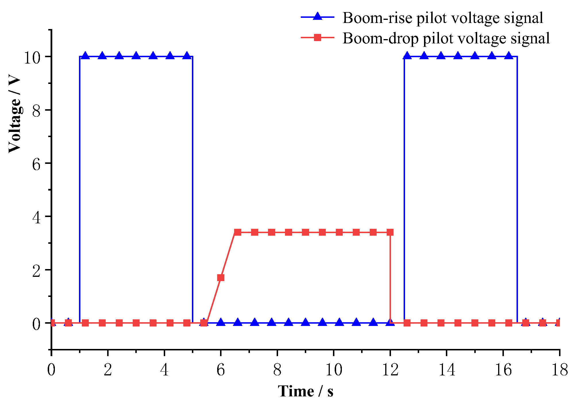
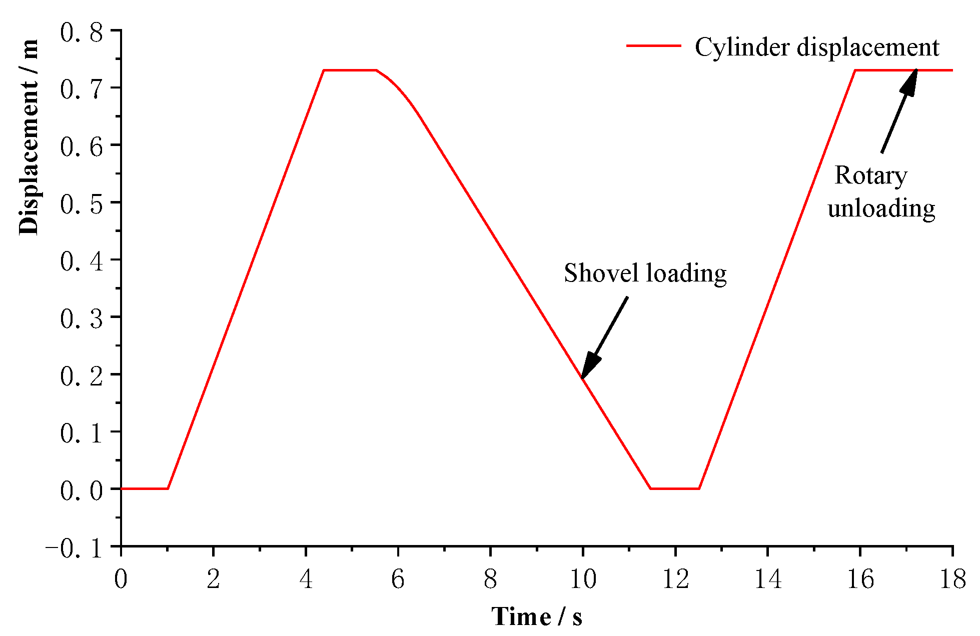
The output signal curve of the pilot handle is shown in Figure 12. The displacement curve of the actuator cylinder which is a typical movement cycle of the boom cylinder is shown in Figure 13. When the pilot signal output is 0, the motor to drive the main pump is in the idling stage and the cylinder does not move. At 1 s, the given boom-rise pilot output signal is 10 V. The boom cylinder extends at the highest speed with uniform speed. At 5.5 s, the boom-drop pilot output signal is linear to increase, and becomes constant at 6.5 s. The boom cylinder decreases at an accelerated speed first, and then decreases at a uniform speed. During the descent process, the shoveling and digging loading action is performed. After the shoveling action is executed, the boom cylinder is extended again. After the cylinder is fully extended, the slewing mechanism performed the revolving action and unloaded at the designated position.
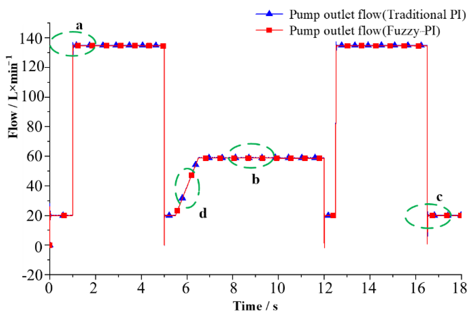
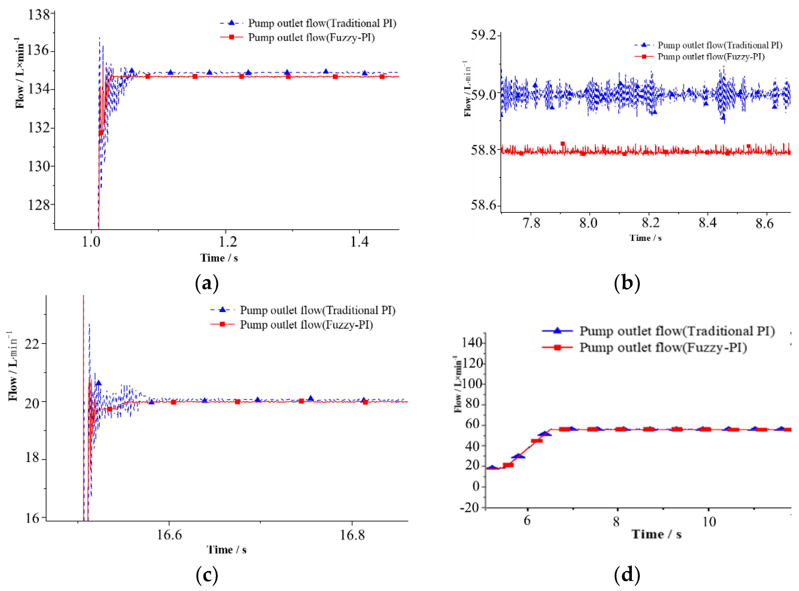
Figure 14 shows the comparison curves of pump outlet flow and Figure 15 is the partial magnification curve of pump outlet flow. It can be seen that whether it is a step rise, a step drop or a ramp in the flow rate, the overshoot and responsiveness of the pump outlet flow under the fuzzy PI control are significantly better than that of the traditional PI control. When the signal is a ramp signal, the two control methods can effectively follow the target control signal and the flow fluctuation in the response process is smaller. When the system enters a stable state, the pump outlet flow pulsation under the fuzzy PI control is smaller. When fuzzy PI control is used, the pump outlet flow overshoot is smaller, the response is faster, and the stability is better.
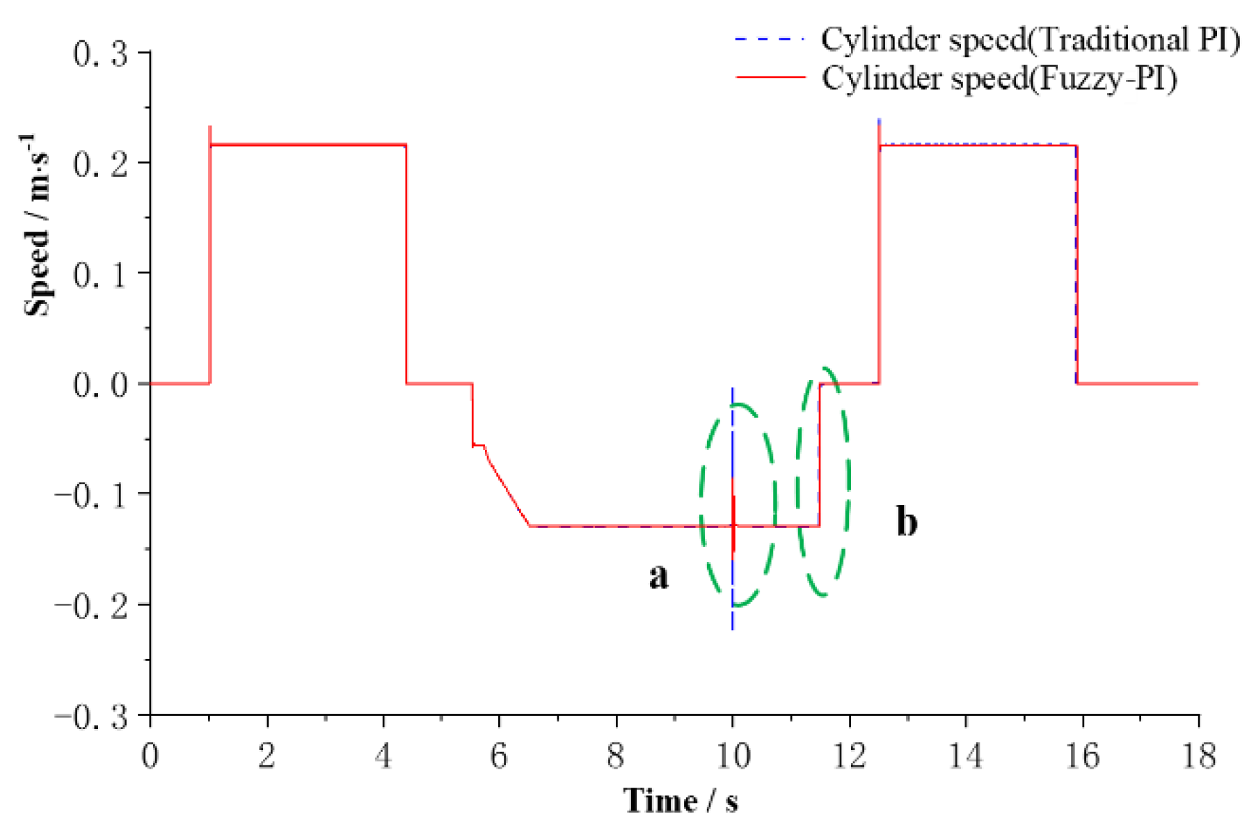
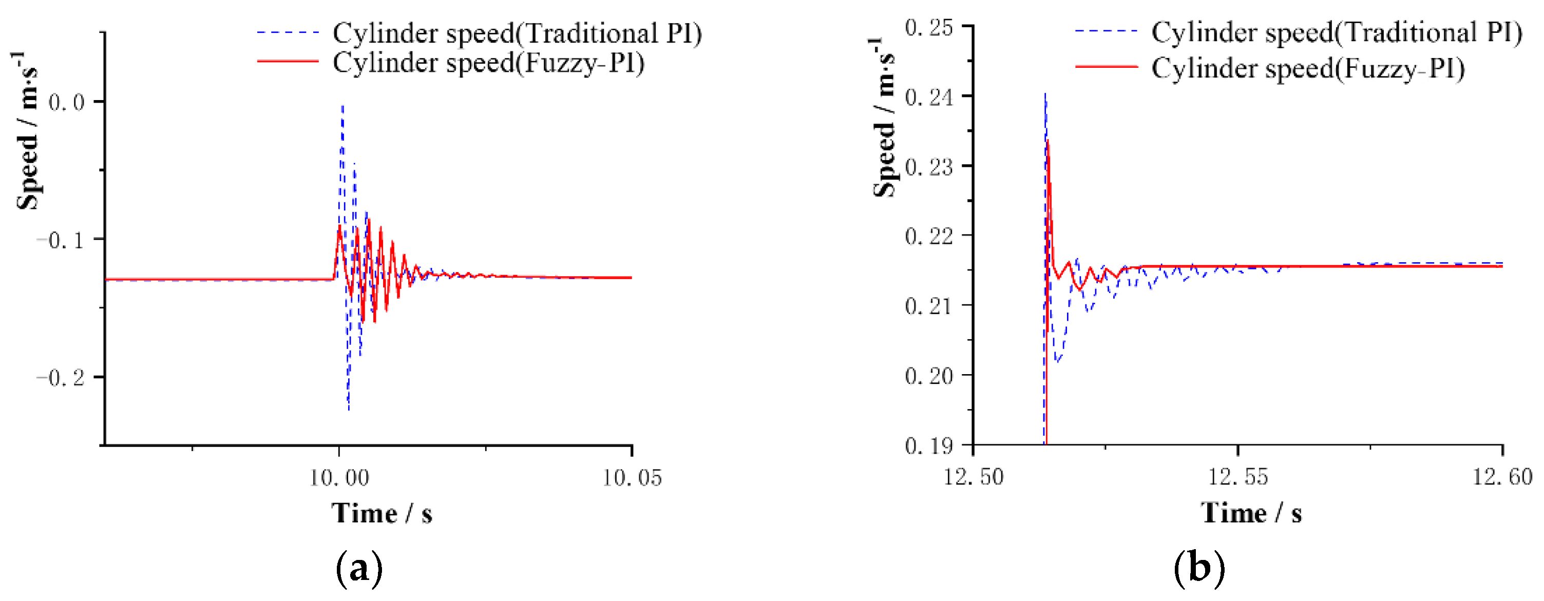
Figure 16 is the cylinder speed curves and Figure 17 is the partial amplification curve of the cylinder speed. It can be seen from the partial amplification curve of the cylinder speed during shoveling that when the load is loaded during work, the cylinder speed fluctuates greatly, with large spikes and obvious jitter under the traditional PI control. While, under fuzzy PI control, the cylinder speed only fluctuates slightly, and the adjustment time is shorter. When the speed of the cylinder changes step by step, the cylinder speed has a large overshoot, the adjustment time is longer and the oscillation is obvious under the traditional PI control. While under the fuzzy PI control, cylinder speed is less overshoot, the adjustment time is shorter, and there is only a small oscillation. Therefore, when fuzzy PI control is used, the cylinder speed operation has better robustness and stability.
From the simulation analysis, when the fuzzy PI control system is employed, the outlet flow impact of the hydraulic pump and the pulsation are smaller. The responsiveness and robustness are better than that of traditional PI control.

5. Experimental Study

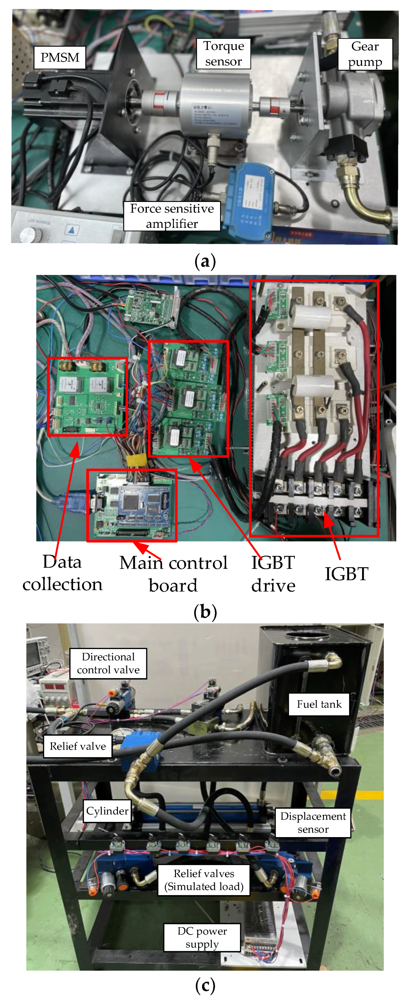
Experimental research were carried out further. A positive flow system test rig which matches the test motor power was built. The schematic diagram of the positive flow system test rig is shown in Figure 18 and the test rig layout is shown in Figure 19.
The test rig consists of a power source and the hydraulic system. The power source mainly includes a motor controller, a PMSM, a torque sensor, and a gear pump. The hydraulic system mainly includes a cylinder, a displacement sensor, a pressure sensor, a directional control valve, and two proportional relief valves. The proportional relief valve is used to simulate load. The positive hydraulic system is realized by adjusting the electric motor speed.
The employed PMSM parameters are shown in Table 3.
The parameters of the hydraulic pump and the cylinder of the test rig are shown in Table 4 and Table 5.

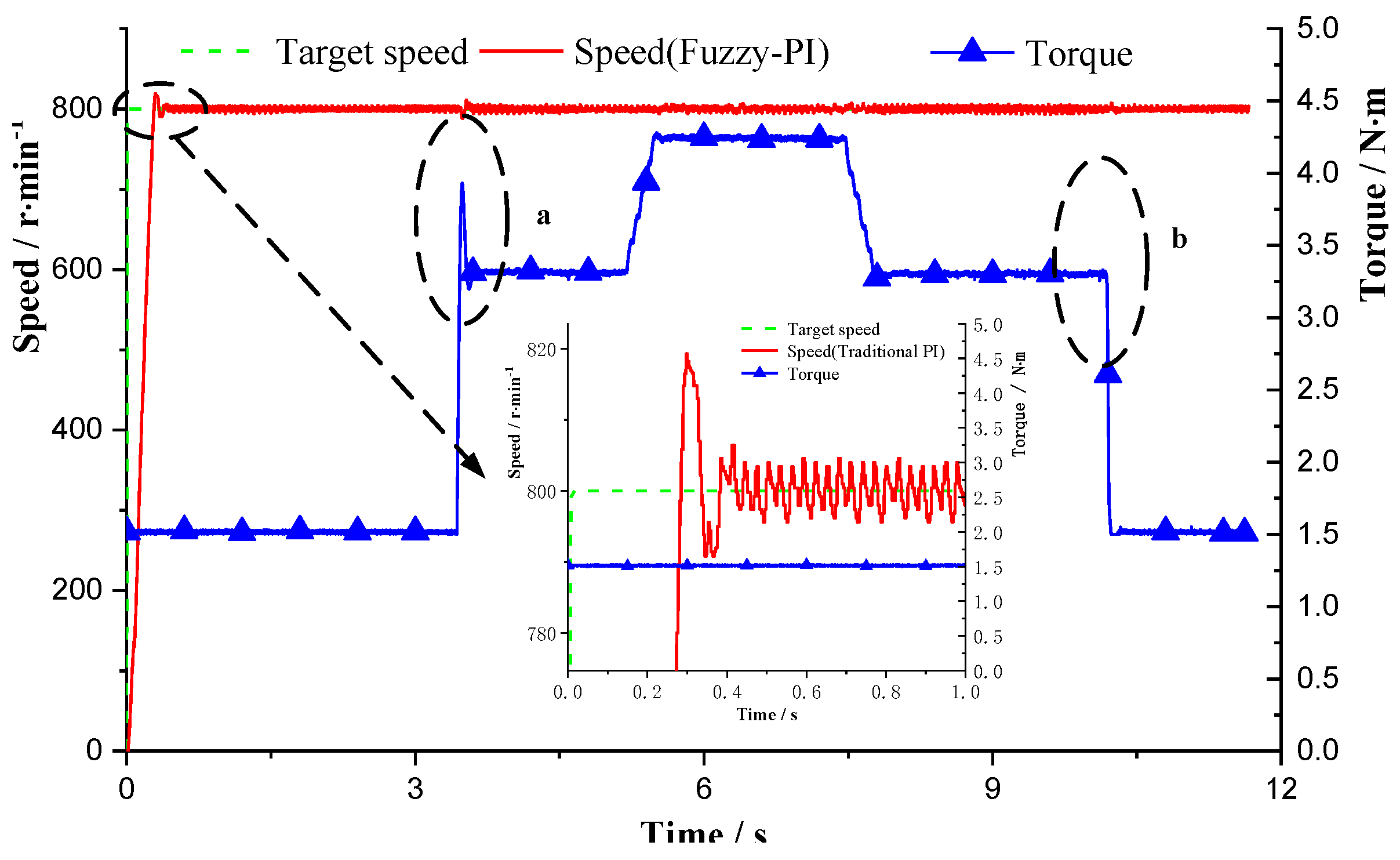
5.1. Comparative Test Research on No-Load Variable Speed

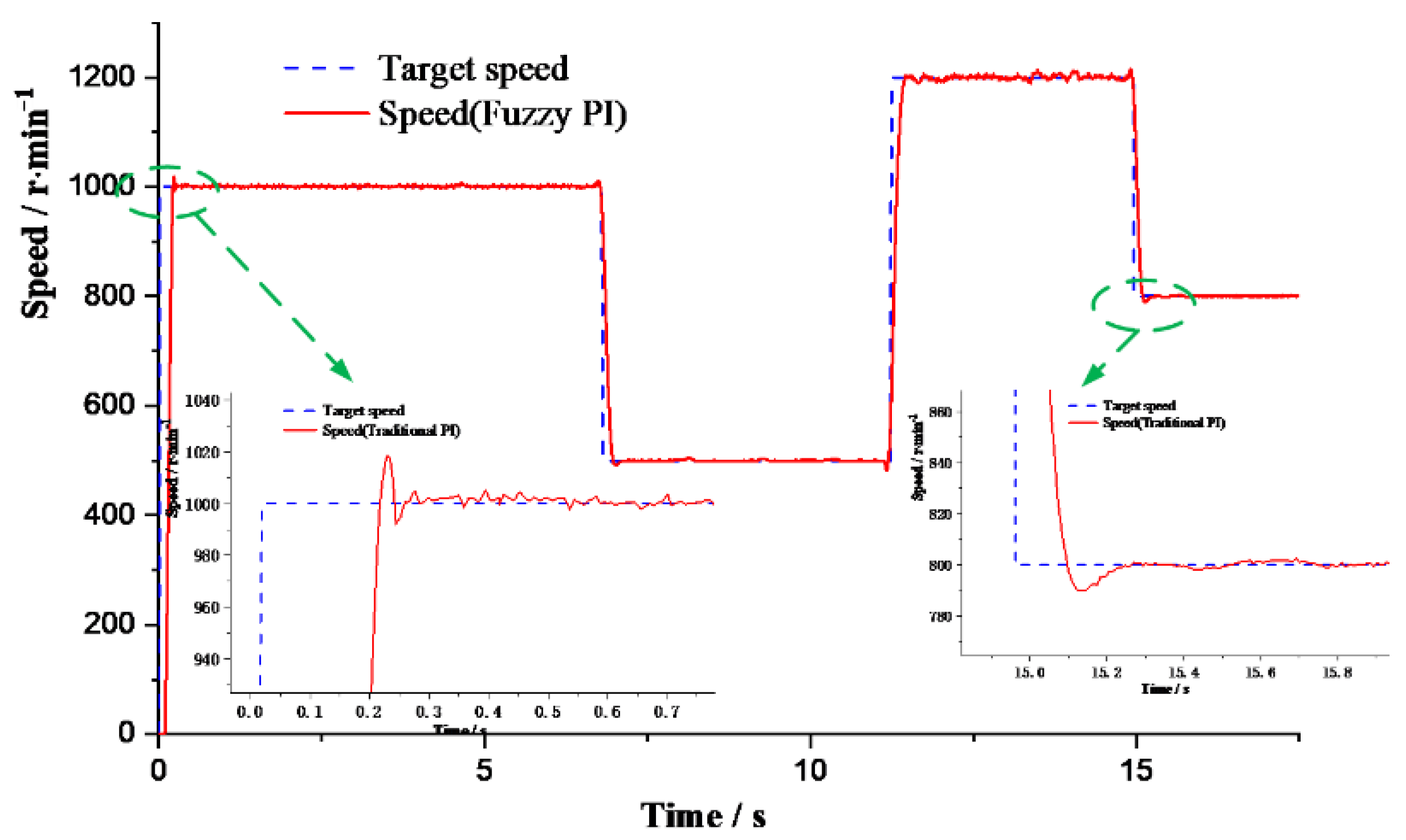
The speed curves of the motor control system under the no-load variable speed based on traditional PI and fuzzy PI when a step signal is input are provided in Figure 20 and Figure 21, respectively. The target speed change process is 1000-500-1200-800 (r/min). The two fragments of speed with the mutation from 0 to 1000 r/min and the mutation from 1200 to 800 r/min are studied for comparison. When the electric motor speed changes from 0 to 1000 r/min, the overshoot of the PI control and fuzzy PI control are 40 r/min and 20 r/min, respectively. Moreover, the times to steady state are 600 ms and 420 ms, respectively. When the electric motor speed changes from 1200 to 800 r/min, the overshoot of the PI control and fuzzy PI control are 35 r/min and 10 r/min, respectively. Moreover, the times to steady state are 350 ms and 260 ms, respectively. When the electric motor control system enters a steady state, the speed fluctuation of the PI control and fuzzy PI control are about 1.5/100 and 1/100, respectively. It can be seen that under the same operating conditions, the electric motor speed response and the overshoot are faster with fuzzy PI control. At the same time, the speed fluctuation is also significantly smaller after entering the steady state.
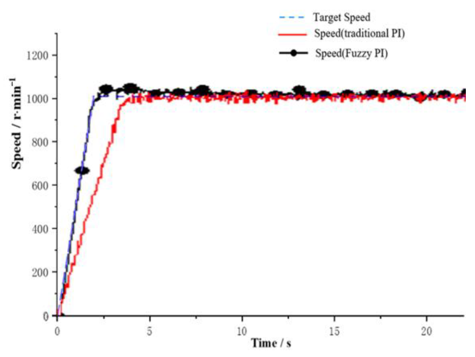
The speed curves of the motor control system under the no-load variable speed based on traditional PI and fuzzy PI when a ramp signal is input are provided in Figure 22. It can be seen that two control methods can follow the target ramp input well. Between of them, the fuzzy PI control method is more ideal, although there is some overshoot. The traditional PI has a slow following response.

5.2. Comparative Test on Constant Speed Loading

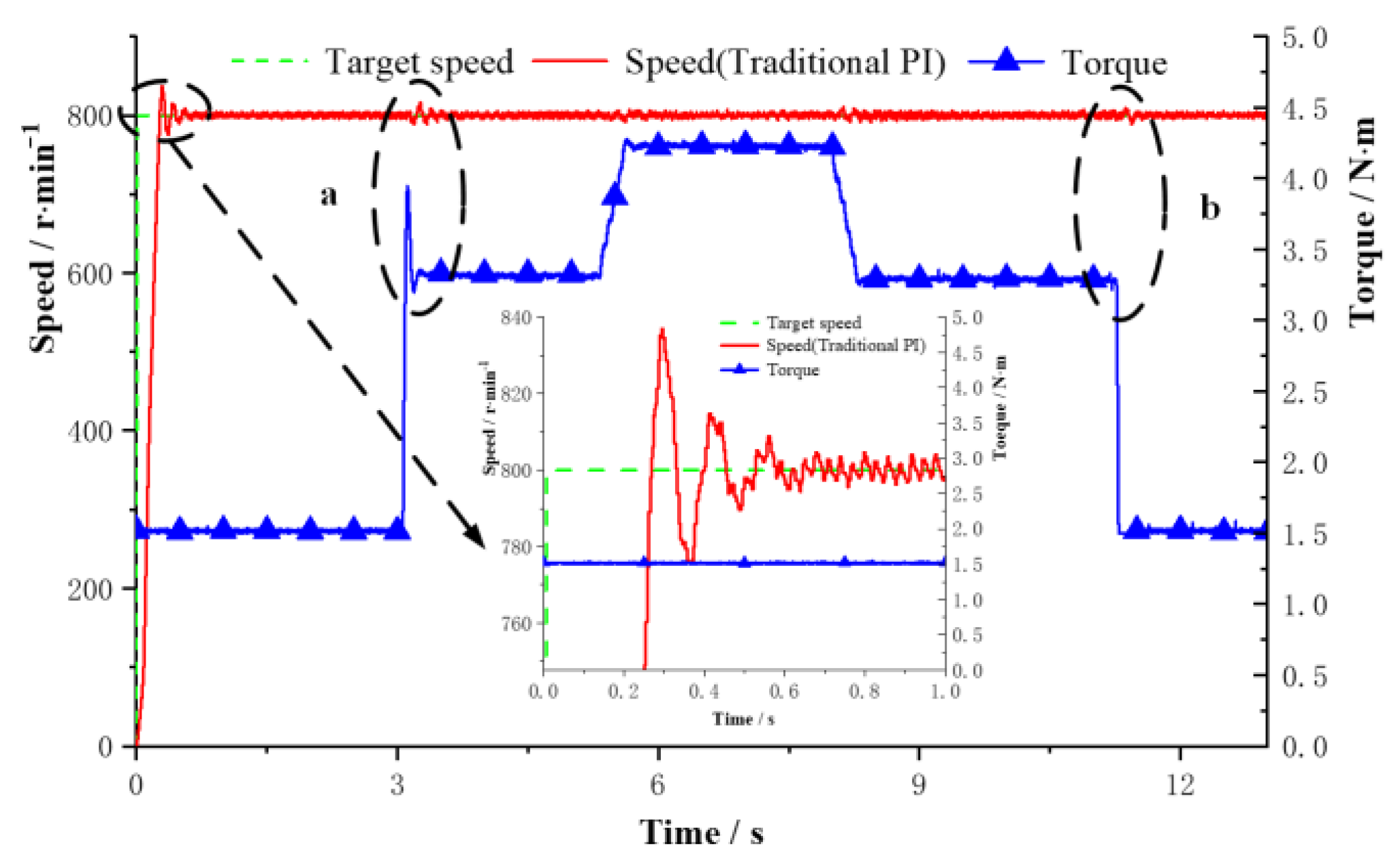
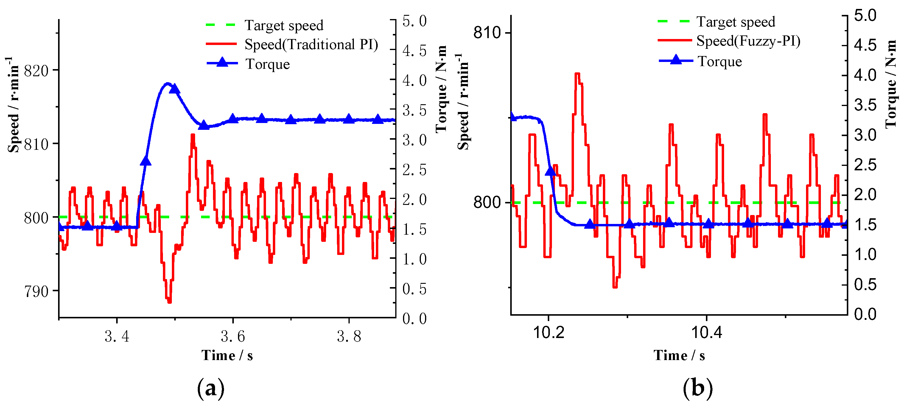
The speed curves of the motor control system under the constant speed loading based on the traditional PI control and the fuzzy PI control are provided in Figure 23, Figure 24, Figure 25 and Figure 26. The test target speed is 800 r/min, and the initial load is 1.5 N·m. When the electric motor starts, the overshoot of the PI control and fuzzy PI control are 38 r/min and 19 r/min, respectively. Moreover, the times to steady state are 600 ms and 420 ms, respectively. Under the traditional PI control, when the load is added to 3.3 N·m at 3 s, the speed jittered, and the fluctuation range is 17 r/min. Then it enters the steady state after 300 ms. Torque is released to 1.5 N·m at 11 s, and the speed jittered with a fluctuation range of 12 r/min. After 140 ms, it enters the steady state again. While under the fuzzy PI control, the load is suddenly added to 3.3 N·m at 3.4 s, and the speed fluctuation range is 12 r/min. Then it enters the steady state after 120 ms. Torque is released to 1.5 N·m at 10 s, and the speed jittered with a fluctuation range of 8 r/min. After 80 ms, it enters the steady state again. It can be seen that during the loading process, when fuzzy PI control is adopted, the speed jitter is smaller and the response is faster. Therefore, the system adopting fuzzy PI control has stronger anti-load disturbance ability, better robustness, and anti-interference performance.
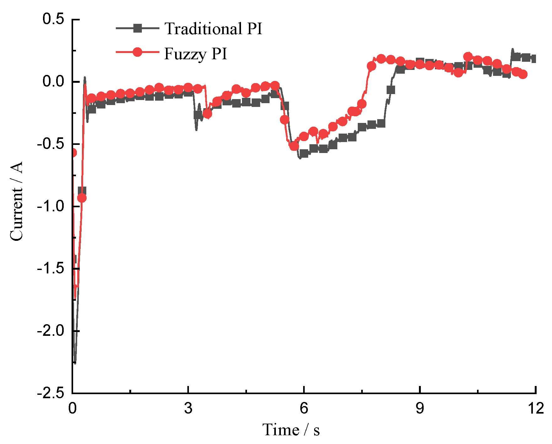
The i d and i q curves of the motor control system under the constant speed loading based on the traditional PI control and the fuzzy PI control are provided in Figure 27 and Figure 28, respectively. It can be seen that after loading, the current of quadrature axis and direct axis are smaller when the fuzzy PI control is adopted. After entering the steady state, the current fluctuation is smaller, and the current stability is also better.
It can be seen from the test results that the fuzzy PI control can make the electric motor control system not only has a faster response performance, but also has a smaller overshoot. In loading and unloading conditions, when fuzzy PI control is used, the electric motor speed fluctuation and the time to the steady state are significantly smaller.

5.3. Positive Flow System Test

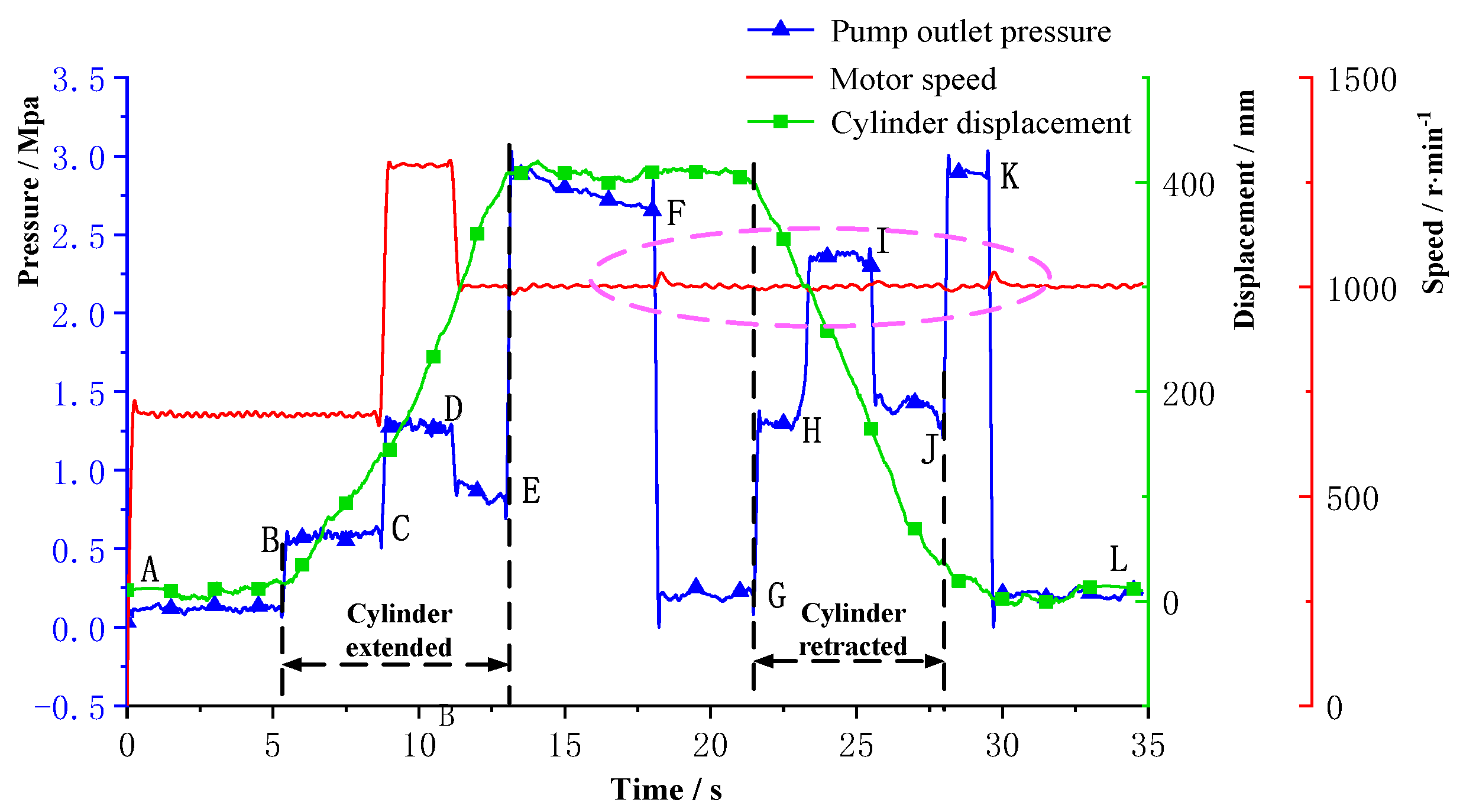
To verify the performance of the designed controller, the variable speed, constant speed, loading and unloading tests are carried out during the cylinder extension and retraction process, shown in Figure 29. The AB and JL are the static stages of the cylinder, the pump outlet pressure is about 0 MPa, and the cylinder displacement is about 0 mm. At the time of B, the directional control valve is switched to the left position, the cylinder begins to extend without load. The target speed of the BC section is 700 r/min, and the pump outlet pressure is about 0.5 MPa. At the time of C, the electric motor speed changes to 1280 r/min. At this time, the pump outlet flow becomes larger, and the operating speed of the cylinder becomes larger too. The slope of the displacement curve corresponding to the CD segment becomes larger than that of the BC segment. At the time of D, the electric motor speed changes to 1000 r/min. At the time of E, the cylinder moves to the maximum stroke, until the directional control valve is switched to the right position at time G when the cylinder starts to retract. The EF section indicates that the cylinder is at the maximum stroke, the pump outlet hydraulic oil overflows through the main relief valve to the oil tank, and the pump outlet pressure is the relief valve which pressure is 2.7 MPa. The FG section is the directional control valve working in the neutral position. Pump outlet oil directly flows back to the oil tank through the check valve, and the pressure is close to 0 MPa. At the time of H, the relief valve on the side of the rodless cavity is adopted to load, the pump outlet pressure changes from 1.4 MPa to 2.4 MPa. At the time of I, the relief valve is unloaded, the cylinder is retracted without load, and the pump outlet pressure returns to 1.4 MPa. At the time of J, the cylinder is retracted to the minimum stroke, the pump outlet oil overflows from the main relief valve back to the tank. At this time the pump outlet pressure is the relief valve pressure which is 2.7 MPa.
Seen from Figure 29, when the motor speed changes, the slope of the cylinder displacement curve changes accordingly, and the responsiveness and following performance are superior. When the electric motor speed is constant, the displacement curve is stable, and the slope is consistent. The cylinder runs smoothly with no pressure shock.
A partial enlarged curve diagram of the loading and unloading process is provided in Figure 30. When the load fluctuates, the electric motor speed fluctuates to a certain extent. When loading and unloading, the load power is about 50% of the motor power, and the electric motor speed fluctuates within 1% of the target value. At the time of F and K when the pressure changes, the load power is about 70% of the motor power, and the electric motor speed fluctuates within 3.5% of the target value. When the load is stable, the electric motor speed is relatively stable, and the steady-state error is about 0.3%.
According to test results of the positive flow system, when the vector control system based on fuzzy PI is used, not only the motor has good responsiveness, stable rotation speed, and good load disturbance resistance, but also the pressure shock caused by the hydraulic system can be reduced. When the load fluctuates severely, the electric motor speed fluctuation is small, the stability is fine, and the system has better maneuverability. The test results show that the vector control system based on fuzzy PI has better responsiveness, stability, and anti-load disturbance ability. It can better apply to electric CM under severe load fluctuations.

6. Conclusions

Aiming at the fact that the existing motor control system is not suitable for the working conditions of electric CM, a vector control strategy based on fuzzy PI of the PMSM is proposed and used in a positive flow system of a CM. Its feasibility was verified through simulation and test. The main conclusions are as follows:
  • Compared with the traditional PI control, when using the fuzzy PI control, the motor speed output overshoot is smaller, the response is faster, the load disturbance has less affection, and the stability is higher;
  • When the fuzzy PI control is used, the electric motor output torque overshoot is slightly increased, but the responsiveness and stability are significantly improved;
  • The simulation results show that when the load is variable, the fluctuation of motor speed was approximately 1.5% with fuzzy PI, and 2.5% with traditional PI;
  • The test results show that when the load fluctuates drastically, the electric motor speed fluctuation is within 3.5%, and the steady-state error is only approximately 0.3%.
CM has the characteristics of severe load fluctuation, so it is necessary to avoid the interference of fluctuation to CM mobility. The vector control system of permanent magnet synchronous motor based on fuzzy PI proposed in this paper is suitable for electric CM with large load fluctuation and complex working conditions. In the next step of work, it will be tested on the actual excavator under the actual working conditions to verify its responsiveness, stability, and anti-interference ability. In addition, the calculation burden caused by the fuzzy control algorithm will be studied in depth.

Author Contributions

Conceptualization, Z.L. and T.L.; methodology and software, Y.Z.; formal analysis, Q.C. and W.G.; investigation, S.F. and Y.Z.; writing—original draft preparation, Q.C. and H.R. All authors have read and agreed to the published version of the manuscript.

Funding

This work was supported by National Natural Science Foundation of China (Grant No. 51875218 and 52175051), key projects of natural science foundation of Fujian Province (Grant No. 2021J02013), Collaborative Innovation Platform of Fuzhou-Xiamen-Quanzhou Independent Innovation Demonstration Area (Grant No. 3502ZCQXT202002), Fujian University industry university research joint innovation project plan (Grant No. 2022H6007), and Shanghai Municipal Administration for Market Regulation (Grant No. 2021-26).

Institutional Review Board Statement

Not applicable.

Informed Consent Statement

Not applicable.

Conflicts of Interest

The authors declare no conflict of interest.

References

  1. Lin, T.; Lin, Y.; Ren, H.; Chen, H.; Chen, Q.; Li, Z. Development and key technologies of pure electric construction machinery. Renew. Sustain. Energy Rev. 2020, 132, 110080. [Google Scholar] [CrossRef]
  2. Ge, L.; Quan, L.; Zhang, X.; Dong, Z.; Yang, J. Power matching and energy efficiency improvement of hydraulic excavator driven with speed and displacement variable power source. Chin. J. Mech. Eng. 2019, 32, 100. [Google Scholar] [CrossRef] [Green Version]
  3. Lin, T.; Lin, Y.; Ren, H.; Chen, H.; Li, Z.; Chen, Q. A double variable control load sensing system for electric hydraulic excavator. Energy 2021, 223, 119999. [Google Scholar] [CrossRef]
  4. Chen, Q.; Cai, S.; Li, X.; Lin, T. Power train system control of electric loader based on positive flow system. Appl. Sci. 2022, 12, 12. [Google Scholar] [CrossRef]
  5. Homaeinezhad, M.R.; Farzannasab, M. Switching position-torque control system for increasing servo PMDC positioning precision in presence of intense external disturbance loading. Mech. Syst. Signal Processing 2021, 158, 107816. [Google Scholar] [CrossRef]
  6. Zhang, F.; Peng, T.; Dan, H.; Lin, J.; Su, M. Modulated model predictive control of permanent magnet synchronous motor. In Proceedings of the 2018 IEEE International Conference on Industrial Electronics for Sustainable Energy Systems (IESES), Hamilton, New Zealand, 31 January–2 February 2018. [Google Scholar]
  7. Luo, S.; Cheng, M.; Ding, R.; Wang, F.; Xu, B.; Chen, B. Human–Robot Shared Control Based on Locally Weighted Intent Prediction for a Teleoperated Hydraulic Manipulator System. IEEE/ASME Trans. Mechatron. 2022, 1–13. [Google Scholar] [CrossRef]
  8. Chen, Q.; Lin, T.; Ren, H. Parameters optimization and control strategy of power train systems in hybrid hydraulic excavators. Mechatronics 2018, 56, 16–25. [Google Scholar] [CrossRef]
  9. Shen, W.; Zhao, H. Fault tolerant control of nonlinear hydraulic systems with prescribed performance con-straint. ISA Trans. 2022, in press. [CrossRef]
  10. Casadei, D.; Serra, G.; Tani, A. Implementation of a Direct Torque Control Algorithm for Induction Motors Based on Discrete Space Vector Modulation. IEEE Trans. Power Electr. 2000, 15, 769. [Google Scholar] [CrossRef]
  11. Zhang, X.; Foo, G.H.B. A Constant Switching Frequency-Based Direct Torque Control Method for Interior Permanent-Magnet Synchronous Motor Drives. IEEE/ASME Trans. Mechatron. 2016, 21, 1445–1456. [Google Scholar] [CrossRef]
  12. Hu, Y.; Li, Y.; Ma, X.; Li, X.; Huang, S. Flux-Weakening Control of Dual Three-Phase PMSM Based on Vector Space Decomposition Control. IEEE Trans. Power Electr. 2021, 36, 8428–8438. [Google Scholar] [CrossRef]
  13. Holtz, J. Sensorless Control of Induction Machines—With or Without Signal Injection? IEEE Trans. Ind. Electron. 2006, 53, 7–30. [Google Scholar] [CrossRef] [Green Version]
  14. Chen, Q.; Lin, T.; Ren, H. A novel control strategy for an interior permanent magnet synchronous machine of a hybrid hydraulic excavator. IEEE Access 2017, 6, 3685–3693. [Google Scholar] [CrossRef]
  15. Chen, Q.; Lin, T.; Ren, H. Direct torque control of a permanent magnet synchronous machine for hybrid hydraulic excavator. IET Electr. Power Appl. 2019, 13, 222–228. [Google Scholar] [CrossRef]
  16. Wang, T.; Wang, Q. Optimization Design of a Permanent Magnet Synchronous Generator for a Potential Energy Recovery System. IEEE Trans. Energy Conver. 2012, 27, 856–863. [Google Scholar] [CrossRef]
  17. Hoai, H.; Chen, S.; Than, H. Realization of the Sensorless Permanent Magnet Synchronous Motor Drive Control System with an Intelligent Controller. Electronics 2020, 9, 365. [Google Scholar] [CrossRef] [Green Version]
  18. Elsonbaty, N.A.; Enany, M.A.; Hassanin, M.I. An Efficient Vector Control Policy for EV-Hybrid Excited Perma-nent-Magnet Synchronous Motor. World Electr. Veh. J. 2020, 11, 42. [Google Scholar] [CrossRef]
  19. Fu, S.; Li, Z.; Lin, T.; Chen, Q.; Ren, H. A Positive Flow Control System for Electric Excavators Based on Variable Speed Control. Appl. Sci. 2020, 10, 4826. [Google Scholar] [CrossRef]
  20. Jie, C.; Yanling, G. Research on Control Strategy of the Electric Power Steering System for All-Terrain Vehicles Based on Model Predictive Current Control. Math. Probl. Eng. 2021, 2021, 6642042. [Google Scholar] [CrossRef]
  21. Alves, A.G.P.; Rolim, L.G.B.; Dias, R.F.S.; Santos, P.T.P. VSC plug-and-play operation using online grid parameter es-timation for PI self-tuning. IET Power Electron. 2020, 13, 4359–4367. [Google Scholar] [CrossRef]
  22. Liu, J.; Zhao, M.; Li, G.; Chen, J. Multiple linear regression prediction and wavelet neural network based in-telligent online tuning control method. IEEE Access 2020, 8, 160684–160696. [Google Scholar] [CrossRef]
  23. Murali, N.; Ushakumari, S. Performance comparison between different rotor configurations of PMSM for EV application. In Proceedings of the 2020 IEEE Region 10 Conference (Tencon), Osaka, Japan, 16–19 November 2020; pp. 1334–1339. [Google Scholar]
  24. Ahmed, A.A.; Kim, J.-S.; Lee, Y.I. Model predictive torque control of PMSM for EV drives: A comparative study of finite control set and predictive dead-beat control schemes. In Proceedings of the 2016 Eighteenth International Middle East Power Systems Conference (MEPCON), Cairo, Egypt, 27–29 December 2016; pp. 156–163. [Google Scholar]
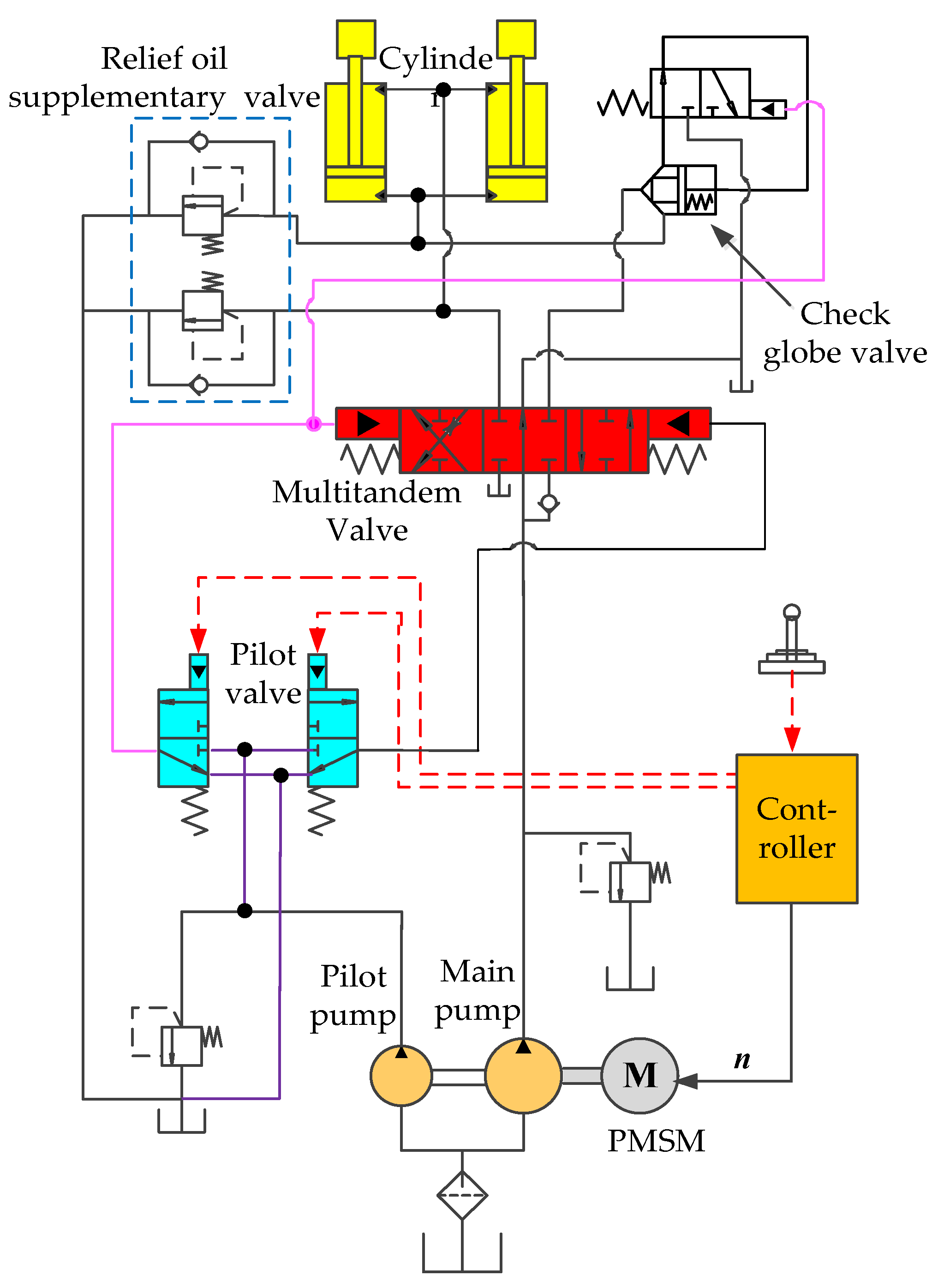
Figure 1. Simplified principle diagram of quantitative pump-variable speed positive flow system for an excavator boom.
Applsci 12 10072 g001
Figure 2. Hardware circuit structure diagram of PMSM control system.
Applsci 12 10072 g002
Figure 3. The control neural network structure diagram.
Applsci 12 10072 g003
Figure 4. The dynamic structure diagram of the vector control system of PMSM.
Applsci 12 10072 g004
Figure 5. The simplified structure of the vector control system of PMSM.
Applsci 12 10072 g005
Figure 6. The block diagram of speed loop for open-loop system.
Applsci 12 10072 g006
Figure 7. Diagram of the online tuning regulator for speed PI parameters.
Applsci 12 10072 g007
Figure 8. Vector control system-positive flow system co-simulation model.
Applsci 12 10072 g008
Figure 9. The comparison curve of speed changes.
Applsci 12 10072 g009
Figure 10. The partial enlarged view of the speed change. (a) The electric motor starts; (b) the speed changes suddenly; (c) the load is suddenly applied.
Applsci 12 10072 g010
Figure 11. The torque change view when the load was suddenly loaded.
Applsci 12 10072 g011
Figure 12. The output signal of the pilot handle.
Applsci 12 10072 g012
Figure 13. The displacement of the execute cylinder.
Applsci 12 10072 g013
Figure 14. The comparison curve of pump outlet flow.
Applsci 12 10072 g014
Figure 15. The partial magnification curve of pump outlet flow. (a) Flow step rise; (b) flow stability; (c) flow step drop; (d) flow ramp response.
Applsci 12 10072 g015
Figure 16. The cylinder speed under two control system.
Applsci 12 10072 g016
Figure 17. The partial amplification curve of the cylinder speed. (a) During shoveling loading; (b) step change.
Applsci 12 10072 g017
Figure 18. The simplified schematic diagram of positive flow system.
Applsci 12 10072 g018
Figure 19. The test rig layout of positive flow system. (a) Power source; (b) hardware of PMSM vector control system; (c) hydraulic system.
Applsci 12 10072 g019
Figure 20. Speed curve of traditional PI under no-load variable speed.
Applsci 12 10072 g020
Figure 21. Speed curve of fuzzy PI under no-load variable speed.
Applsci 12 10072 g021
Figure 22. Speed curve under no-load variable speed with a ramp signal input.
Applsci 12 10072 g022
Figure 23. Speed change curve of traditional PI under constant speed loading.
Applsci 12 10072 g023
Figure 24. Partial amplification curve of traditional PI under constant speed loading. (a) Loaded; (b) unloaded.
Applsci 12 10072 g024
Figure 25. Speed change curve of fuzzy PI under constant speed loading.
Applsci 12 10072 g025
Figure 26. Partial amplification curve of fuzzy PI under constant speed loading. (a) Loaded; (b) unloaded.
Applsci 12 10072 g026
Figure 27. Comparison curve of I d change under constant speed loading.
Applsci 12 10072 g027
Figure 28. Comparison curve of I q change under constant speed loading.
Applsci 12 10072 g028
Figure 29. The test curve of positive flow system.
Applsci 12 10072 g029
Figure 30. The partial amplification curve of positive flow system test.
Applsci 12 10072 g030
Table 1. Fuzzy control rule table of Δ K p .
eNBNMNSZOPSPMPB
ec
NBPBPBPMPMPSZOZO
NMPBPBPMPSPSZONS
NSPMPMPMPSZONSNS
ZOPMPMPSZONSNMNM
PSPSPSZONSNSNMNB
PMPSZONSNMNMNMNB
PBZOZONMNMNMNBNB
Table 2. Fuzzy control rule table of Δ K i .
eNBNMNSZOPSPMPB
ec
NBNBNBNMNMNSZOZO
NMNBNBNMNSNSZOZO
NSNBNMNSNSZOPSPS
ZONMNMNSZOPSPMPM
PSNMNSZOPSPSPMPB
PMZOZOPSPSPMPBPB
PBZOZOPSPMPMPBPB
Table 3. Parameters of electric motor.
Rate Power/WRate Speed/rpmRate Torque/N·mRate Current/APole-Pairs
750180064.24
Table 4. Parameters of gear pump.
Nominal
Displacement/
mL·r−1
Pressure
/MPa
Speed
/r·min−1
WorkingMaxRatedMaxMin
10202218003000500
Table 5. Parameters of executive cylinder.
Cylinder Diameter/mmPiston Rod Diameter/mmCylinder Stroke/mm
6325400
Publisher’s Note: MDPI stays neutral with regard to jurisdictional claims in published maps and institutional affiliations.