Article

Investigation into the Modulation Characteristics of Motor Current Signals in a Belt Transmission System for Machining Monitoring

1
School of Industrial Automation, Beijing Institute of Technology, Zhuhai 519088, China
2
College of Intelligence Science and Technology, National University of Defence Technology, Changsha 410073, China
3
Centre for Efficiency and Performance Engineering, University of Huddersfield, Huddersfield HD1 3DH, UK
*
Authors to whom correspondence should be addressed.
Appl. Sci. 2022, 12(19), 10088; https://doi.org/10.3390/app121910088
Submission received: 8 September 2022 / Revised: 29 September 2022 / Accepted: 4 October 2022 / Published: 7 October 2022

Abstract

:
Belt transmission is one of the most common forms of transmission on CNC lathes. To assess the impact of belt performance on monitoring machining conditions using motor current signal analysis, we developed a dynamic model for belt-driven electromechanical spindle systems. This model enables the coupling of multi-physics variables including mechanical dynamics, particularly the dynamic axil and belt bending motions of belt transmissions and electromagnetic effects. Thus, various changes in belt transmission, including different degrees of belt tension and defects with inherent motor and spindle errors, can be investigated. The modulation characteristics of the current and speed signals revealed that belt transmission can cause a high degree of modulation, reflected by the rich harmonic sidebands at the belt-passing frequency in the motor current spectrum. The rate and extent of belt wear worsened with excessive wear and inadequate tension. It was confirmed that the sideband at the spindle rotating frequency was slightly impacted by changes in the belt conditions. This model was verified based on a CNC lathe induced with different degrees of belt looseness. These conclusions drawn from the numerical analyses can be used for motor current signal analysis, providing reliable and accurate results for machining monitoring.

1. Introduction

Monitoring machining processes is a common practice to ensure workpiece quality, system reliability, and manufacturing automation. The complexity of the process, as well as the changing cutting conditions, makes monitoring the machining process difficult. In contrast to conventional vibration [1], acoustic [2], and torque [3] monitoring techniques, motor current signature analysis (MCSA) for monitoring machining conditions offers advantages such as easy access, low transducer cost, non-interference with machining processes, and suitability for noisy factory environments [4]. Owing to these advantages, numerous studies have used MCSA to monitor cutting forces, tool wear, tool breakage detection, workpiece chatter, and other aspects of machining [5,6,7,8].
Dynamic loads are inevitable in machining and are also applied to spindle motors during machine tool operation, in addition to static loads. As shown in Figure 1, several nonlinear vibrations cause torque and speed fluctuations during machining, which alters the motor’s flux behaviours. This results in a change in the frequency modulation of the stator current. Thus, motor current signal analysis is mainly based on the frequency characteristics caused by changes in the machining conditions. To extract signal characteristics and represent the operating state of a lathe, Liu et al. [9] applied wavelet transformation and FFT to the total current load signal of the lathe. According to Kuntolu et al. [10], the current signal can effectively predict the wear of machining tools. As demonstrated by Stavropoulos et al. [11], the relationship between the current signal and tool wear is less affected by environmental noise than that between tool wear and acceleration indices. To monitor machining conditions, Zou et al. [12] used the modulation signal bispectrum (MSB) method to extract the frequency amplitude and phase of interest as eigenvalues corresponding to tool wear and machining parameters.
When using MCSA methods to monitor machining conditions, the crucial challenge lies in developing signal processing methods that can accurately extract weak state features contaminated by noise. With regard to signal processing, scholars have explored various methods for identifying and tracking specific component properties, such as the Fourier transform, wavelet transform, and empirical modal decomposition. Power transmission systems for machine tools consist of motors, pulleys, belts, gearboxes, and spindles. However, it is important to note that MCSA techniques are limited by the noise introduced by long power drive paths, which causes the currents to be distorted by the transmission system.
Belt transmission systems are commonly used as an effective power transmission method for transferring motion between the remote axes on CNC machines [13]. Through the belt, the motor transmits power to the lathe spindle, providing advantages such as easy maintenance and flexible arrangement [14,15]. With the advent of high-speed drive systems for machine tools, belt drives inevitably introduce unnecessary nonlinear vibrations, such as transverse, longitudinal, and rotational vibrations under high dynamic loads (as shown in Figure 2), resulting in inaccurate monitoring of the machining conditions.
Thus far, significant research has been devoted toward belt transmission vibrations [16]. Benching et al. [17] established a mathematical model for the transverse vibration characteristics of machine tool belt drives and simulated the transverse vibration characteristics of belt drives. Incerti et al. [18] proposed a completed electromechanical system model for analysing the belt drive start-up dynamics of a DC motor-driven belt drive. Kang et al. [19] proposed a stator-based current analysis for the electrical monitoring of mechanical faults in a reduction belt–pulley coupling. Most researchers have focused on dynamic vibrations under a single excitation; however, practical applications often involve multiple excitations occurring simultaneously [14,20,21]. Ding Hu et al. [22] investigated the clutch coupling vibration of a belt–pulley system under multiple excitation sources, but the analysis was performed for a transmission ratio of 1 and neglected the electromagnetic effects. As belt drives are subject to multiple excitation sources, the current analysis of nonlinear vibrations does not consider the coupling between them [23,24,25]. Additionally, no relevant literature was found to clarify how the coupled modulation of the frequency amplitude affects the condition monitoring results when the belt is worn or improperly tensioned.
Therefore, an electromechanical coupling model with integrated parameters of the belt transmission is necessary to study the behaviour of the current modulated signal for machining condition monitoring. An analysis of the motor’s current and speed modulation must be performed under various conditions associated with belt transmission, considering both the inappropriate deformation of the belt and pulley and the motor’s electromagnetic characteristics. Accordingly, in this study, we developed a comprehensive model of a belt-driven electromechanical spindle system, in which the equations of motion associated with the mechanical components (belt drive) were solved in conjunction with the equations of the electromechanical response. By applying the Galerkin truncation method to the analytical solution of the differential equations of motion, we examined the modulation of the motor current and speed under the vibrations of the belt and pulley.
The remainder of this paper is organised as follows: Section 2 presents the model of a belt-driven electromechanical spindle system, along with the formulation and solution of the equations via the Galerkin truncation method; Section 3 discusses the examination of the modulation of current and speed signals in a belt drive system with multiple excitation sources, using the developed model. To assess the validity of the developed model, an experimental test system was developed based on a CNC lathe. Lastly, the conclusions are summarised in Section 4.

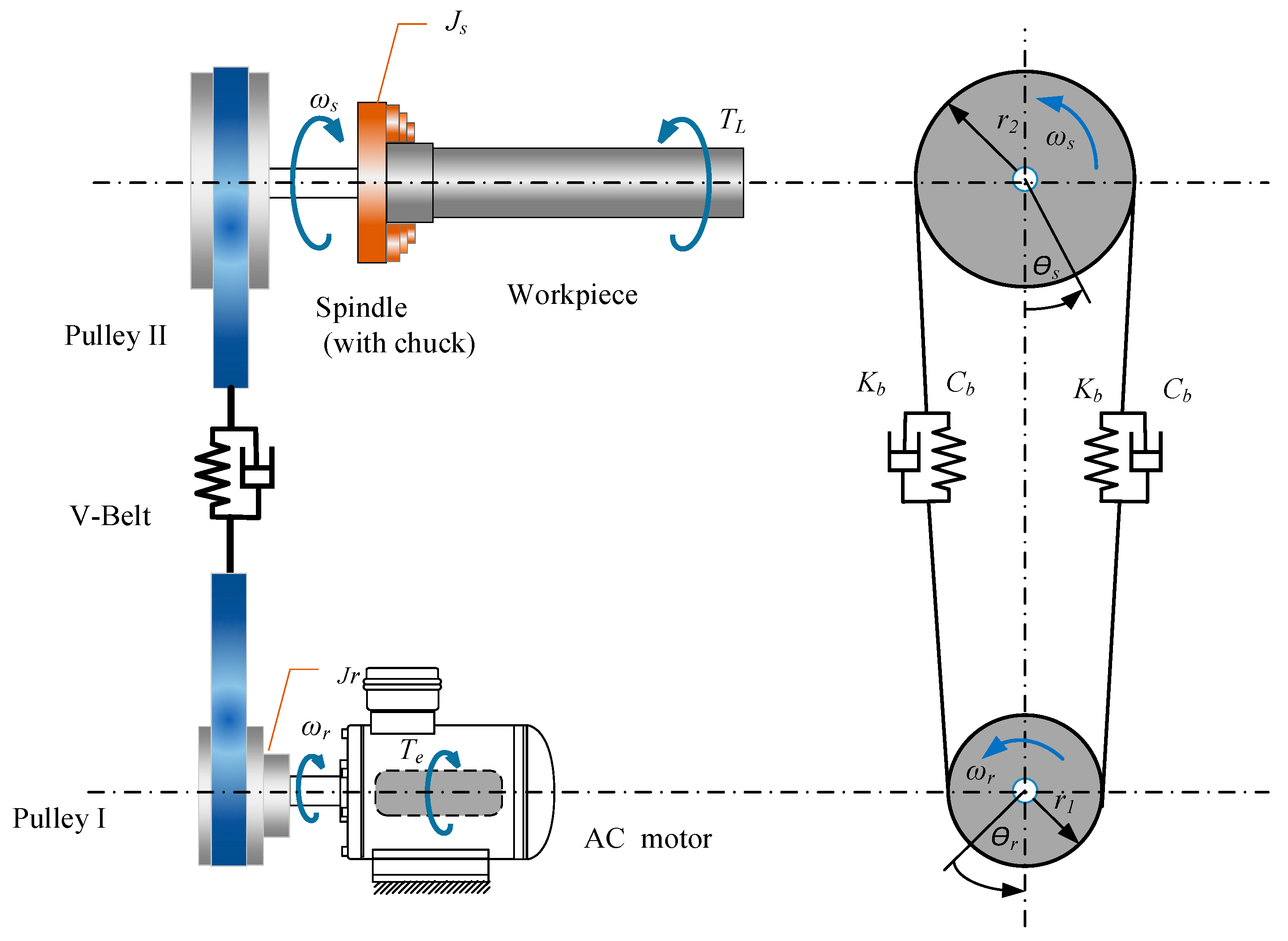
2. Dynamic Model of Belt-Driven Electromechanical Spindle System

2.1. System Modelling

Lumped parameter models are used to evaluate the belt transmission performance. This method simplifies the mathematical model. Previous studies [12,26,27,28] have established simplified dynamic models of turning processes. For the study to be accurate, both the belt deformation and motor electromagnetic characteristics must be considered. Hence, in this paper, we present a complete electromechanical system model, in which the equations of motion associated with the mechanical components (pulleys, belt transmission, and spindle) are coupled and solved along with the equations that describe the electromechanical responses.
Figure 3 shows the transmission system of a CNC lathe, which includes an industrial motor (IM), a driver pulley, a V-belt, a driven pulley, and a spindle. The workpieces were mounted on the spindle with a three-jaw calliper and turned through the cutting tool. r 1 is the driving pulley radius, θ r is the radius and angular displacement of the motor shaft, r 2 is the driven pulley radius, and θ r represents the radius and angular displacement of the main shaft. J m represents the driven pulley and spindle moments of inertia, and J s represents the driven pulley and motor moments of inertia. The belt branch was represented by the Kelvin model of a linear spring in parallel with a viscous damper. The stiffness K b of the belt branches can be determined by the well-known relationship k b = E A / l , where E is the Young’s modulus of the belt material, A is the cross-sectional area of the belt branch, l is its length, and c b is the belt–pulley damping coefficient.
The first step is to establish a mathematical IM model. According to Kirchhoff’s voltage law, IM’s stator voltage equation for the IM is [29]
V = I R + d d t ( L I ) = I R + I d L d t + L d I d t ,
where voltage V and current I are the vector matrices. L is the inductance matrix, and R is the motor resistance matrix. Following Equation (1), the healthy motor’s current differential equation is as follows:
I ˙ = [ V I ( R + ω e d d θ r ( L ( θ r ) ) ) ] L ( θ r ) 1 ,
where ω e is the electrical angular speed of the motor, and ω e = p θ r ˙ . p represent pole pairs of induction machines. The dots above current I represent time derivatives.
The electromagnetic torque T e can be calculated for the motor [30] as
T e = P 2 [ I ] T L ( θ r ) θ r [ I ]
For the driven pulley, spindle, driving pulley, and motor, the equations of the rotating motions that link these components can be easily developed, as follows:
{ J r θ r ¨ = T e T s k 1 T s c 1 J s θ s ¨ = T s k 2 + T s c 2 T L ,
where T s c 1   and   T s c 2 are the sticky moments of the belt at the driver and drive and are given by Equations (5) and (6), respectively. The stiffness moment of the belt at driver T s k 1 and the stiffness moment of the belt at driven T s k 2 are given in Equations (7) and (8), respectively.
T s c 1 = 2 c b ( r 1 θ ˙ r r 2 θ ˙ s ) r 1
T s c 2 = 2 c b ( r 1 θ ˙ r r 2 θ ˙ s ) r 2
T s k 1 = 2 k b ( P 1 P 2 ) r 1
T s k 2 = 2 k b ( P 1 P 2 ) r 2 ,
where P 1 and P 2 represent the axial tension above and below belt span L 1 , respectively.
For the machining process, T L consists of static T L 0 and dynamic component T L s cos θ s ˙ t .
T L = T L 0 + T L s cos θ s ˙ t
For brevity, the dynamic components consider only the first order owing to any effectivity and machining dynamic effects occurring on the spindle shaft. Substituting Equations (5) and (9) into Equation (4) yields
{ J r θ r ¨ = T e 2 [ k b ( P 1 P 2 ) r 1 + C b ( r 1 θ r ˙ r 2 θ s ˙ ) ] r 1 J s θ s ¨ = 2 [ k b ( P 1 P 2 ) + C b ( r 1 θ r ˙ r 2 θ s ˙ ) ] r 2 ( T L 0 + T L s cos θ s ˙ t )
In Equation (10), the belt tension forces P 1 and P 2 are calculated by establishing a belt transmission model, as discussed in the following sections.

2.2. Model of Belt Transmission

Figure 4 shows a typical belt transmission system. To consider the effect of belt transverse vibration on the rotating motion of the belly, the belt was modelled as a translating string. This implies that, assuming a quasi-static stretch belt tension P 1 , P 2 can be calculated by adopting both static and dynamic contributions as follows:
P 1 = P 0 + E A u 1 , x 1 + 1 2 0 l w 1 , x 1 2 d x 1 P 2 = P 0 + E A u 2 , x 2 + 1 2 0 l w 2 , x 2 2 d x 2
In Equation (11), the static axial tension P 0 is assumed to remain constant for the translating belt. The second term is for the dynamic component due to belt transverse motions, and the comma preceding x or t refers to the partial differentiation from x or t with respect to the previous one. x 1 and x 2 represent the neutral-axis coordinates. t denotes the time. Transverse displacements w 1 ( x 1 , t ) and w 2 ( x 2 , t ) refer to the above and below belt spans, respectively, and longitudinal displacements u 1 ( x 1 , t ) and u 2 ( x 2 , t ) refer to the above and below belt spans, respectively. With the boundary conditions of the system,
u 1 ( 0 , t ) = r 1 θ r , u 1 ( l , t ) = r 2 θ 2 u 2 ( 0 , t ) = r 2 θ s , u 2 ( l , t ) = r 1 θ r w 1 ( 0 , t ) = 0 , w 1 ( l , t ) = 0 w 2 ( 0 , t ) = 0 , w 2 ( l , t ) = 0 w 1 ,   x 1 x 1 ( 0 , t ) = w 1 ,   x 1 x 1 ( l , t ) = 1 / r 1 w 2 ,   x 2 x 2 ( 0 , t ) = w 2 ,   x 2 x 2 ( l , t ) = 1 / r 2
Substituting Equation (11) into Equation (10) leads to the following equation:
P 1 = P 0 + k b r 1 θ r r 2 θ s + 1 2 k b 0 l w 1 , x 1 2 d x 1 P 2 = P 0 + k b r 2 θ s r 1 θ r + 1 2 k b 0 l w 2 , x 2 2 d x 2
The viscoelastic belt dynamic equation is derived using Newton’s second law:
{ ρ A w 1 , t t + 2 ρ A v w 1 , x 1 t + ρ A v 2 w 1 , x 1 x 1 + c S A w 1 , t P 1 w 1 , x 1 x 1 = 0 ρ A w 2 , t t + 2 ρ A v w 2 , x 2 t + ρ A v 2 w 2 , x 2 x 2 + c S A w 2 , t P 2 w 2 , x 2 x 2 = 0 ,
where ρ is the belt density. For the transverse vibration of the translating belt, c S is the viscous damping coefficient. The motion equation defines a nonlinear piecewise mixed discrete–continuous gyro system. Numerical solutions are considered in this study because it is impossible to solve Equation (14) analytically, especially when it includes various dynamic effects such as load oscillations and eccentricities.

2.3. Galerkin Truncation Solutions

The Galerkin truncation method is well known for its ability to handle continuous nonlinear vibrations [7]. Compared to the finite element technique utilising local basis functions, the Galerkin discretisation technique provides a more accurate discretisation of a multi-degree-of-freedom system.
The equations are discretised using the Galerkin method, and the space–time coordinates are decoupled to obtain a general ordinary differential equation that is easy to calculate. The solution w ( x , t ) can be expressed by the time function q k ( t ) and the main mode function sin ( k π x ) of the transverse motion, where k is the truncated order of the belt, k = 1,2,3,4. The vibration displacement can be assumed as follows:
w ( x , t ) = k = 1 4 q k ( t ) sin ( k π x )
The substitution of Equation (15) into Equation (13) leads to
{ P 1 = P 0 + k b ( r 1 θ r r 2 θ s ) + π 2 k b 4 ( q 1 2 + 4 q 2 2 + 9 q 3 2 + 16 q 4 2 ) P 2 = P 0 + k b ( r 2 θ s r 1 θ r ) + π 2 k b 4 ( q 5 2 + 4 q 6 2 + 9 q 7 2 + 16 q 8 2 )
Belt transmission systems are characterised by simple harmonic motions as fundamental vibrations. The displacement amplitude can be described as b r cos ( θ r ˙ t ) , b s cos ( θ s ˙ t ) . The symbols b r and b s , respectively, are the drive–pulley amplitude and the driven pulley amplitude. Additionally, this study did not consider belt slippage and bending stiffness. By applying Galerkin discretisation to the nonlinear integro-partial differential Equation (14), an ordinary differential equation is derived as follows:
ρ A i = 1 4 sin i π x 1 q ¨ i + 2 v ρ A i = 1 4 i π cos i π x 1 q ˙ i + c s A i = 1 4 sin i π x 1 P 1 ρ A v 2 i = 1 4 i 2 π 2 sin i π x 1 q i + b r ρ A θ ˙ r 2 cos θ ˙ r t + b s ρ A θ ˙ s 2 cos θ ˙ s t = 0 ρ A i = 5 8 sin ( i 4 ) π x 2 q ¨ i + 2 v ρ A i = 5 8 ( i 4 ) π cos ( i 4 ) π x 2 q ˙ i P 2 ρ A v 2 i = 5 8 ( i 4 ) 2 π 2 sin ( i 4 ) π x 2 q i + c s A i = 5 8 sin ( i 4 ) π x 2 q ˙ i b r ρ A θ ˙ r 2 cos θ ˙ r t b s ρ A θ ˙ s 2 cos θ ˙ r t
Equation (17) is multiplied by the weight functions sin ( k π x 1 ) and sin ( k π x 2 ) ( k = 1 ,   2 ,   3 ,   4 ) and then integrated over 0 and 1 to obtain
q ˙ 1 = c s ρ q ˙ 1 + 16 3 v q ˙ 2 + 32 15 v q ˙ 4 + π 2 v 2 q 1 π 2 ρ A P 1 q 1 4 b r π θ ˙ r 2 cos θ ˙ r t 4 b s π θ ˙ s 2 cos θ ˙ s t q ˙ 2 = c s ρ q ˙ 2 16 3 v q ˙ 1 + 48 5 v q ˙ 3 + 4 π 2 v 2 q 2 4 π 2 ρ A P 1 q 2 q ˙ 3 = c s ρ q ˙ 3 48 5 v q ˙ 2 + 96 7 v q ˙ 4 + 9 π 2 v 2 q 3 9 π 2 ρ A P 1 q 3 4 b r 3 π θ ˙ r 2 cos θ ˙ r t 4 b s 3 π θ ˙ s 2 cos θ ˙ s t q ˙ 4 = c s ρ q ˙ 4 32 15 v q ˙ 1 96 7 v q ˙ 3 + 16 π 2 v 2 q 4 16 π 2 ρ A P 1 q 4 q ˙ 5 = c s ρ q ˙ 5 + 16 3 v q ˙ 6 + 32 15 v q ˙ 8 + π 2 v 2 q 5 π 2 ρ A P 2 q 5 + 4 b r π θ ˙ r 2 cos θ ˙ r t + 4 b s π θ ˙ s 2 cos θ ˙ s t q ˙ 6 = c s ρ q ˙ 6 16 3 v q ˙ 5 + 48 5 v q ˙ 7 + 4 π 2 v 2 q 6 4 π 2 ρ A P 2 q 6 q ˙ 7 = c s ρ q ˙ 7 48 5 v q ˙ 6 + 96 7 v q ˙ 8 + 9 π 2 v 2 q 7 9 π 2 ρ A P 2 q 7 + 4 b r 3 π θ ˙ r 2 cos θ ˙ r t + 4 b s 3 π θ ˙ s 2 cos θ ˙ s t q ˙ 8 = c s ρ q ˙ 8 32 15 v q ˙ 5 96 7 v q ˙ 7 + 16 π 2 v 2 q 8 16 π 2 ρ A P 2 q 8
Additionally, for all the results in this study, the following initial conditions were employed to solve Equation (18) and implement simulation studies:
q 1 = 0.001 , q ˙ 1 = 0 , q 5 = 0.001 , q ˙ 5 = 0
q i = 0 , q ˙ i = 0 ,   i = 2 , 3 , 4 , 6 , 7 , 8
θ r = θ s = 0 , θ ˙ r = θ ˙ s = 0

2.4. Numerical Solution Procedure

In this study, the dynamic responses of the systems are examined via the rotational frequency of the input shaft, drive pulley, belt, and spindle of a lathe, as well as the steady-state response of the motor current. To analyse the influences of belt transmission, the typical excitations and system parameters were varied within specific ranges, and the physical and geometric properties of the motor and belt are presented in Table 1 and Table 2. The simulation calculation process is illustrated in Figure 5. To solve differential Equations (10), (16), and (18), the fourth-order adaptive Runge–Kutta algorithm is used with variable step size, but the outputs are at a constant step size dt = 10−5.
In the simulation, the torque fluctuation of the spindle T L s cos θ s ˙ t , as the excitation of the system, was set to T L s = 0.1   N m .
Based on the baseline models developed, numerical analysis was implemented for typical cases in the machining process, as depicted in Figure 6. In particular, the modulation of current responses and the fluctuations of speed signals were examined in the frequency domain, where the belt drive system is subjected to multiple excitation sources including machining loads, as well as different belt and pulley conditions. In Section 3, these conditions are described quantitively.

3. Numerical Analysis and Experimental Verification

3.1. Sideband Features

The steady-state response of the motor current in one phase is shown in Figure 7. In Figure 7a, the time–domain waveform of the current signal shows that the periodic signal with the supply frequency dominates the content. However, in the frequency domain, there were numerous spectral lines, as shown in Figure 7b. This system has a speed resonance frequency of 127 Hz. The spectrum shows that the system resonates at 177 Hz.
To examine the details of the current and speed spectra, the rotation frequency of interest, such as the motor rotating frequency f r , spindle rotating frequency f s , and belt-passing frequency f b , were calculated as follows:
f r = ( 1 s ) f e P
f s = f r   r 1 r 2
f b = 2 π r 1 f r l b = 2 π r 2 f s l b ,
where l b is the circumference of the belt, and s is the motor rotor slip.
In an ideal system, it is impossible to observe f s , f r , or f b . However, incomplete balance systems cause periodic fluctuations in the spindle speed or torque owing to high dynamic loads between the workpiece and the tool, insufficient accuracy during machining and installation, misalignments of the belt or pulley, aging of the belt, and other factors.
To suppress the sidelobes in a data segment in the FFT calculation, a Hanning data window was used. A 0-100 Hz frequency spectrum signal was extracted for analysing the current and speed frequency modulation. Figure 8 shows a typical result when the static load is at its baseline value of P0 = 300 N. In power transmission belt drives, rotational vibrations are often caused by periodic changes in the rotational speed of the drive pulley (similar to that of the motor shaft) and cyclic fluctuations in the torque loads on the spindle. f s sidebands denoted by spindle rotational fluctuation in the figure are present on both sides of the current spectrum at 50 Hz, which is consistent with the velocity spectrum. The second-order sidebands also have small amplitudes.
When transverse vibration is considered in the simulation system, it adds two excitations, b r cos ( θ r ˙ t ) and b s cos ( θ s ˙ t ) , and b r = b s = 8.5 × 10 4 . Transverse vibrations appear to be responsible for the appearance of second-order frequency conversion in the driving pulley, as shown in Figure 9. Meanwhile, the transverse vibration modulated the f r and f s couplings. In addition, the transverse vibration had no effect on the first-order sidebands.
When the motor shaft rotates eccentrically owing to an eccentric pulley or motor rotor, T r 0 = A r cos θ r ˙ t is introduced into the dynamic system. For this case, the excitation amplitude Ar is set to 0.1   N . m . f r in Figure 9 results from this excitation source and does not affect the frequency spectrum 2 f r caused by the transverse vibration of the belt.

3.2. Modulation Due to Belt Defects

Because abnormal belt wear and local defects inevitably occur over operation time, vibrations at f b can become more significant. To model this dynamic effect, dynamic torque T p is introduced in Equation (4). This torque exhibits impulsiveness as local defects or abnormal wear patterns pass through the bellies. This impulsive torque is modelled using a partial sinusoidal function, as follows:
T p = { 0.8 cos ( β b 0.1 ) , β b < 0.2 0 , e l s e
where the angular displacement is calculated by β b = mod ( 2 π f b t , 2 π ) based on f b .
The simulation results are shown in Figure 10. Both the current and speed spectra exhibit periodic sideband modulation, and the signal complexity increases. It has been observed that there are multiple-order sideband modulations associated with belt-passing frequencies as well as coupling modulations between spectra. Furthermore, both the f r and f s sidebands exhibit decreased amplitudes owing to the rotation vibration of the belt, which is caused by the vibrations of the pulley and belt.

3.3. Influence of Belt Resonance

If the belt transmission system’s natural frequency is near the vibration frequency, the system’s performance is affected. The following formula can be used to calculate the resonance frequency of the belt transmission system, ω n [31]:
ω n = D 1 E A 2 l J r i 2 + J s J r J s
Here, i is the transmission ratio, and i = R 2 / R 1 without considering the belt slip. According to Equation (23), ω n is mainly determined by the moment of inertia and belt stiffness E A .
In the stator–current spectra, the sideband frequency component is easily annihilated by the resonant frequency when the characteristic frequency and amplitude are low. Figure 11 shows that, when the resonant frequency band of the system coincides with the low-frequency demodulation band, the modulation of the current is severely affected. Direct signal demodulation cannot be used to determine the characteristic spectrum of the machining state; therefore, the signal demodulation accuracy must be improved.

3.4. Modulation Due to Improper Tension

As the rotational vibration is closely related to belt tension, this section examines how the belt tension influences modulation signals. Figure 12 illustrates the spectra of the current and speed when P 0 is reduced to 260 N. Compared with Figure 10, it can be observed that reducing P 0 leads to a clear increase in the amplitude at 2 f r . However, the spectral amplitudes at other frequencies, such as f r and f s , including their harmonics, showed little change.
To monitor the condition of the machining system using the modulation sideband, it is necessary to ensure that the tension is within the appropriate range. As shown in Figure 13, the amplitude of 2 f r is extracted when P 0 is linearly adjusted and the driving pulley speed is constant. On increasing the tension force, the amplitude of the transverse vibrations is decreased; however, the frequency of the vibrations remains unaltered. Similarly, low tension results in a low 2 f r sideband amplitude, as power cannot be transferred to the belt drive because of the low tension. Additionally, the amplitude at 2 f r did not change when the tension was increased to a certain extent, indicating that the belt was not tensioned appropriately.

3.5. Experimental Verification

An experimental test system was developed to assess the validity of the developed model, as shown in Figure 14 and Figure 15. The work was conducted on a CNC lathe, CAK3665, which is widely used for machining purposes. A three-phase AC motor was used to drive the spindle, which was connected to a belt system comprising three v-belts, a driver pulley, and a driven pulley. The experimental equipment and parameters are listed in Table 3.
The tension can be adjusted by setting the belt with different centre distances. High-performance data-acquisition systems were used to measure the three-phase current when the lathe was idle. A high-speed data acquisition system, YMC9004, was connected to the current clamp output. The data accuracy for this acquisition system is 24 bits. To collect the harmonics of the current signal, the sampling rate was set to 100 kHz. Moreover, a high-performance measurement system was chosen to capture the dynamics of the current modulation during tuning, despite its significant attenuation by the long-drive train.
A belt tension increase is observed when the belt pulley center distance is increased (315 mm–360 mm). In Figure 16, it is consistent with the simulation results, that the modulation characteristics of the current signals revealed that belt looseness can cause a high degree of modulation, reflected by the rich harmonic sidebands at the belt-passing frequency in the motor current spectrum.
An integrated motor coupling model with transmission was presented herein. This model differs from the belt system model described by Hu et al. [32,33] and includes the electromagnetic response of the motor. In this analysis process, the interference caused by incorrect belt tension and belt system resonance on the machining status monitoring was also analysed, unlike the previous literature [17,18]. Frequency shifts caused by belt sliding were not considered in this study; however, they can be used to monitor the belt wear and system overload.

4. Conclusions

In this study, a dynamic model was developed for a belt-driven electromechanical spindle system. This multiple physical system was examined numerically to characterise the current and speed signal modulation, thereby enabling the development of more accurate methods for achieving motor current-based machining monitoring.
Modelling the belt span as a viscoelastic beam moving axially, the model incorporates the belt bending stiffness, and a transverse differential equation is derived to account for the transverse vibrations of the belt span. Using nonlinear dynamic tension, the transverse vibration of the drive belt was coupled with the pulley’s rotational vibration. By introducing coordinate transformation, we obtained a nonlinear discrete continuous dynamical system. Galerkin truncation was also used to determine the numerical solution.
In general, motor current signals have numerous modulation components at f b , f s , and 2 f r owing to nonlinear coupling. In particular, rich harmonics exist for the belt-passing frequency f b , which can overlap with other interesting components. The transverse vibration of the belt primarily contributes toward 2 f r sideband modulation in the current spectrum. As the belt or pulley undergoes wear, the belt longitudinal/rotating vibration causes multi-order sideband modulation but decreases the 2 f r sideband amplitudes of the transverse vibration. Changing the belt tension did not alter the frequency values, but the amplitude decreased monotonically as the tension increased gradually. Thus, the analysis should consider the impact of the belt resonance band if the frequency band overlap causes interference.
This new model clarified the quantitative influences of belt installation on the harmonics of other components, such as the spindle harmonics of interest. This helps differentiate between the dynamic effects of the belt and other components and thus diagnose the fault sources once detected. These insights will also help in acquiring and processing motor current signals to accurately extract the modulations for monitoring machining conditions online.

Author Contributions

Conceptualisation and methodology and F.G.; validation, Z.Z. and C.L.; writing—original draft preparation, Z.Z.; visualisation, C.L.; supervision, F.G.; project administration, G.S.; funding acquisition, B.H.; project administration, A.D.B. All the authors have read and agreed to the published version of the manuscript. All authors have read and agreed to the published version of the manuscript.

Funding

This research was funded by Special Projects in Key Areas in Fundamental and Foundational Applied Research of Guangdong Provincial Education Department (Grant 2021ZDZX1072), Open Fund Project of Key Laboratory of Science and Technology on Integrated Logistics Support (Grant 20210804023), and Special Innovative Projects in Fundamental and Foundational Applied Research of Guangdong Provincial Education Department (Grant 2020KTSCX188).

Institutional Review Board Statement

Not applicable.

Informed Consent Statement

Not applicable.

Data Availability Statement

Not applicable.

Conflicts of Interest

The authors declare no conflict of interest.

References

  1. Kang, W.T.; Derani, M.N.; Ratnam, M.M. Effect of Vibration on Surface Roughness in Finish Turning: Simulation Study. Int. J. Simul. Model. 2020, 19, 595–606. [Google Scholar] [CrossRef]
  2. Kishawy, H.A.; Hegab, H.; Umer, U.; Mohany, A. Application of Acoustic Emissions in Machining Processes: Analysis and Critical Review. Int. J. Adv. Manuf. Technol. 2018, 98, 1391–1407. [Google Scholar] [CrossRef]
  3. Hidayah, M.T.; Ghani, J.A.; Nuawi, M.Z.; Haron, C.H.C. A Review of Utilisation of Cutting Force Analysis in Cutting Tool Condition Monitoring. Int. J. Eng. Technol. 2015, 15, 150203–154848. [Google Scholar]
  4. Valtierra-Rodriguez, M.; Rivera-Guillen, J.R.; Basurto-Hurtado, J.A.; Jesus De-Santiago-Perez, J.; Granados-Lieberman, D.; Amezquita-Sanchez, J.P. Convolutional Neural Network and Motor Current Signature Analysis during the Transient State for Detection of Broken Rotor Bars in Induction Motors. Sensors 2020, 20, 3721. [Google Scholar] [CrossRef]
  5. Wong, S.Y.; Chuah, J.H.; Yap, H.J. Technical Data-Driven Tool Condition Monitoring Challenges for CNC Milling: A Review. Int. J. Adv. Manuf. Technol. 2020, 107, 4837–4857. [Google Scholar] [CrossRef]
  6. Lin, X.; Zhou, B.; Zhu, L. Sequential Spindle Current-Based Tool Condition Monitoring with Support Vector Classifier for Milling Process. Int. J. Adv. Manuf. Technol. 2017, 92, 3319–3328. [Google Scholar] [CrossRef]
  7. Aghazadeh, F.; Tahan, A.; Thomas, M. Tool Condition Monitoring Using Spectral Subtraction and Convolutional Neural Networks in Milling Process. Int. J. Adv. Manuf. Technol. 2018, 98, 3217–3227. [Google Scholar] [CrossRef]
  8. Hopkins, C.; Hosseini, A. A Review of Developments in the Fields of the Design of Smart Cutting Tools, Wear Monitoring, and Sensor Innovation. IFAC-PapersOnLine 2019, 52, 352–357. [Google Scholar] [CrossRef]
  9. Yuan, J.; Liu, L.; Yang, Z.; Bo, J.; Zhang, Y.; Khajavi, M.N.; Nasernia, E.; Rostaghi, M. Milling Tool Wear Diagnosis by Feed Motor Current Signal Using an Artificial Neural Network. J. Mech. Sci. Technol. 2016, 30, 2697–2709. [Google Scholar] [CrossRef]
  10. Kuntoğlu, M.; Sağlam, H. Investigation of Signal Behaviors for Sensor Fusion with Tool Condition Monitoring System in Turning. Meas. J. Int. Meas. Confed. 2021, 173, 108582. [Google Scholar] [CrossRef]
  11. Stavropoulos, P.; Papacharalampopoulos, A.; Vasiliadis, E.; Chryssolouris, G. Tool Wear Predictability Estimation in Milling Based on Multi-Sensorial Data. Int. J. Adv. Manuf. Technol. 2016, 82, 509–521. [Google Scholar] [CrossRef]
  12. Zou, Z.; Huang, S.; Zou, X.; Lin, Y.; Gou, F.; Ball, A.D. Current Analysis Using a Modulation Signal Bispectrum for Machining Status Monitoring. In Mechanisms and Machine Science; Springer: Berlin/Heidelberg, Germany, 2021; Volume 105, pp. 254–264. [Google Scholar] [CrossRef]
  13. Hroncová, D.; Sivák, P.; Filas, J.; Kicko, M. Dynamic Analysis of Lathe Machine Tool. Am. J. Mech. Eng. 2016, 4, 280–288. [Google Scholar] [CrossRef]
  14. Bonci, A.; Longhi, S.; Nabissi, G. Fault Diagnosis in a Belt-Drive System under Non-Stationary Conditions. An Industrial Case Study. In Proceedings of the 2021 IEEE Workshop on Electrical Machines Design, Control and Diagnosis (WEMDCD), Modena, Italy, 8–9 April 2021; 2021; pp. 260–265. [Google Scholar] [CrossRef]
  15. Chowdhury, S.; Yedavalli, R.K. Dynamics of Belt-Pulley-Shaft Systems. Mech. Mach. Theory 2016, 98, 199–215. [Google Scholar] [CrossRef]
  16. Zhu, H.; Zhu, W.D.; Fan, W. Dynamic Modeling, Simulation and Experiment of Power Transmission Belt Drives: A Systematic Review. J. Sound Vib. 2021, 491, 115759. [Google Scholar] [CrossRef]
  17. Li, B.; Lu, R.; Yang, D. Analysis and Simulation of Transverse Vibration of Machine Tool Belt Drives. Coal Min. Mach. 2010, 31, 91–93. [Google Scholar] [CrossRef]
  18. Incerti, G. A Model for Analyzing the Startup Dynamics of a Belt Transmission Driven by a DC Motor. Int. J. Mech. Aerosp. Ind. Mechatron. Eng. 2014, 8, 1537–1542. [Google Scholar]
  19. Kang, T.J.; Yang, C.; Park, Y.; Hyun, D.; Lee, S.B.; Teska, M. Electrical Monitoring of Mechanical Defects in Induction Motor-Driven V-Belt-Pulley Speed Reduction Couplings. In IEEE Transactions on Industry Applications; Institute of Electrical and Electronics Engineers Inc.: Piscataway, NJ, USA, 2018; Volume 54, pp. 2255–2264. [Google Scholar] [CrossRef]
  20. Leamy, M. Dynamics Analysis of the Time-Varying Operation of Belt-Drives. In Proceedings of the ASME 2003 International Design Engineering Technical Conferences and Computers and Information in Engineering Conference. Volume 5: 19th Biennial Conference on Mechanical Vibration and Noise, Parts A, B, and C, Chicago, IL, USA, 2–6 September 2003; pp. 399–408. [Google Scholar] [CrossRef]
  21. Frendo, F.; Bucchi, F. Enhanced Brush Model for the Mechanics of Power Transmission in Flat Belt Drives under Steady–State Conditions: Effect of Belt Elasticity. Mech. Mach. Theory 2020, 153, 103998. [Google Scholar] [CrossRef]
  22. Ding, H.; Zhang, Z.; Chen, L.Q. Vibration Reduction Effect of One-Way Clutch on Belt-Drive Systems. Eur. J. Mech. A/Solids 2018, 71, 378–385. [Google Scholar] [CrossRef]
  23. Vetyukov, Y.; Eliseev, V.; Krommer, M. Modeling the Dynamics of a Flexible Belt Drive Using the Equations of a Deformable String with Discontinuities. IFAC-PapersOnLine 2015, 28, 604–609. [Google Scholar] [CrossRef]
  24. Picot, A.; Fournier, E.; Régnier, J.; TientcheuYamdeu, M.; Andréjak, J.M.; Maussion, P. Statistic-Based Method to Monitor Belt Transmission Looseness Through Motor Phase Currents. IEEE Trans. Ind. Informatics 2017, 13, 1332–1340. [Google Scholar] [CrossRef] [Green Version]
  25. Fournier, E.; Picot, A.; Regnier, J.; Andrieux, C.; Saint-Michel, J.; Maussion, P. Effects of transmission belt looseness on electrical and mechanical measurements of an induction motor. In Proceedings of the 2015 IEEE 10th International Symposium on Diagnostics for Electrical Machines, Power Electronics and Drives (SDEMPED), Guarda, Portugal, 1–4 September 2015; 2015; pp. 259–265. [Google Scholar] [CrossRef] [Green Version]
  26. Zou, Z.; Lin, Y.; Li, B.; Wu, Q.; Gu, F.; Ball, A.D. In-Processing Monitoring of Turning Operations Based on Modulation Signal Bispectrum Analysis of Motor Current Signals. In Proceedings of the 2020 3rd World Conference on Mechanical Engineering and Intelligent Manufacturing (WCMEIM), Shanghai, China, 4–6 December 2020; 2020; pp. 345–350. [Google Scholar] [CrossRef]
  27. Zou, Z.; Lin, Y.; Lin, D.; Gu, F.; Ball, A.D. Online Tool Condition Monitoring of CNC Turnings based on Motor Current Signature Analysis. In Proceedings of the 2021 26th International Conference on Automation and Computing (ICAC), Portsmouth, UK, 2–4 September 2021; 2021; pp. 1–6. [Google Scholar] [CrossRef]
  28. Li, H.; Zou, Z.; Sun, X.; Gu, F.; Ball, A.D. A numerical study of rotor eccentricity and dynamic load in induction machines for motor current analysis based diagnostics. Maint. Reliab. Cond. Monit. 2021, 1, 71–86. [Google Scholar] [CrossRef]
  29. Bagheri, A.; Ojaghi, M.; Bagheri, A. Air-Gap Eccentricity Fault Diagnosis and Estimation in Induction Motors Using Unscented Kalman Filter. Int. Trans. Electr. Energy Syst. 2020, 30, e12450. [Google Scholar] [CrossRef]
  30. Touhami, O.; Aibeche, A.; Abdelli, R.; Bouzida, A. Dynamic Eccentricity Fault Diagnosis in Induction Motors Using Finite Element Method and Experimental Tests. Int. J. Ind. Electron. Drives 2017, 3, 199–209. [Google Scholar] [CrossRef]
  31. Shangguan, W.B.; Feng, X.; Lin, H.; Yang, J. A Calculation Method for Natural Frequencies and Transverse Vibration of a Belt Span in Accessory Drive Systems. Proc. Inst. Mech. Eng. Part C J. Mech. Eng. Sci. 2013, 227, 2268–2279. [Google Scholar] [CrossRef]
  32. Ding, H. Periodic Responses of a Pulley-Belt System with One-Way Clutch under Inertia Excitation. J. Sound Vib. 2015, 353, 308–326. [Google Scholar] [CrossRef]
  33. Ding, H. Steady-State Responses of a Belt-Drive Dynamical System under Dual Excitations. Acta Mech. Sin. Xuebao 2016, 32, 156–169. [Google Scholar] [CrossRef]
Figure 1. Interaction for modulation current and rotor load and speed.
Applsci 12 10088 g001
Figure 2. Vibration types of a belt transmission system: (a) transverse vibration, (b) longitudinal vibration, (c) rotational vibration.
Applsci 12 10088 g002
Figure 3. Schematic of a belt-driven electromechanical spindle system.
Applsci 12 10088 g003
Figure 4. Two-pulley belt drive mechanical model.
Applsci 12 10088 g004
Figure 5. Flowchart for solving dynamic equations using an explicit Runge–Kutta method in MATLAB platform.
Applsci 12 10088 g005
Figure 6. Steps for numerical analysis.
Applsci 12 10088 g006
Figure 7. Motor current signature analysis results under 50% load: (a) time–domain current diagram and (b) spectra for current and speed responses.
Applsci 12 10088 g007
Figure 8. Spectra of current (a) and speed (b) for spindle rotational fluctuation.
Applsci 12 10088 g008
Figure 9. Spectra of current and speed (motor shaft eccentricity and belt’s transverse vibration).
Applsci 12 10088 g009
Figure 10. Spectra of current and speed under belt defects (P0 = 300 N).
Applsci 12 10088 g010
Figure 11. Spectra for current and rotational speeds of the motor and spindle.
Applsci 12 10088 g011
Figure 12. Spectra of current and speed ( P 0 = 260 N).
Applsci 12 10088 g012
Figure 13. Amplitudes at 2 f r , f s , and f r with changes in belt tension, P 0 .
Applsci 12 10088 g013
Figure 14. Experimental scheme.
Applsci 12 10088 g014
Figure 15. Experimental facilities: (a) CNC lathe, (b) belt transmission system, and (c) current clamp installation position.
Applsci 12 10088 g015
Figure 16. Envelop result of current signal with different tensioning conditions.
Applsci 12 10088 g016
Table 1. Parameters used in simulations with IM.
CategoryItemValue
MotorSupply power 3.0 kW
Power supply voltage (V)220 V
Power supply frequency (fe)50 Hz
Torque   ( T b )
Mechanical inertia (J)
19.1 N·m
0.009
Rated   speed   ( ω r )1460 rpm
Pole pairs (p)2
Phase3
Resistance Stator   resistance   R S 1.9   Ω
Rotor   bar   resistance   ( R r ) 1.855   Ω
Inductance Magnetising   inductance   ( L ms )1.26 × 10⁻⁶ H/m
Stator   leakage   inductance   ( L Ls )0.0075 H
Rotor   leakage   inductance   ( L Lr ) 0.0075 H
OthersSampling frequency4000 Hz
Simulation time4.5 s
Table 2. Properties of the belt-driven electromechanical spindle system.
ItemNotationValue
Radius of the driver pulley r 1 0.0577 m
Radius of the driven pulley r 2 0.0796 m
Belt stiffness K b 4.47 × 10⁵ N/m
Torsion damping coefficient C b 0.05 Nm s/rad
Pulley and spindle inertia J s 0.018 kg m2/rad
Pulley and motor inertia J r 0.009 kg m2 /rad
Length of span l 0.447 m
Young’s modulus E 2.0 × 10⁹ N/m2
Area of the cross-section A m2
Static tension P 0 300 N
Viscous damping c s 2 × 10⁴ N s /m
Density ρ 1150 kg/m3
Table 3. Parameters used in simulations with IM.
DeviceParameters
CNC modelCAK3665
Motor modelYVP112M-50-B5; 4 kW; 50 Hz; 2 Poles
Centre distance settingD = 315 mm, 330 mm, 345 mm, 360 mm
Spindle speed850 rpm
Current clamp modelFluke Is400; 40 A; 5-10 KHz
Data acquisition modelYMC9004
Publisher’s Note: MDPI stays neutral with regard to jurisdictional claims in published maps and institutional affiliations.

