Article

Research on the Application of Foamed Lightweight Concrete (FLC) in the Construction of Highway Soft Soil Foundation Engineering with Buried High-Pressure Gas Pipes

1
School of Civil Engineering, Hunan University, Changsha 410082, China
2
Hunan Huda Construction Supervision Co., Ltd., Changsha 410082, China
3
China Railway Seventh Bureau Group Third Engineering Co., Ltd., Xi’an 710032, China
*
Author to whom correspondence should be addressed.
Appl. Sci. 2022, 12(19), 10119; https://doi.org/10.3390/app121910119
Submission received: 4 September 2022 / Revised: 6 October 2022 / Accepted: 6 October 2022 / Published: 8 October 2022

Abstract

:
In order to study the feasibility and superiority of foam lightweight concrete (FLC) for existing buried high-pressure gas pipeline section under soft soil roadbed, this paper takes the buried existing high-pressure gas pipeline section under the second phase of the Foqingcong Expressway project as the engineering background, and designs two soft soil roadbed treatment schemes, the pile composite foundation method, and the foam lightweight concrete (FLC). Through bearing capacity and settlement calculations, it was confirmed that FLC is feasible for soft soil roadbeds in the existing buried high-pressure gas pipe section, and the three major aspects of analysis, namely the safety benefits, economic benefits and ecological benefits based on the LCA carbon emission calculation, showed that the FLC soft soil roadbed treatment method can reduce the cost by 12% compared with the pile composite foundation treatment method, which is about 1.07 million RMB, and the carbon emission is reduced by about one third. This is a clear benefit advantage. Finally, the feasibility of FLC for buried high-pressure gas pipe sections under both soft soil roadbeds was further verified by field measurements of settlement and earth pressure, which has broad application prospects.

1. Introduction

With a total of 5,198,100 km of roads by the end of 2020, China has become one of the countries with the most highway construction in the world. With the continuous promotion of high-quality development, road foundation projects have higher requirements for deformation control and the grading stability of roads. At present, settlement is often controlled by increasing the strength of the foundation, but for soft soil areas with high water content, excessive settlement often occurs using traditional methods, producing height differences and causing bridge head jumps [1]. In particular, the relationship between soft foundation treatment and pipelines needs to be considered in soft soil roadbed sections with existing buried high pressure gas pipes underneath to avoid safety accidents [2].
Foam lightweight oncrete (FLC), as a new type of construction material, is a microporous lightweight material formed by mixing a certain proportion of foam with cement slurry, which has the advantages of light weight, good workability, self-levelling, and self-supporting curing. In 1986, FLC was first used in road filling projects in Japan; in 2002, Otain et al. used CT technology to scan and analyse the foam distribution and compressive strength of FLC samples under different mix ratios [3]. Subsequently, Kunhanandan et al. investigated the effect of mix composition such as water content, foam addition and other solid ingredients on the performance of foam concrete in the fresh state (i.e., stability and consistency) and derived a regression equation to predict the spread value of foam concrete based on the experimental results, which in turn led to a stable foam concrete water content for the required consistency [4]. Foam concrete with too low a density in the fresh state is prone to instability. The stability and instability mechanisms of foam concrete were illustrated by Jones et al. who found that the root cause of instability was the effect of bubble buoyancy [5]. In addition, the porous structure of FLC can accommodate fine particle impurities, which can also reduce the mechanical properties of FLC. Song et al. experimentally investigated the effect of different particle sizes and impurity ratios on the strength of FLC and confirmed this conclusion [6]. With the development of engineering applications, FLC has been widely used in roadbed widening and transition section filling projects. Shi, Yu et al. demonstrated through various tests and simulations that FLC can significantly reduce subgrade settlement [7,8]. For special environments, FLC has also shown good adaptability, and Li, Hui verified the application advantages of using FLA equal-load replacement fill on operational subways [9]. By analysing the corrosiveness of reinforced concrete in saline soil environments in cold regions, Cen Wenjie et al. proposed a new process for applying FLA as an isolation layer against corrosion [10].
In the evaluation of the application benefits of FLC, Liu et al. applied the hierarchical analysis method and fuzzy comprehensive evaluation method to study the durability of FLC [11]. Jiang Qizhen et al. proposed a method to determine the thickness of the replacement lightweight concrete by the consolidation degree method to ensure the stability of the embankment [12]. In the process of roadbed treatment, Zhuang Wei et al. found that FLC has better economic benefits compared with lime soil [13]. Some research scholars have analysed the carbon emissions of FLC in terms of retaining structures and wall materials, and identified the process links that produce the greatest environmental impact [14,15]. Some scholars have also applied life cycle sssessments (LCA) to assess the energy consumption and carbon emissions generated by road foundation treatment in highway projects, and have compared and analysed cement mix piles, prestressed concrete pipe piles and EPS lightweight embankments by applying the assessment model to clarify the advantages and disadvantages of each construction method [16,17].
In summary, many researchers have focused on the composition, physical and mechanical properties of FLC, and the improvement of mechanical properties by adding different admixtures [3,18,19,20,21], but there are relatively few studies on the buried high-pressure gas pipe section in soft soil roadbeds. Based on this, this paper relies on the existing buried high-pressure gas pipe section of the second phase of the Foqingcong Expressway project as the research background, and carries out relevant research through scheme design, bearing capacity settlement calculation, benefit analysis, field measurement, etc., to try to prove the feasibility and excellence of FLC in the existing buried high-pressure gas pipe section on a soft soil roadbed, in order to provide reference for the development of similar projects.

2. Project Overview

2.1. Project Description

The second phase of the Foqingcong Expressway in Guangdong Province starts from Nanzhuang, Chancheng District, Foshan City, connects to the Luoge Interchange of Guangming Expressway, and then connects to the previous phase of the project after the Guanjiao Interchange of Foshan First Ring Road, with a total length of 24.679 km. The main line adopts the design speed of 100 km/h two-way eight-lane motorway standard, the roadbed width of 42 m; the auxiliary road adopts the design speed of 50 km/h, the reshift auxiliary roadbed width according to the status quo construction; and the new single side of the auxiliary roadbed width of 10 m two-lane standard. The project effect diagram is shown in Figure 1.

2.2. Engineering Geology

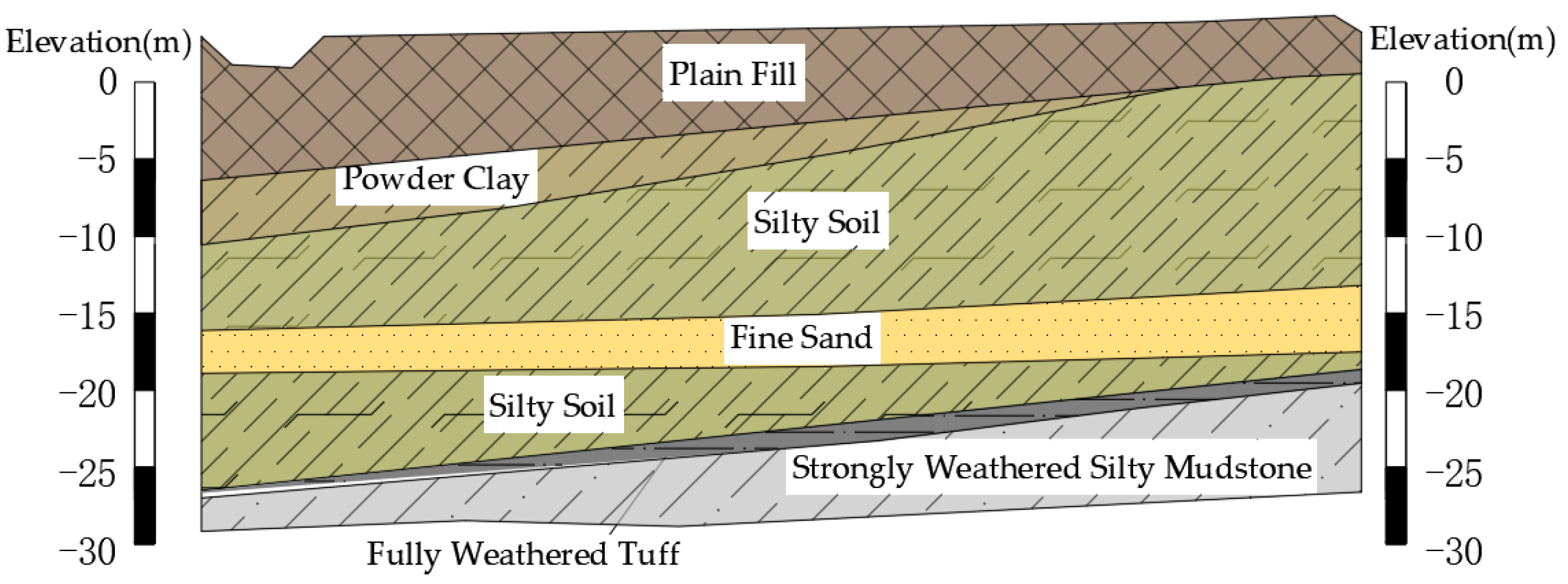
According to the regional geological survey, the geological conditions of the proposed road section are mainly: 3.5–9.8 m burial depth of artificial plain fill; 9.8–14 m burial depth of powder clay; and 14–19.5 m burial depth of silty soil. The geological conditions are shown in Figure 2.
The analysis of the geological situation in Figure 2 shows that the artificial plain fill and powder clay are weak soil layers with poor engineering shape; the silty soil and fine sand have poor adhesion and do not easily form piles; the strongly weathered and fully weathered layers soften easily and disintegrate when encountering water.

2.3. Surrounding Environment

The whole line is affected by high-pressure, low- and medium-pressure gas pipelines, and after a preliminary investigation it was found that high pressure pipeline whould not be relocated, so the protection of gas pipeline project became a pre-condition for soft foundation treatment and road construction. The gas pipeline was found to be buried at a depth of 2.58–12 m, with a net distance of 5–10 m between the two pipes and a diffuse orientation; the widening of the auxiliary road is closely linked to the river slope.

3. Programme Design Studies

3.1. Design Principles

Soils are deformed to varying degrees under the action of additional stresses, one is the compression of the soil particles caused by the action of the load, which is negligible because the soil particles themselves compress very little. The other is the compression of the overall soil volume by the pores between the soil particles squeezing each other under pressure [22]. For soft soil roadbeds, due to the additional stress, the super-pore water pressure dissipates continuously, the effective stress continues to grow, free water is discharged, and the soil volume is compressed, which in turn causes the roadbed to settle. In the construction of soft soil roadbeds with existing buried high-pressure gas pipes, controlling the settlement of the roadbed and minimising the residual settlement after construction is completed is an important prerequisite to ensure the normal use of high-pressure gas pipes and the normal operation of the road.

3.2. Commonly Used Soft Foundation Treatment Methods

Combined with the actual situation of the project, in order to seek the most suitable way of soft foundation treatment, the commonly used soft foundation treatment methods are compared and analysed. The specific application principles, advantages and disadvantages, and the scope of application are shown in Table 1 [23,24].

3.3. Programme Design

For the existing buried high-pressure gas pipe section under the Foqingcong Expressway, combined with the common soft foundation treatment methods, this paper designed two construction schemes from two perspectives: the pile composite foundation method and the light embankment method:
Scheme I: to ensure the safety of the existing high-pressure gas pipe, a reinforced concrete cover culvert is used to cover it; at the same time, to reduce the impact of the construction process on the pipe, combined with the geological situation, the foundation under the cover culvert is treated with cement mixing pile, plain concrete pile + sand bedding layer, and CFG pile + gravel bedding layer is used for larger depths;
Scheme II: using the feature of small capacity of FLC, FLC is used to deal with soft ground foundation for this special section.

4. FLC Feasibility Study

4.1. FLC Parameters Determination

FLC needs to conduct technical tests prior to construction to determine the mix parameters that meet the construction requirements. According to the actual project situation, the FLC mix ratio should be designed to meet the wet density and strength as shown in Table 2.
In order to determine the optimum construction mix ratio for FLC, three sets of test blocks were designed and made at each strength level according to the specification in this paper, and the test results are shown in Table 3. The results show that the construction compound ratio with serial number 1 was selected for both 0.8 MPa and 1.2 MPa strengths.

4.2. Load Stability Calculations

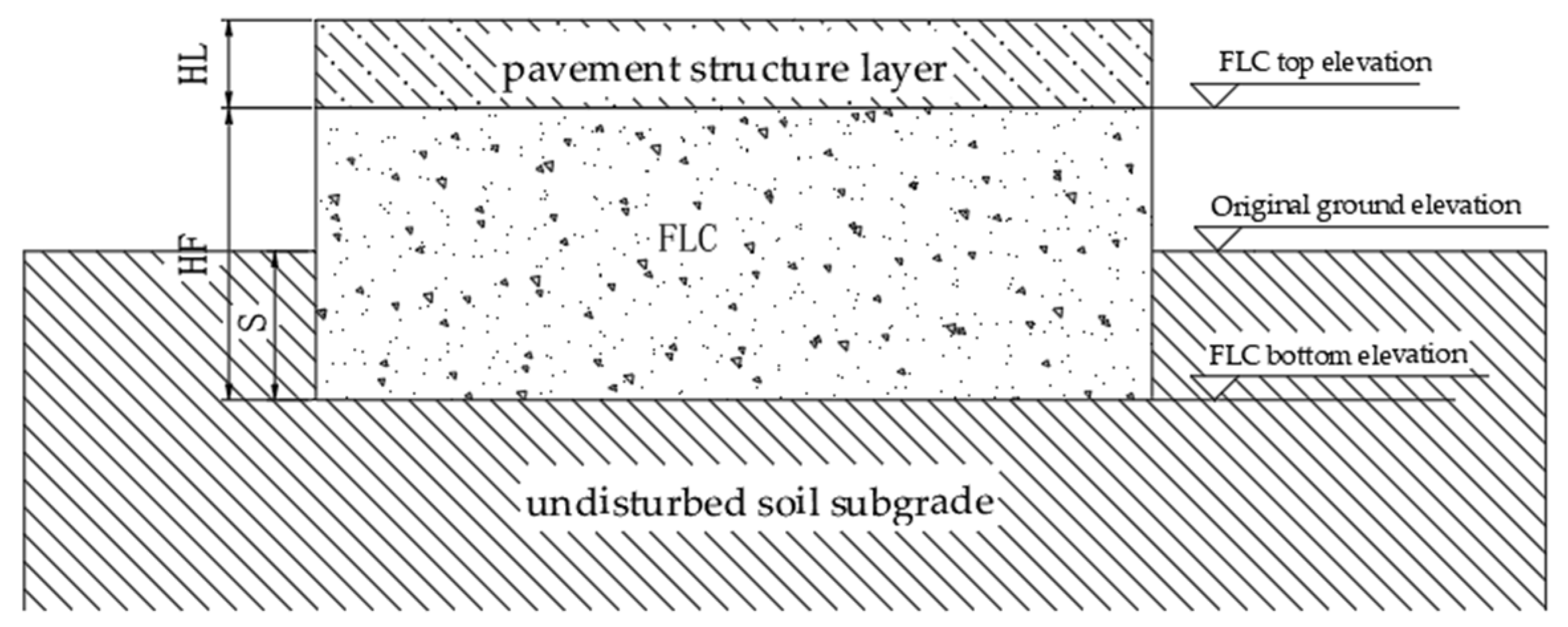
When pouring FLC on soft ground sections, problems such as uneven settlement may occur due to the increase in additional stresses, so it is essential to check the bearing capacity stability of FLC. A typical cross-section of the FLC is shown in Figure 3.
According to the specification of highway foundation design [25], the combined value of action effect should not exceed the allowable value of foundation bearing capacity, as shown in Formula (1). the FLC replacement filling calculation model is shown in Figure 4.
K 0 H L × γ L + H F × γ F + P 1 ,
where K 0 indicates the bearing capacity of the plain fill foundation; H L indicates the thickness of the structural layer of the pavement; γ L indicates the structural layer capacity of the pavement; H F indicates the thickness of the FLC; γ F is the natural capacity of the FLC; and P 1 is the live load of the pavement.
For the second phase project of the southern end of the Foqingcong Expressway under the buried existing high pressure gas pipe section to carry out load bearing stability calculations. According to the field survey report, the bearing capacity of the fill depth section is 110 KPa, and the live load of the pavement is converted to a uniform load of 15 KN/m3 (based on the empirical value of 70 tonnes of vehicles required for first-class highways and motorways). The load-bearing capacity stability test is shown in Formula (2).
K 0 = 110   KPa 0.83 × 26 + 5.63 × 5.5 + 15 = 67.545   KPa ,
The calculation results show that the use of FLC can meet the foundation bearing capacity stability requirements of the Fuqingcong Expressway project.
According to the project ground investigation report and borehole records, the FLC pre-replacement depth (−0.15 m) of the second phase of the Foqingcong Expressway project has not reached the depth of the water table (−2.1 m), so there is no need to carry out anti-floating test. For the small amount of pore water, impermeable geomembranes were laid at the top layer and steps.

4.3. Calculation of Additional Stresses and Settlements

According to the design principle of FLC replacement, different degrees of settlement will be generated when FLC is poured on soft soil roadbeds. Based on the additional stress calculation Formula (3) for the foundation soil, the additional stress and settlement calculation was carried out in conjunction with the actual situation of the existing buried high pressure gas pipe section. The results show that the effective additional stress in the subgrade is 12 KPa, as shown in Formula (4).
P 0 = H L × γ L + H F × γ F S × γ S ,
P 0 = 0.83 × 26 + 5.63 × 5.5 3.086 × 18 + 15 12   KPa ,
Choose the delamination total method for the settlement test. For the same soil layer each layer thickness h i according to 0.4 base width, while taking into account the depth of groundwater. For this section h i = 6 m, the water table elevation is −2.1 m, so the stratification above the water table is 2 m, the following stratification needs to be no greater than 6 m. Take the bottom of FLC as the depth Z = 0 m at which the soil self-weight stress σ c z is calculated, as shown in Table 4.
After dividing the foundation base into four equal parts a = 4.625 and b = 3.75, the corner-points method is applied to calculate the additional stress σ Z in the foundation under the centre point of the foundation, as shown in Formula (5).
σ Z = 4 K C P 0 ,
where, K C is the vertical additional stress coefficient at the corner point of the uniform rectangular load; P 0 = 12 Kpa.
Considering the soft soil roadbed with the depth of the foundation increases additional stress gradually decreases, often according to σ z 0.1 σ c z to determine the calculation depth [26], different depth additional stress calculation value as shown in Table 5, settlement calculation formula as shown in Formula (6).
S C = ( σ Z / E ) × h ,
where E is the compression modulus of the soil layer for settlement calculations and is taken as 4.74 MPa; h is the thickness of the soil layer.
The settlement amount can be calculated to be 0.009 m, which meets the settlement specification requirements according to the “Highway Roadbed Design Specification (JTG D30-2015)” regarding the allowable post-work settlement specified value (≤0.1 m) for roadbeds in soft soil areas [27]. However, in the process of soft foundation replacement, it is relatively difficult to protect existing gas pipelines, and the risk of pipeline deformation exceeds the standard is high [28]. There is no national standard for settlement control of buried pipelines in China, so this paper calculates the limit value for settlement control of pipelines through the allowable bending radius, and then judges the safety of buried pipelines under soft foundations [29].
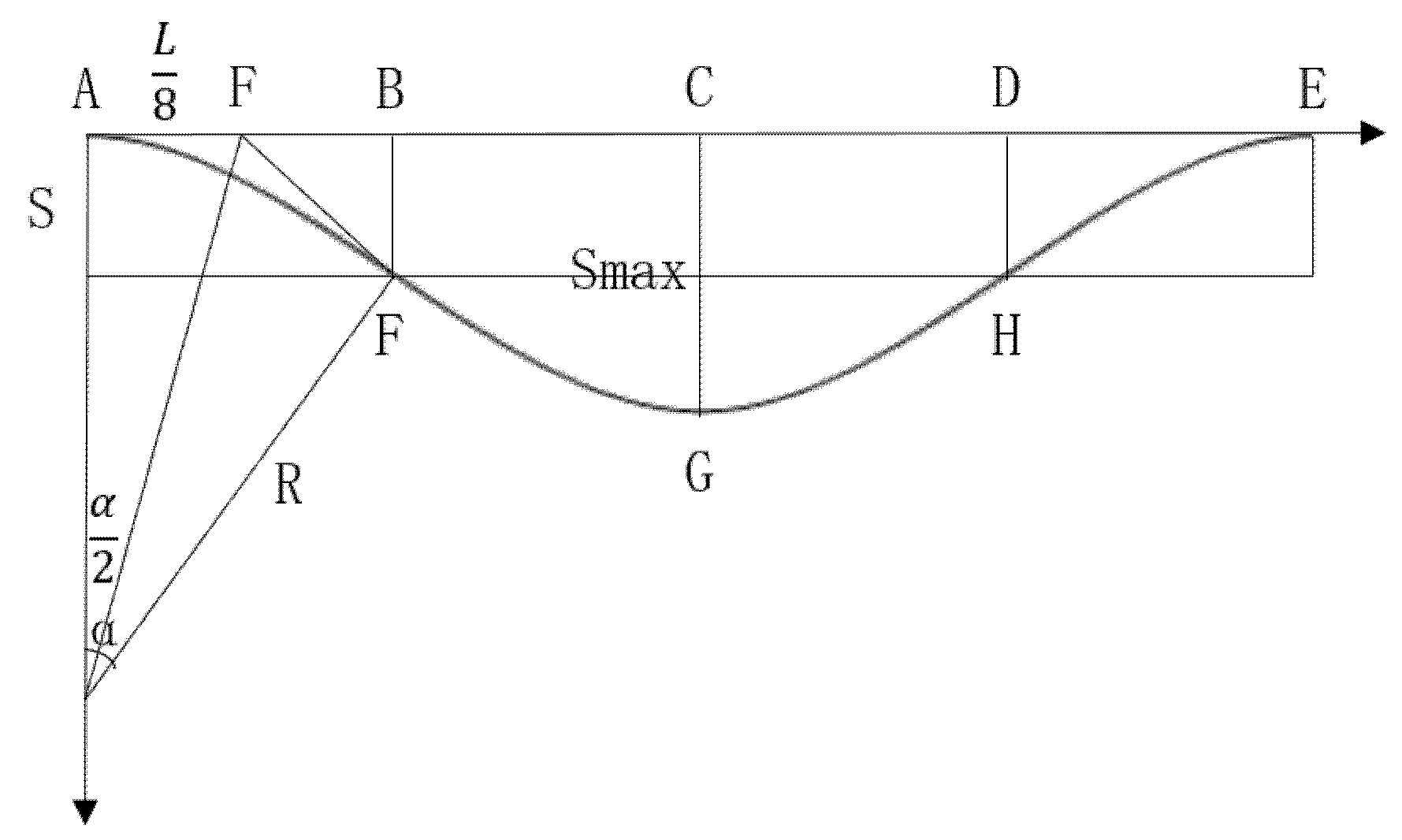
“Design Code for Gas Transmission Design Pipeline Engineering(GB 50251-2015)” stipulates that the calculation of radius of curvature of the vertical surface elastic laying pipeline is shown in Formula (7) [30]. The geometric relationship of pipeline settlement curve is shown in Figure 5, which is deformed from ABCDE to arc AFGHE, and the radius of curvature of arcs AF, FG, GH and HE are all R. Considering the pipe turning angle α ≤ 3°, the Formula (8) can be listed.
R = max 3600 1 cos α 2 α 4 D 2 3 , 1000 D ,
L 8 = R × tan α 2 ,
where D indicates the outer diameter of the pipe (cm) and is taken as 50.8 cm; L indicates the length of the monitoring pipe (m) and is generally an integer multiple of the pile distance and is taken as 50 m.
Combining Formulas (7) and (8) gives a turning angle α of 0.08° and a radius of curvature R of 8937.9 m. The maximum settlement value S max of the gas pipeline was calculated by substituting Formula (9) to be approximately 0.017 m. Therefore, when 0.009 m settlement occurred in the soft soil roadbed, there was almost no effect on the buried high-pressure pipeline, proving the feasibility of FLC application in the soft soil roadbed for both buried high pressure gas pipeline sections.
S max = 2 S = 2 R 1 cos α ,

5. Benefits Study

5.1. Safety Benefits Analysis

Scheme I is to use the soil bearing capacity between piles to transfer the load to deeper foundations, significantly reducing the lateral deformation of the soil between piles and foundation settlement. In the actual construction process, to ensure the safety of the buried high-pressure gas pipe, construction excavation should be mainly manual, and both sides of the pipe should not be excavated at the same time to avoid a large disturbance impact on the pipe. Improper construction techniques for plain concrete piles are prone to shrinkage, pile breakage and uneven pile strength. Combined with the actual geological situation, the silt-clay and sand layers will seriously affect the piling quality of the cement mixing pile; considering the extrusion of the soil on the pipe, the construction should be carried out by the long spiral borehole in-pipe pumping method.
FLC in Scheme II is a light embankment method, which compensates for the additional stresses imposed by the upper fill and traffic loads by replacing the fill layer. Due to the small capacity of FLC, the additional stresses in the soft soil layer are smaller than the effective stresses, which achieves the purpose of reducing the settlement of the soft soil roadbed [31].
Through analysis, it is found that the pile composite foundation is more complex than FLC construction technology, with lower safety and bigger impact on the surrounding environment, which requires various technical means to avoid the impact and interference with the existing buried high pressure gas pipe. After the construction of the piled composite foundation is completed, in order to meet the compaction requirements of the foundation, it is necessary to carry out layered rolling, and equipped with management personnel to monitor in real time; while FLC has high quality fluidity, pouring solidification is completed to meet the construction requirements, reducing the need for labour. It is concluded that Scheme II has better safety benefits.

5.2. Economic Benefits Analysis

Safety feasibility is an important prerequisite for the construction programme to be implemented, while economic management is a support point for engineering management, and good scientific economic efficiency is one of the values pursued in every engineering project. Therefore, the economic analysis of the construction section ensures the effectiveness of the construction programme.
The preliminary cost estimate of the existing buried high-pressure gas pipe section was made by consulting the Guangdong Province cost quotas and other specifications [32]. If plain concrete piles, cement mixing piles, CFG piles and reinforced concrete protective culverts are used (Scheme I) the cost is about 8.64 million; if foam lightweight concrete is used (Scheme II) the cost is about 7.57 million, which is 12% lower than Scheme I, saving about 1.07 million. The specific costs are shown in Table 6.

5.3. Ecological Benefits Analysis

In the context of China’s efforts to reduce carbon emissions, the construction industry has become a key component in helping to achieve China’s “emission peak and carbon neutrality” goals. The construction of road foundations consumes a large amount of non-renewable resources, the extraction, burning and emission of which can have a significant impact on the ecological environment. Therefore, in this paper, we decided to use carbon emissions as a parameter to calculate and compare Schemes I and 2, and then choose a more reasonable construction scheme.
It is complex to determine all environmental impacts based on whole process life cycle assessment (LCA) theory, so this paper chooses to use a simplified carbon emission assessment model [15,33,34], which mainly considers carbon emissions during the material production, transportation and construction phases, with the whole life cycle process shown in Figure 6 and the mathematical model for calculation shown in Formula (10).
E = E p + E t + E c ,
where E represents total carbon emissions over the life cycle; E p represents carbon emissions from the production of building materials; E t represents carbon emissions from the transportation phase of building materials; and E c represents carbon emissions from on-site construction.
Carbon emissions in the materialization phase are shown in Formula (11) [16]. Building materials are transported from the production site or sales yard to the construction site by rail, road or water, which consumes fossil energy and produces greenhouse gases. The analysis in this paper assumes that road transport is used (12), which is calculated using the “process energy” environmental impact inventory, as shown in the Formula [16]. The energy consumed for the operation of each piece of machinery and equipment during the construction phase is mainly diesel and electricity, and the resulting gas emissions are calculated as shown in Formula (13).
E p = Q p × M p ,
E t = D t × M t ,
E c = Q c × K c ,
where Q p denotes the amount of raw materialized blended into building materials, M p denotes the physical inventory of carbon emissions from the production of raw materials, D t denotes the transport distance, using the average transport distance of 67 km in China [35], M t denotes the carbon emission inventory of transporting building materials, Q c denotes the amount of fuel power used for construction machinery, K c denotes the carbon emission factor per unit of fuel for machinery.
Take the cement mix pile calculation as an example. The carbon emission inventories for the materialisation, transportation and construction phases of a unit length of cement mixing pile are shown in Table 7. The results of the calculations for Schemes I and II are shown in Table 8. It is concluded that the carbon emission of Scheme I is about 41,974,810 t and that of Scheme II is about 14,953,161 t. The total carbon emission of Scheme II is about 1/3 of that of Scheme I, and Scheme II has better ecological benefits.

6. Practical Analysis

6.1. Analysis of Settlement Test Results

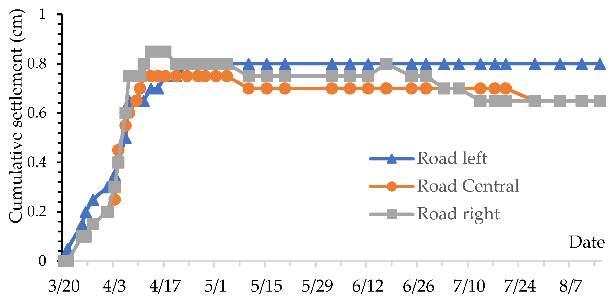
In order to study the ground deformation under load at different locations of the existing buried high pressure gas pipe section of the soft soil roadbed, the monitors chose to set up monitoring points at three locations on the left, middle and right of the road. The measurement period was from 20 March 2019 to 20 August 2019, and the measurement results are shown in Figure 7. As can be seen from it, the cumulative settlement of the foam lightweight concrete roadbed in the test section stabilised at less than 0.9 cm after work, satisfying the theoretical value.

6.2. Analysis of Earth Pressure Test Results

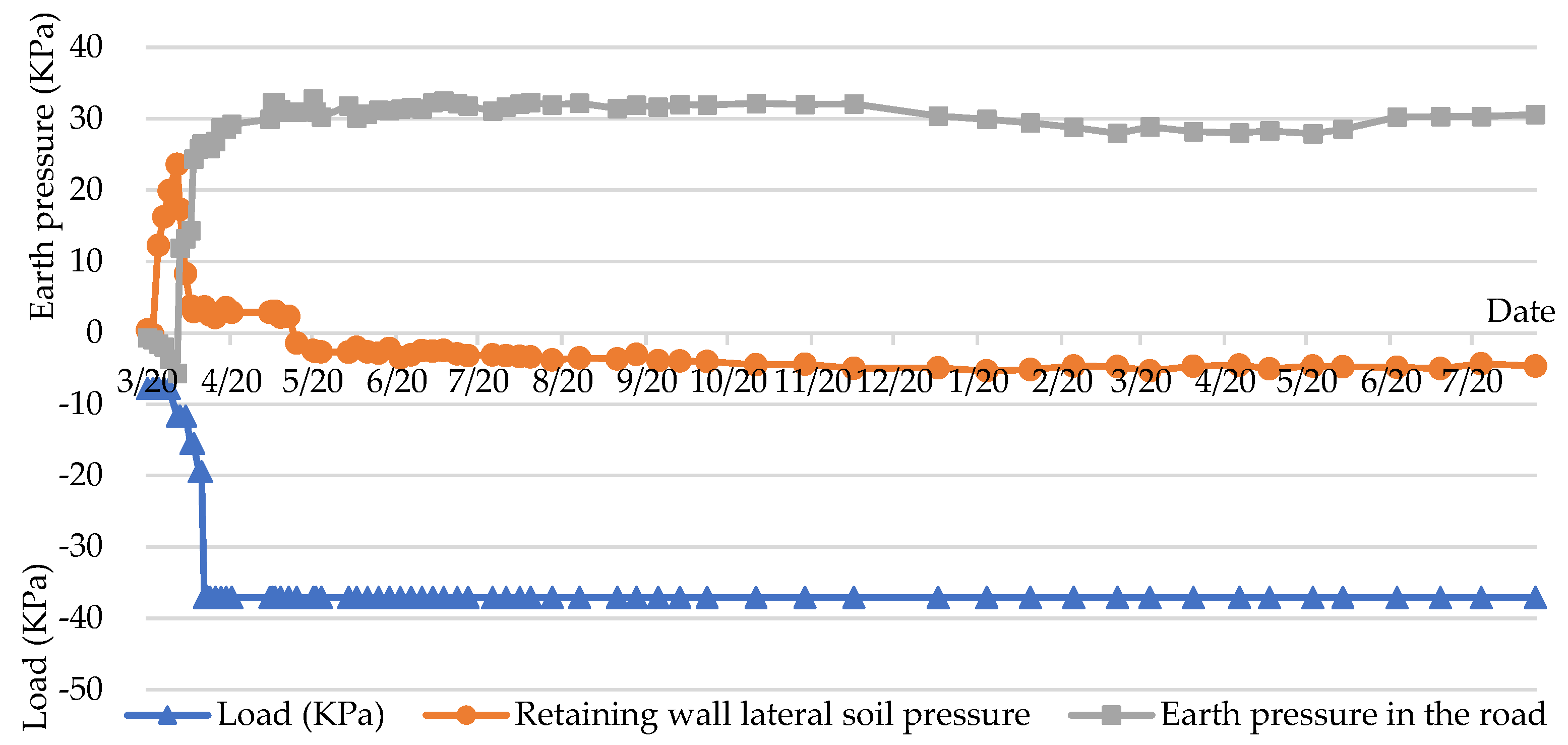
In order to study the soft soil roadbed both under the buried high pressure gas pipe section in the application of FLC load transfer law, in the middle of the roadbed and the retaining wall respectively arranged soil pressure box, soil pressure in the road and retaining wall lateral soil pressure with time change relationship as shown in Figure 8.

7. Conclusions

This paper relies on the soft foundation treatment project of the existing buried high-pressure gas pipe section of the Foqingcong Expressway. Through FLC design and calculation, analysis of the safety, economic and ecological benefits of different schemes, and field measurements, the feasibility and superiority of the FLC soft foundation treatment method compared with the pile composite foundation method in this special environment are demonstrated, and the following conclusions are obtained.
(1)
Through the existing buried under the high-pressure pipeline bending radius tolerance worth out the calculation method of pipeline settlement control limit, verify the feasibility of the application of FLC in the construction of the highway soft foundation of the existing buried under the high pressure gas pipeline section, for the existing buried under the pipeline settlement ideas calculation provides a new idea;
(2)
Using carbon emissions as a parameter in the ecological benefit analysis of the two schemes, a simple carbon emission assessment model was determined based on LCA theory, which improved the one-sidedness of the safety benefit and economic benefit analysis, and proved that the carbon emission of the FLC light embankment method is less than that of the traditional pile foundation construction method, which is in line with the requirement of coordinated and sustainable development of human production activities and natural ecosystems, and is of great significance to the green transformation of the construction industry and the achievement of the double carbon target;
(3)
Relying on the FLC soft foundation treatment of the existing buried high-pressure gas pipeline section of the Foqingcong Expressway, the project cost was reduced by 12% and the carbon emission was reduced by 1/3 under the premise of safety and stability. This study also fully proved the feasibility of FLC application in the process of soft soil roadbed treatment of the existing buried pipeline, which has reference significance for the optimal design of similar projects.

Author Contributions

Conceptualization, Z.J., X.G., X.F. and D.C.; methodology, Z.J. and X.G.; software, X.G.; validation, Z.J. and X.G.; formal analysis, Z.J. and X.G.; investigation, X.G. and X.F.; resources, Z.J., X.F. and D.C.; data curation, X.G.; writing—original draft preparation, X.G. and X.F.; writing—review and editing, Z.J., X.G. and D.C.; visualization, X.G.; supervision, Z.J.; project administration, Z.J. and D.C.; funding acquisition, Z.J. and D.C. All authors have read and agreed to the published version of the manuscript.

Funding

This research was funded by the National Key Research and Development Program of China (No. 2016YFC0701308).

Data Availability Statement

Not applicable.

Conflicts of Interest

We declared that we have no conflict of interest in this work.

References

  1. Xi, L. Comparison and selection of soft foundation treatment schemes for road and bridge junction. Ind. Constr. 2017, 47, 342–344+349. (In Chinese) [Google Scholar]
  2. Meilan, Z.; Haichen, Y.; Xiaoshan, L. Study on the Parameters of Buried Pipelines under Highway to Ensure Safety. Munic. Technol. 2021, 39, 119–124. (In Chinese) [Google Scholar]
  3. Otani, J.; Mukunoki, T.; Kikuchi, Y. Visualization for engineering property of in-situ light weight soils with air foams. Soils Found. 2008, 42, 93–105. [Google Scholar] [CrossRef] [Green Version]
  4. Nambiar, E.K.K.; Ramamurthy, K. Fresh state characteristics of foam concrete. J. Mater. Civ. Eng. 2008, 20, 111–117. [Google Scholar] [CrossRef]
  5. Jones, M.R.; Ozlutas, K.; Zheng, L. Stability and instability of foamed concrete. Mag. Concr. Res. 2016, 68, 542–549. [Google Scholar] [CrossRef] [Green Version]
  6. Song, Y.; Lange, D. Influence of fine inclusions on the morphology and mechanical performance of lightweight foam concrete. Cem. Concr. Compos. 2021, 124, 104264. [Google Scholar] [CrossRef]
  7. Shi, X.; Huang, J.; Su, Q.J.C.; Materials, B. Experimental and numerical analyses of lightweight foamed concrete as filler for widening embankment. Constr. Build. Mater. 2020, 250, 118897. [Google Scholar] [CrossRef]
  8. Yu, H.; Wang, Y.; Chao, Z.; Peng, W.; Cen, Y. Study on Subgrade Settlement Characteristics After Widening Project of Highway Built on Weak Foundation. Arab. J. Sci. Eng. 2017, 42, 1–10. [Google Scholar] [CrossRef]
  9. Hui, L. Rapid construction method of foam lightweight soil in subway emergency rescue. J. Henan Sci. Technol. 2013, 14, 24–25. (In Chinese) [Google Scholar]
  10. Wenjie, C.; Zhiyong, D.; Qingmeng, M.; Qingchang, Q. Protection Technology of Reinforced Concrete in Cold Area and Saline Soil Environment. Constr. Technol. 2016, 45, 544–546. (In Chinese) [Google Scholar]
  11. Liu, X.; Ni, C.; Zhang, L.; Sheng, K.; Hong, B. Durability Assessment of Lightweight Cellular Concrete in Subgrade by the Method of Analytic Hierarchy Process Combined with Fuzzy Comprehensive Evaluatio. Math. Probl. Eng. 2019, 2019, 4915870. [Google Scholar]
  12. Qizhen, J.; Zhongping, C.; Jianbin, W.; Jifu, L. Determination method of light soil thickness for soft foundation embankment replacement. Highway 2019, 64, 84–88. (In Chinese) [Google Scholar]
  13. Wei, Z.; Kui, T. Application and technical improvement of foam lightweight soil. Jiangxi Build. Mater. 2016, 10, 100–102. (In Chinese) [Google Scholar]
  14. Mengyuan, S.; Zhijie, W.; Guangqing, Y.; Dan, L. Calculation and Evaluation of Carbon Emission from Different Types of Retaining Structures. Railw. Surv. 2020, 46, 41–48. (In Chinese) [Google Scholar]
  15. Peipei, H. Study on the Life-cycle Energy Consumption of New-type Wali Material. Master’s Thesis, Hubei University of Technology, Wuhan, China, 2013. (In Chinese). [Google Scholar]
  16. Wenguang, C. The Comprehensive Evaluation of Soft Soil Foundation Treatment in LCA Method. Master’s Thesis, Qingdao University of Technology, Qingdao, China, 2012. (In Chinese). [Google Scholar]
  17. Zhijia, X.; Liangchen, L.; Changgen, Y.; Chao, J.; Yaxin, W.; Qi, X.; Jiang, L. Evaluation of energy consumption and carbon emissions for construction of wet and soft loess subgrade in highway engineering. J. Dalian Univ. Technol. 2021, 61, 522–530. (In Chinese) [Google Scholar]
  18. Falliano, D.; Domenico, D.D.; Sciarrone, A.; Ricciardi, G.; Gugliandolo, E.J.T.; Mechanics, A.F. Fracture behavior of lightweight foamed concrete: The crucial role of curing conditions. Theor. Appl. Fract. Mech. 2019, 103, 102297. [Google Scholar] [CrossRef]
  19. Cai, D.G.; Wei, S.W.; Ye, Y.S.; Zhang, Q.L.; Li, Z.G.; Li, S. Mechanical properties of lightweight foam concrete filler for roadbed of high-speed railway. Arab. J. Geosci. 2021, 14, 1–10. [Google Scholar] [CrossRef]
  20. Cong, M.; Bing, C. Properties of a foamed concrete with soil as filler. Constr. Build. Mater. 2015, 76, 61–69. [Google Scholar] [CrossRef]
  21. Gopalakrishnan, R.; Sounthararajan, V.M.; Mohan, A.; Tholkapiyan, M. The strength and durability of fly ash and quarry dust light weight foam concrete. Mater. Today Proc. 2019, 22, 1117–1124. [Google Scholar] [CrossRef]
  22. Xun, L. The Research on Settlement Deformation Observation and Prediction Methods of Soft Soil Foundation. Master’s Thesis, Changsha University of Science & Technology, Changsha, China, 2017. (In Chinese). [Google Scholar]
  23. Shengyun, P. Application of Plastic Drainage Plate in Soft Soil Foundation Treatment. Master’s Thesis, Zhejiang University, Hangzhou, China, 2019. (In Chinese). [Google Scholar]
  24. Yan, X. Research on foundation treatment method of Binhai Avenue in Putian, Fujian. Master’s Thesis, Shenzhen University, Shenzhen, China, 2018. (In Chinese). [Google Scholar]
  25. JTG 3363-2019; Specifications for Design of Foundation of Highway Bridges and Culverts. People’s Transportation Press: Beijing, China, 2019. (In Chinese)
  26. Guangxin, L. Advanced Soil Mechanics; Tsinghua University Press: Beijing, China, 2004. (In Chinese) [Google Scholar]
  27. JTG D30-2015; Specification for Design of Highway Subgrade. People’s Communications Press: Beijing, China, 2015. (In Chinese)
  28. Dongping, Z.; Sixun, W.; Luwei, W.; Huachang, F.; Deyong, W. Study on Settlement Control Standard of Underground Gas Pipelines Affected by Tunnel Underpass Construction. Mod. Tunn. Technol. 2021, 58, 258–264. (In Chinese) [Google Scholar]
  29. Hao, Z. Underground Natural Gas Pipeline Allowable Settlement Deformation Calculation. Shanghai Gas 2010, 04, 14–15+46. (In Chinese) [Google Scholar]
  30. GB 50251-2015; Code for design of gas transmission pipeline engineering. China Planning Press: Beijing, China, 2015. (In Chinese)
  31. Fei, D. Research on Foundation Treatment of Soft Soil Subgrade of the East Hangzhou Railway Station Building. Railw. Stand. Des. 2018, 62, 31–35. (In Chinese) [Google Scholar]
  32. Guangdong Provincial Department of Housing and Urban-Rural Development. Comprehensive Quota of Housing Construction and Decoration Engineering in Guangdong Province: 2018; Huazhong University of Science and Technology Press: Wuhan, China, 2018. (In Chinese) [Google Scholar]
  33. Shillaber, C.M.; Mitchell, J.K.; Dove, J.E. Energy and Carbon Assessment of Ground Improvement Works. I: Definitions and Background. J. Geotech. Geoenvironmental Eng. 2016, 142, 04015083. [Google Scholar] [CrossRef]
  34. Cole, R.J.; Kernan, P.C. Life-cycle energy use in office buildings. Build. Environ. 1996, 31, 307–317. [Google Scholar] [CrossRef]
  35. Yongxin, Z.; Ying, S. Assessment of building energy consumption and environmental impact based on life cycle theory. Constr. Manag. Mod. 2009, 23, 109–112. (In Chinese) [Google Scholar]
Figure 1. Schematic diagram of the project effect.
Applsci 12 10119 g001
Figure 2. Geological map.
Applsci 12 10119 g002
Figure 3. Cross-sectional view of foam lightweight concrete.
Applsci 12 10119 g003
Figure 4. Calculation model of foam lightweight concrete replacement.
Applsci 12 10119 g004
Figure 5. Schematic diagram of pipeline settlement.
Applsci 12 10119 g005
Figure 6. Life-cycle carbon emissions flow chart.
Applsci 12 10119 g006
Figure 7. Subsidence measurement results.
Applsci 12 10119 g007
Figure 8. Earth pressure measurement results.
Applsci 12 10119 g008
Table 1. Comparison of different soft base treatment methods.
TreatmentPrincipleAdvantagesDisadvantagesScope of Application
drainage consolidationThrough the pressurisation and drainage systems the free water in the soft ground is induced to drain through the gaps, the water content of the soil is reduced, the effective stress is continuously increased, and the bearing capacity of the soil is improved.Simple method, large treatable depth and low cost.The long construction period, the large geological area affected and the dynamic equilibrium state of the surrounding original buildings.A soft clay layer with a high water content.
replacement bedding methodThe use of excavated stone slag, sand and gravel and other materials with good permeability to replace the soil layer, filling and compaction in layers to improve the base bearing capacity, control settlement and change the permeability of the soil layer.A radical improvement to the foundation, simple to implement, fast to construct and cost effective.The shallow depth of the replacement fill requires a large amount of permeable material and cannot treat soft foundations with overburden.Only suitable for shallow replacement where the depth of the replacement is not greater than 3 metres and is less affected by external forces.
geogridsGrid constructionTo channel infiltration works, isolate the partitioning effect and form a transversely and longitudinally bonded monolithic structure, this is often achieved by means of geogrids, grids, etc.Practical and cost effective.The surface cover is prone to erosion and affects the stability of the bank.Commonly used after soft foundation treatment and before filling with sand bedding.
rigid pile composite foundationsplain concrete pilesThe holes are first cut to the design depth at the construction site, then the concrete is poured and compacted into shape.High load-bearing capacity, low settlement, mature construction techniques, easy to control the quality of construction.High cost and long construction period.Suitable for all kinds of soft soils up to 20 m thick.
CFG pile (Cement Fly Ash Gravel pile)The squeezing action is used to densify the uncompacted foundation soil and improve the overall stability and bearing capacity of the foundation.The treatment depth is large, the construction is convenient, the settlement is small and the effect of improving the bearing capacity of the natural foundation is remarkable.The construction process is difficult, the monopile load capacity is low, and the piling results are related to the construction technology and environment.Suitable for silty soils, miscellaneous fills, saturated and unsaturated clayey soils, etc. with large thicknesses.
cement mixing pilesThe cement slurry, lime and other curing agents are mixed with the foundation soil to form a columnar cement soil, which in turn improves the geological environment, increases the compression modulus of the soil and reduces settlement.Significantly improves the overall bearing capacity of the soil and is fast to construct.The construction process is complex and the quality of the piles is influenced by construction experience and the geological environment.Suitable for soft foundations such as silt, clay and chalk with a soft soil thickness of less than 12 m.
ultralight fill replacement methodFoam lightweight Concrete (FLC)By reducing the self-weight of the road base fill to reduce the additional stress on the foundation, the effect of improving the stability of the foundation and reducing post-work settlement is achieved.Lightness, adjustable strength, high fluidity, self-supporting after curing, water resistance, durability, etc.High unit costCommonly used to resolve differential settlement, frost protection, bridge abutment backfill, construction and maintenance of highways, etc.
Table 2. FLC key design performance indicators.
Distance from the Bottom of the Structural Layer of the Road/mWet Density Rfw/(kg·m−3)28 d Compressive Strength/MPa
0~0.8Rfw ≤ 650≥1.2
>0.8Rfw ≤ 650≥0.8
Table 3. FLC test results for different mix ratios.
Strength Grade/MPaWater-Cement RatioComposition of FLC per Square/(kg/m3)Bubble Rate/%Design Wet Density/(kg/m3)Flow Value7 d Compressive Strength/MPa28 d Compressive Strength/MPa
CementWater
0.80.6531920768.75601800.560.86
0.6530920169.65451750.470.75
0.6532821367.85751820.60.92
1.20.6535022765.66101860.631.25
0.6535923364.76251850.691.3
0.6534022166.55951800.591.18
Table 4. Soil self-weight stress.
Z/m024
σ c z / K N m 2 5490116
Table 5. Additional stress values at different depths.
Z/mZ/b K C σ z 0.1 σ c z
000.25121.8
20.530.2311.195.4
41.070.188.5516.8
Table 6. The specific cost of the construction plan.
Single ProjectScheme I/CNYScheme II/CNY
earthworks866,097.355682,558.62
plain concrete piles2,908,879.97
CFG piles287,922
cement mixing piles551,403.73
sand and gravel bedding1,181,795.615
steel-plastic grating718,177.85
plastic drainage board102,693.481
cast-in-place cover slab C35 concrete1,021,311.35
Cast-in-place cover reinforcement1,004,711.87
FLC 6,749,642.1
clay borders 142,409
Total816,421,993.2217,574,609.72
Table 7. Inventory of carbon emission per unit length of cement mixing pile.
PhaseProjectUnitCO2SO2NOxCOQuantityCarbon Emissions/t
Materialization phaseP.S32.5kg/t677.680.2021.0870.29250 kg0.034
Transportation phaseroad transportationkg/t·km18.214,20012.926167 km48.549
Construction phasedeep mixers (thermal)kg/wh1.140.00010.00520.0028227 kwh260.617
lifting equipments
(diesel)
kg/kg0.07340.00260.00030.000732.25 kg0.002
Curing agent preparation systems (thermal)kg/wh1.140.00010.00520.002840.17 kwh46.119
Table 8. Scheme I and II carbon emission inventories.
ProjectQuantityUnit Carbon Emissions/
(kg·m−1(m−3))
Total Carbon Emissions/tTotal Carbon Emissions of the Programme/t
Plain concrete piles29,661.501,217,218.1336,104,515.450Scheme I: 41,974,810
CFG piles4900.80324,558.32671,590,595.447
Cement mixing piles12,044.60355,320.98584,279,699.146Scheme II: 14,953,161
FLC27,319.90547,335.8514,953,160.752
Publisher’s Note: MDPI stays neutral with regard to jurisdictional claims in published maps and institutional affiliations.