Abstract
Patrol missiles are a common type of unmanned aerial vehicle, which can be efficiently used for reconnaissance and sensing. In this work, target detection and the damage assessment of typical mobile ground targets by patrol missiles are studied, and a new method, combining the YOLO v3 with the VGG networks, is proposed for the problem. Specifically, with YOLO v3 as the precursor, the proposed method can detect, classify, and localize ground targets accurately and quickly. Then, the image blocks of detected targets are fed into the lightweight VGG networks, which can evaluate their damage level coarsely. Meanwhile, based on class activation mapping (CAM) and deconvolution, we further analyse the activation intensity of clustered convolution kernels, which helps determine whether the targets’ key components are destroyed. Unlike traditional image change detection methods, which require images before and after a strike for comparison, the proposed method learns the target model through extensive training and can assess the target’s damage status in a timely and online manner. Compared to previous learning-based methods, our detailed analysis with convolutional feature visualization of the damaged targets and their components gives a more interpretable perspective. Finally, Unity simulation experiments prove the proposed method’s effectiveness, which improves the accuracy of damage level assessment by 16.0% and 8.8% compared with traditional image-change-detection-based methods and the two-CNN learning-based method. The convolutional feature clustering method evaluates the status of the targets’ key components with an accuracy of 72%.
1. Introduction
Damage assessment of targets based on images has been a significant problem in intelligent military perception. The U.S. Joint Chiefs of Staff defined the Battle Damage Assessment (BDA): The timely and accurate estimate of damage resulting from the application of military force, either lethal or non-lethal, against a predetermined objective [1].
This work focuses on the damage assessment for mobile ground targets, such as tank, supply vehicle, and tent. Unlike traditional fixed ground targets in previous works, mobile ground targets are more flexible. They are moving on the ground for certain specific tasks and their positions are constantly changing in real-time. Therefore, the damage assessment method for mobile ground targets should also operate in real-time and only on the UAV’s hardware, without the participation of a rear control center.
However, since most of the existing works evaluate the damage status of the target by detecting the changes in images before and after a strike, real-time and online damage assessment is nearly impossible for them. Specifically, they are often divided into three parts: register the images before and after the strike, detect the struck target from the images, and assess the damage level based on the changes in the geometric and texture features [2]. Since the high-precision registration of the images from before and after the strike is a complex and time-consuming process, it is always performed offline at the control center rather than online on only the UAV’s hardware.
The traditional image-change-detection-based methods are mainly for fixed targets. Since they need high-precision registration of the images from before and after the strike, they are unavailable for mobile ground targets. Although learning-based methods can extract deep semantic information and detect mobile ground targets in real-time, they often suffer more from the influence of different inter- and intraclass features. Therefore, these existing methods are hard to extend to mobile targets.
Moreover, most existing works focus on the damage level assessment for the whole targets, lacking of further status evaluation for their functional components. However, such information is also very important for the evaluation of the various specific abilities of mobile ground targets. For example, a supply vehicle with destroyed wheels will no longer be able to move, making it easier to be attacked. A similar work can be found in [3], which analyzed the structure of typical fixed ground target based on expert knowledge and realized a functional damage assessment. However, it is hard to extended to various mobile ground targets. Due to the stationary nature of each part of a fixed target, there is a stable position relationship between the key components and the overall body of the target. In contrast to the case of a fixed target, the position relationship of a mobile target will change significantly with the target’s movement and the observation angle. In addition, methods of functional damage assessment based on expert knowledge are often designed for large-scale general targets and require a large amount of data maintenance and management. Applying such methods to mobile targets is difficult due to the wide variety of mobile targets and their complex structural variations.
To tackle the above problems, we propose a real-time detection and timely damage assessment method named YOLO-VGGNet for mobile ground targets. Firstly, with YOLO v3 as the precursor, the proposed method detects, classifies, and localizes mobile ground targets accurately and quickly. Secondly, the image blocks of detected targets are fed into the lightweight VGG networks, which output the coarse results of damage level assessment. Later, based on class activation mapping (CAM) and deconvolution, we further analyze the activation intensity of clustered convolution kernels and determine whether the targets’ key components are destroyed.
The innovations of this paper are as follows: (1) We propose a real-time detection and timely damage assessment method for mobile ground targets, YOLOVGGNet, which can be performed based on online perception; (2) We cluster and visualize the convolution kernels based on CAM and deconvolution, which not only helps determine whether the targets’ components are damaged or not, but also provides a more interpretable perspective for learning-based methods; (3) We build up a simulation system based on Unity and prove the effectiveness of the proposed method by extensive experiments. Experimental results show that the proposed method improves the accuracy of damage level assessment by 16.0% and 8.8% compared with traditional image-change-detection-based methods and the two-CNN learning-based method. The convolutional feature clustering method evaluates the status of the targets’ key components with an accuracy of 72%.
This paper is organized as follows: Section 2 introduces existing works on damage assessment. Section 3 designs the novel damage level assessment method named YOLO-VGGNet. Section 4 mainly describes damage assessment of the target’s components based on convolution feature clustering, and a detailed description of convolutional feature clustering can be found here. The simulation system and experimental result are shown in Section 5. Section 6 concludes the paper.
2. Related Work
The core of the damage assessment process is the analytical assessment method used. In addition to manual interpretation, traditional methods mainly include Bayesian networks [4], principal component analysis (PCA) [5], and image feature understanding [6].
Evaluation methods based on Bayesian networks mostly rely on machine interpretation, which can synthesize various types of information and have the advantages of a short processing time and the ability to quantitatively analyze problems that are subject to uncertainty. Ma et al. made full use of the advantages of Bayesian networks in computing uncertain problems to build a Bayesian model for target damage assessment. By using GeNIe software, this Bayesian model can assess the damage effect on target ships [7]. Cheng et al. used UAV reconnaissance technology to obtain image information of vehicle targets and analyzed the damage features using Bayesian networks to establish a functional damage assessment model [8]. By incorporating a dynamic Bayesian network analysis of a damage time stream, Yang effectively overcame the subjectivity and uncertainty of traditional methods and achieved a higher assessment accuracy [9]. Nevertheless, although they are beneficial for solving uncertain problems, Bayesian-based evaluation methods cannot make use of human experience and knowledge and often cannot grasp principal contradictions.
PCA-based methods mainly adopt the idea of dimensionality reduction to transform complex feature representations of images into only a few evaluation metrics, which are then used as quantitative features to evaluate the degree of image change [10]. Li et al. fused the advantages of PCA and synthetic aperture radar (SAR) imaging with multitexture feature extraction to evaluate the damage to ground buildings and reduce the amount of data computation [11]. Wu et al. combined PCA with a convolutional mapping network to achieve change detection for high-resolution images acquired in different time periods [12]. Yousif O and Ban Y proposed an improved PCA-NLM method for urban development change detection based on SAR images from different time periods [13]. PCA-based methods can reduce the volume of data to be processed and capture principal contradictions. However, they are less robust to image interference.
With the rapid development of remote sensing, image processing, and other related technologies, image-feature-understanding-based methods have become the focus of current research on damage assessment, which are generally divided into two categories: image-segmentation-based [14] and target-detection-based [15] methods. They are more widely adaptable, more resistant to interference, and more in line with human visual understanding than methods based on pixel and texture change detection. However, complex structures and uncertain environments make it difficult for the adaptability and accuracy of such assessment algorithms to meet the demands of application.
The key to traditional damage assessment methods is the detection of changes in images acquired before and after a strike, which is essentially a feature extraction problem. Multiple errors are inevitably introduced when using various image processing algorithms, such as image preprocessing, image registration, and image radiation correction. At the same time, it is not easy to build an effective assessment model from a limited sample due to the specificity and confidentiality of the attacked targets. Moreover, such methods often rely on a control center, and the assessment results will inevitably have a certain lag, which is intolerable for some tasks with high real-time requirements [16].
Although much work has been done on image-change-detection-based damage assessment, these methods have seldom paid attention to the problems of achieving online and real-time performance. The emergence of learning-based methods provides a solution to these problems. In recent years, convolutional neural networks (CNNs) have achieved great success in computer vision and pattern recognition. In tests on many large datasets, deep CNNs have exceeded human recognition rates and have a faster detection speed [17]. Considering the advantage of extracting deep advanced semantic features through learning based on large amounts of data, the application of learning-based methods for damage assessment has also attracted widespread attention [18,19,20]. Zhang et al. proposed a new baseline dataset for road damage detection with attention learning. Their dataset was collected by professional onboard cameras and is manually labeled with eight damage categories of three degrees (mild, moderate, and severe), which can effectively help promote research on the automated detection of road damage [21]. Kumar et al. applied a Mask-RCNN to evaluate the abrasion areas of vehicles involved in road traffic accidents to reduce the workload of insurance company personnel [22].
Damage assessment based on a single-stage CNN requires considerable calculation for each image. When faced with a large amount of data that need evaluation, this approach is very time-consuming. Therefore, many researchers have used lightweight networks to first determine whether a target is damaged to improve the evaluation efficiency. Calton et al. designed a two-CNN disaster assessment network to evaluate the extent of the damage inflicted on coastal cities and structures. Two neural subnetworks are applied to evaluate whether houses are affected by floods and the damaged components of the houses [23]. In the same way, Alqahtani et al. designed a two-CNN learning-based damage assessment method for mechanical structures. Two subnetworks were built to evaluate whether a structure is damaged and the degree of damage [24]. The two-CNN evaluation approach significantly improved the accuracy and computational efficiency.
However, although the existing methods based on two-CNN can achieve improved evaluation efficiency and obtain better results by extracting deep semantic features, the objects of evaluation belong to a single target type. The relationship between the two CNNs in the processing approach is relatively weak.
How do we evaluate the damage degrees of different types of targets? Is such a two-CNN evaluation method effective for this purpose? Some researchers have considered judging the target type based on the first subnetwork. To evaluate the damage degrees of different houses after a typhoon, Xu et al. combined two CNNs. The first subnetwork was used to distinguish different types of houses and localize their positions, and the second was used to evaluate the degree of damage to each house based on prior information from the first CNN [25]. Similarly, to evaluate the degrees of damage caused by different natural disasters, Tang et al. concatenated two CNNs to classify the disaster type and damage level [26]. However, the relationship between the two CNNs was still weak, depending only on classification information. We propose a strongly concatenated two-stage learning-based method for mobile ground targets based on prior YOLO detection, classification, and localization information.
Despite the undeniable progress achieved by learning-based damage assessment approaches in recent years, the explainability of deep neural networks presents an unavoidable problem. Due to the lack of analysis of the intermediate results, it is difficult to give concrete reasons for the experimental results obtained, thereby limiting the further applications of such learning-based approaches, especially in the fields of automatic vehicle driving and medical disease diagnosis. Therefore, many existing works have focused on the operating mechanisms and feature extraction logic of CNNs, a topic known as explainable AI (XAI) [27]. By visualizing the features extracted from intermediate convolutional layers, the study of feature visualization can effectively improve the understanding of XAI [28]. Feature visualization has functions similar to those of image feature extraction based on computer image processing [29]. If we could utilize such visualized features, this would be beneficial in enhancing the ability of CNNs to solve damage assessment problems.
Convolutional feature visualization methods generally include intermediate feature layer visualization [30], class activation mapping(CAM) [31], and deconvolution [32]. In CAM, the importance of each component of an image to the final decision is represented by generating a heatmap as an intuitive representation of the weight distribution. Selvaraju et al. proposed Grad-CAM to make CAM more universal [33]. Grad-CAM optimizes the backpropagation process and calculates the weights corresponding to each feature map in a convolutional layer by performing global averaging of the gradients and summing the weights. Based on Grad-CAM feature visualization, Banerjee et al. introduced feature information to evaluate the environmental damage after a typhoon [34], and Chen explained the results of building damage classification and derived the image basis for the neural network’s determinations [35]. They both obtained better damage assessment results by introducing XAI theory into the damage assessment field.
Not only Grad-CAM but also other works on XAI-based feature visualization have enabled significant progress. Zhang et al. increased the credibility of diagnostic results based on XAI [36]. Matin et al. modified a dataset and training model based on XAI and achieved a better post-disaster building damage assessment effect [37]. Nevertheless, the current XAI-based methods also have the shortcoming that they cannot work in a real-time and online manner. The reason is that the neural network structure is relatively complex, and considerable weight information is lost during backpropagation, leading to high time consumption during processing.
The development of XAI theory not only increases trust in the results generated by AI systems but also provides new assistance in solving existing problems. In deconvolution visualization [32], a feature map is taken as the input to perform the inverse of convolution, thereby mapping the results to the original pixel space to display the features extracted by the convolution kernels of each layer. The latest research on the visualization of convolutional features provides novel approaches to damage assessment problems. LayerCAM [38] can produce reliable class activation maps from any CNN layer by employing element-level weights. Score-CAM [39] gets rid of the dependence on gradients by obtaining the weight of each activation map through its forward passing score on the target class. The final result is obtained by a linear combination of weights and activation maps, which achieves better visual performance and fairness for explaining the decision-making process.
To combine the advantages of learning-based and XAI-based methods, we propose the YOLO-VGGNet method. It can not only meet the requirements of real-time detection and timely damage assessment online but also fully utilize the visualized features from the convolutional layers.
3. Target Detection and Damage Level Assessment Based on YOLO-VGGNet
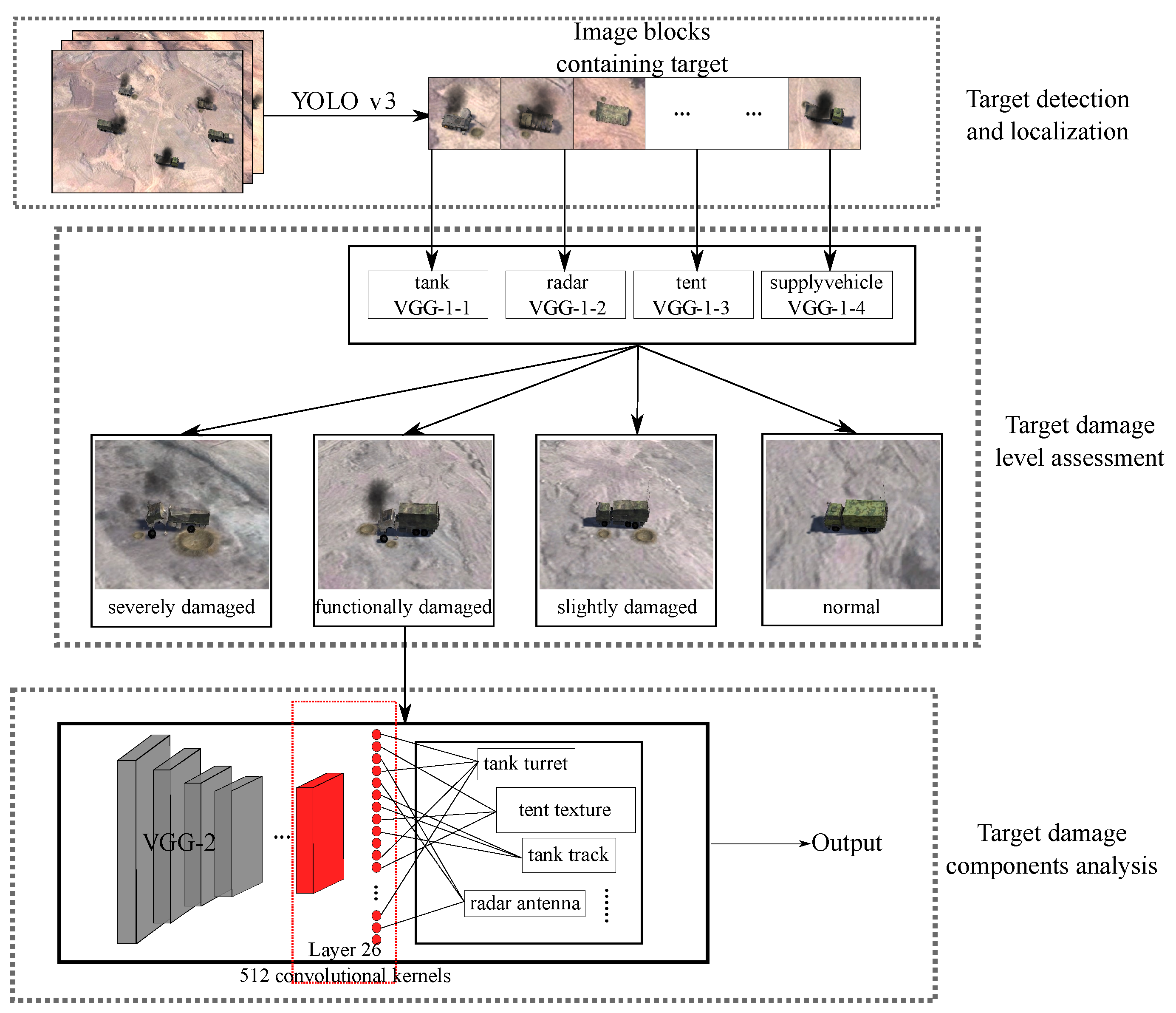
As shown in Figure 1, YOLO-VGGNet consists of three modules. Firstly, the YOLO v3 detects, classifies, and localizes mobile targets in the images. Then, the VGG-1 series networks assess the damage level of detected targets coarsely. Finally, image blocks for functionally damaged targets are fed into the VGG-2 network for further analysis of the targets’ key components.
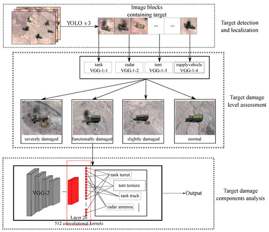
Figure 1.
The process of mobile ground target detection and damage assessment by patrol missiles.
We divide our contributions into two parts. In Section 3, we proposed a two-stage learning-based framework for mobile ground targets based on YOLO prior information, which can meet the requirements of real-time detection and timely damage assessment online. In Section 4, a novel convolutional feature clustering method based on CAM and guided backpropagation of deconvolution was proposed for the first time to evaluate the components of damaged targets.
3.1. Target Detection Based on YOLO v3
Considering the movement of ground targets, the YOLO v3 network is utilized to detect, classify, and localize them online. Compared to YOLO v1 and YOLO v2, YOLO v3 features significant changes in some functions: Multiscale detection logic is introduced to meet the needs of detection for targets of different scales. The concept of multilabel classification is applied to meet the requirements for detecting multiple types of targets. The loss function is optimized to make the prior bounding box more accurate for target positioning. Although YOLO v4, YOLO v5, and other subsequent versions have also emerged more recently, the essential functions needed, such as detection, classification, and localization, have remained unchanged. In addition, YOLO v3 is widely used in engineering, and its stability has been verified. Let G be the input image, then the YOLO v3 network can be described by:
where indicates the YOLO v3 network and is its weights. There are n detected targets in the original image and describes the image block of the mth detected target. It consists of three parts: the parameters of the bounding box , the target’s class , and the target’s confidence . Another critical setting in the training process is the loss function, as shown in (2).
The loss function consists of three parts: the coordinate prediction error , the confidence error , and the classification error . They are built for the location, detection, and classification, respectively. Specifically, the is defined as follows:
where is the weight of the coordinate error, is the number of grids in the input image, and A is the number of bounding boxes generated by each grid. If the ath anchor box of the gth grid is responsible for this target, the value of is 1. Otherwise, the value of is 0. The hat above the parameters is used to distinguish the predicted bounding box from the labeled box, including , , , and as the x-coordinate, y-coordinate, width, and height, respectively. Obviously, the smaller the , the more accurate the prediction.
In our implementation, four types of mobile ground targets, including tanks, radars, supply vehicles, and tents, are selected and a total of 1250 images of them are collected in the simulation system. Note that these images are of different damage levels. Besides, to speed up the training process, the Darknet53 pre-training model is used in the initialization of the YOLO v3 network. In the training process, the epoch of the training dataset is 100, the batch size is 8, and the learning rate is 0.001.
3.2. Target Damage Level Assessment Based on VGG-1
Based on the prior detection, classification, and localization information of targets by YOLO v3, the image block of the mth detected target could be cropped from the image G and then fed into the VGG-1 series networks to assess the target’s damage level. Considering the huge differences among different types of ground targets, four class-specific assessment models are designed for four types of targets. According to the classification of image blocks , the corresponding VGG-1 network is selected: VGG-1-1, VGG-1-2, VGG-1-3, and VGG-1-4 for the tank, radar, supply vehicle, and tent, respectively.
Then, the damage level assessment problem can also be simplified as a classification problem. There are many other classification networks with deeper layers, stronger feature representation capabilities, and higher recognition accuracy than VGG, such as ResNet-18 and Inception v3. However, VGG is a classical serial CNN without a residual structure, which means that the extracted feature map contains the target’s position information. For example, the upper left corner of the feature map strictly corresponds to the upper left corner of the original image. Therefore, by means of weight visualization, CAM can visualize the regions in the feature map that the neural network pays attention to, meaning that the results of VGG are highly interpretable.
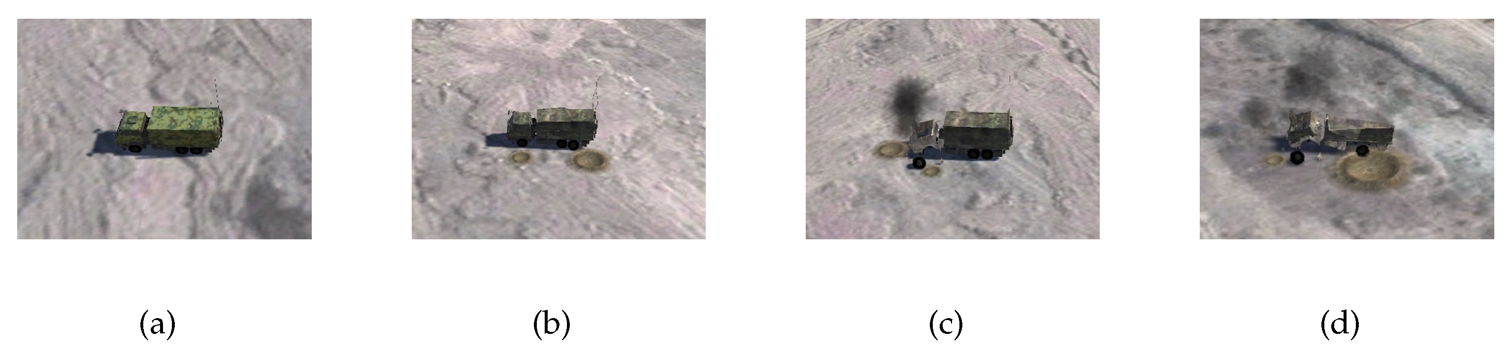
For each types of ground targets, they can be divided into different damage levels. In this work, four types of targets are labeled as four damage levels: normal, slightly damaged, functionally damaged, and severely damaged, as shown in Figure 2. Normal is for the target that has not been struck. Slightly damaged means that the functions of the target are not affected. Functionally damaged targets lose one or more key components. Severely damaged indicates that the target has been totally destroyed and lost all of its key components.
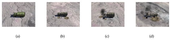
Figure 2.
Supply vehicles with different damage levels. From (a–d), the damage levels of supply vehicles are normal, slightly damaged, functionally damaged, and severely damaged, respectively.
As a classification problem, the loss function only contains the classification error, which is shown in (4).
where y is the image’s label, is the predication of the VGG-1 network, and is the error between the classification and the target label. indicates the loss network of VGG, indicates the number of layers of the network, and indicates the feature map size of layer l. VGG uses the perceptual loss function based on human eye perception, which is different from the earlier loss function based on image pixel space. The loss function does not match the image quality and features perceived by the human eye, while the space calculated by the perceptual loss function is converted from image space to feature space. Such a loss function setting has the advantage of a more understandable feature extraction, which can effectively extract the target’s advanced semantic features and exclude irrelevant factors’ interference. The VGG-1 series networks can be described by:
indicates the VGG-1 network of category and is its weights, is the output of YOLO v3. The output contains four damage levels: normal, slightly damaged, functionally damaged, and severely damaged.
To speed up the learning process and ensure the classification accuracy of the trained model under limited samples, only the parameters of partial layers are updated in the training process, which is usually called fine-tuning. As for the dataset, targets with four different damage levels are collected from the simulation environment. The dataset contains 1000 images with 4 damage levels. For each type of target, 250 images are collected, of which 200 are used as training and validation samples, and 50 are used as test samples. In the training process, the epoch of the training dataset is 20, the batch size is 32, the learning rate is 0.001, and the output of the final fully connected layer is modified to 4.
4. Target Damaged Components Analysis Based on Convolutional Feature Clustering
After evaluating the damage level of the targets in the image blocks, the proposed convolutional feature clustering will be activated to analyze the damaged components for functionally damaged targets, which can cluster convolution kernels with large response values at the target’s specific components. We can judge whether the component is destroyed according to activation intensity of the clustered convolution kernels.
We divide the convolutional feature clustering into three steps. The first is to select the convolutional layer, which contains the richest weight information of the targets’ components. We compared the weight visualization of three CAM methods using ablation experiments and chose the best to visualize the weights of four targets layer by layer. Finally, the 26th convolutional layer in Score-CAM is selected after comparison.
The second is the improvement of deconvolution for clustering the convolution kernels of different types of targets. Deconvolution is used to analyze the feature extracted by convolution kernels. We found that different targets of the same class tend to activate specific convolution kernels due to similar components and structures. Therefore, by the guided backpropagation, we collected the (top 10 activation intensity kernels of the layer) clustered convolution kernels of a certain number of radars, tents, supply vehicles, and tanks. The result shows that different radar targets tend to activate the same part of the convolution kernels because they contain the same characteristics (the radars all contain antenna and bracket).
At last, we deepen the study from different targets to the targets’ different components by guiding the backpropagation of convolution kernels. It is experimentally demonstrated that for different components of the same target, partial convolution kernels exist, which are focused on extracting features of the same component. Therefore, we proposed the novel convolutional feature clustering method, which can cluster the convolution kernels with large response values at the target’s specific components and determine whether that component is destroyed by detecting the sum of the activation intensity of the clustered convolution kernels. Furthermore, we evaluate eight damaged components of four types of targets based on the convolutional feature clustering method and verify the effectiveness of our method.
4.1. Feature Visualization Based on CAM
A total of 1200 images were collected for VGG-2 with four types of targets, of which 1000 were used as training sets and 200 as the test set. In addition, we do not need damaged training data, all belong to “normal”. The training parameters and the loss function are the same as those for the VGG-1 series.
Based on the gradient information, the CAM is backpropagated from the result to the intermediate convolutional layer. Then, the weights of all feature maps in the layer are summed and mapped onto the original image in the form of a heatmap, as shown in (6).
where n is the number of feature maps, is the feature map in the convolutional layer, and is the weight of the feature map when the classification result is c. Global average pooling (GAP) ensures that the number of feature maps matches the weight parameters. From the optimization perspective, this equation can be converted into (7).
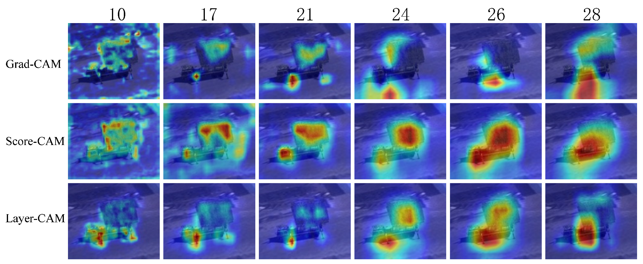
where , and is the weight of the kth neuron of layer l after GAP. The application of the activation function prevents the disappearance of the gradient, but there is still a partial loss. The CAM image is generated by upsampling to scale up to the input image’s size and superimpose it on the original. Three activation mapping visualization methods, Grad-CAM, Score-CAM, and Layer-CAM, were selected to analyze the features extracted from the intermediate VGG convolutional layers. The ablation experiment was performed to compare their feature visualization effect. The radar is taken as an example, as shown in Figure 3.
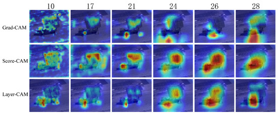
Figure 3.
The comparison of different CAM visualizations.
The low and middle convolutional layers in Grad-CAM have poor feature visualization because of the loss of gradient information when backpropagating. Layer-CAM significantly improves due to a smaller loss of gradient information when backpropagating. Score-CAM gets rid of the dependence on the gradient and the final result is obtained from a linear combination of weights and activation mapping, which best visualizes the features extracted at the targets’ components.
It is concluded that Score-CAM has the best feature visualization of the target’s components. We select the convolutional layer with the richest weight information based on Score-CAM. Moreover, this characteristic corresponds to the VGG’s loss function based on human eye perception. Since the low convolutional layers mainly extract simple and intuitive features, while the middle and high layers are richer in semantic information, the focus is on visualizing the middle and high layers. The feature of the target’s different components can be separated during the processing, and we only visualize the weight information using Score-CAM. As shown in Figure 4, different targets have different weighting components, mainly distributed in tent structures, tank turrets and armor, supply vehicle heads and trunks, and radar brackets and antennas.
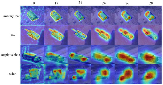
Figure 4.
Score-CAM feature visualization for different targets.
The advantage of feature visualization based on CAM is that the gradient information relying on the convolution process is simple and intuitive, and the weights of the target’s components are comprehensible. The disadvantage is that the presented heat map is the accumulation of the weights of all convolution kernels in this layer. We cannot analyze the convolution kernels with different degrees of activation separately.
4.2. Deconvolution Feature Visualization Analysis
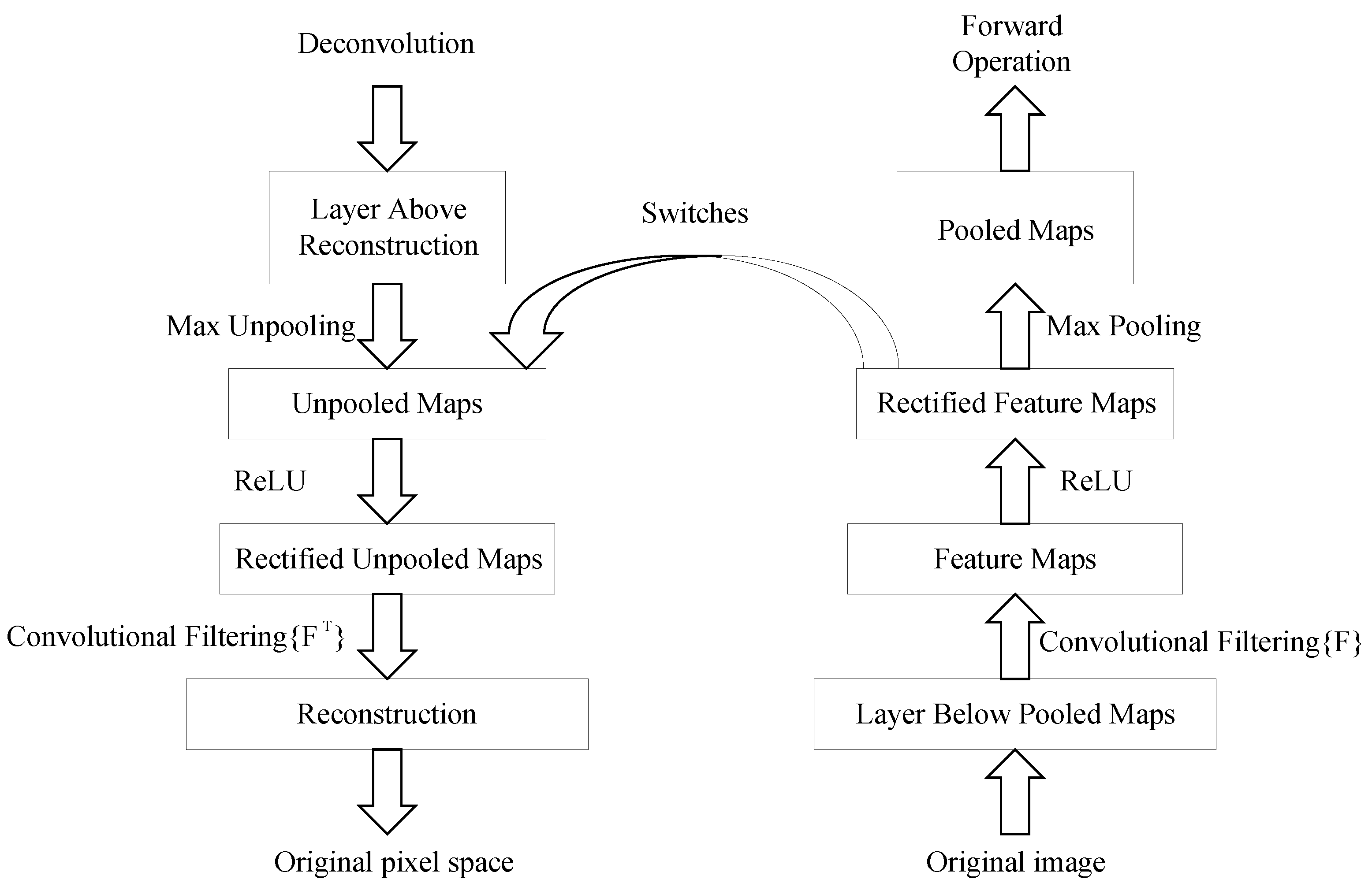
Deconvolution is the reverse operation of convolution. The concept of deconvolution was initially applied in signal processing techniques. Encouraged by its great progress in signal processing, deconvolution has been widely used in various fields. The deconvolution originates from Ref. [30], in which Zeiler et al. firstly visualized the features to enhance the interpretability of convolution kernels. The “deconvolution” in our paper refers to the deconvolution process. It refers to the backpropagation of the features extracted in an intermediate convolutional layer to the original pixel space, which is beneficial for analyzing features extracted by convolution kernels. As shown in Figure 5, no new parameters are learned in the deconvolution process, which is unsupervised.

Figure 5.
Schematic diagram of the deconvolution.
It is well known that neural networks consist of multiple layers, each containing numerous neurons. For example, each CNN layer contains hundreds or thousands of convolution kernels. Different convolution kernels are trained to extract different features of a target. However, for different targets or different target’s components, only a small number of convolution kernels will be activated in response. Deconvolution visualization can establish the connection between the feature map of the intermediate layers and the original image. Although the features extracted by the convolution kernels can be analyzed visually and graphically, no one knows at which layer and by which convolution kernels extract the needed features. Therefore, we propose a new convolutional feature clustering method by combining the advantages of CAM and deconvolution. It first selects the convolutional layer according to the CAM, which contains the richest feature information of the target’s components, and then clusters the convolution kernels with large responses to the target or the target’s specific components by deconvolution.
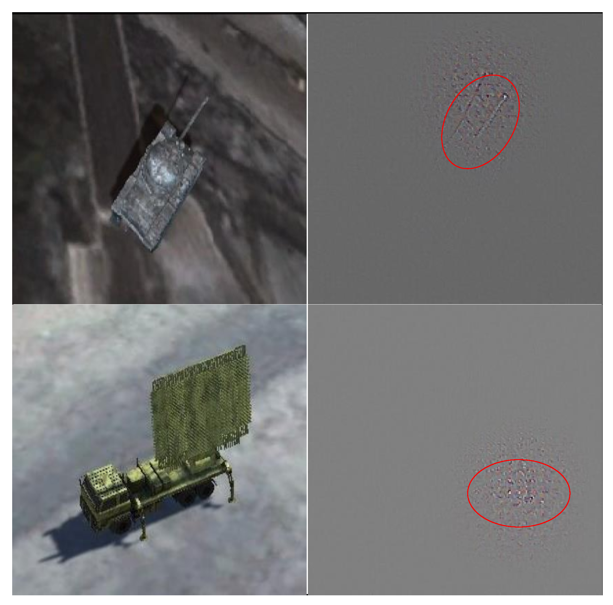
Figure 3 reveals that the features extracted by the 26th layer of convolution have better discrimination of the target’s components. Therefore, we analyzed 512 feature maps of this layer (The size of each feature map is 14 × 14). Herein, we introduce the maximum activation visualization method. It generally finds the maximum activation value in each feature map, then compares the maximum activation values of all feature maps in this layer and selects the largest one as the maximum activation unit. Finally, it sets all parameters in this layer to zero except for the maximum activation unit and maps the maximum activation unit to the original pixel space by deconvolution. The principle is shown in (8).
where indicates the unit in the 26th convolution layer, j indicates the number of feature maps, and i indicates the unit number in each feature map.
As shown in Figure 6, the target’s components corresponding to the maximum activation unit are the tank turret and radar bracket. This method is useful for analyzing the extracted features of the convolution kernels, but it is one-sided. Only comparing the maximum activation values of the feature maps cannot represent the true activation area of the 196 units of each feature map, since the activation values for areas without targets are negative and cannot all be summed up. Considering the proportion of the actual target in the image, we add a filter to remove the noise from irrelevant areas of the image and only keep the areas with large response values. The sum of the first 36 activation units is taken as the activation intensity of this feature map. Meanwhile, different convolution kernels may extract features of the same target or the same target’s component. We convert (7) to (9). The improved maximum activation visualization method is shown in (10). It realizes the feature visualization extracted from any single convolution kernel by deconvolution.
where , is the weight of the kth neuron of layer l after GAP. is the filter, which retains the first 36 activation units in the feature map and sets the other to zero.
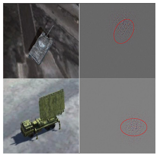
Figure 6.
Maximum activation unit deconvolution visualization.
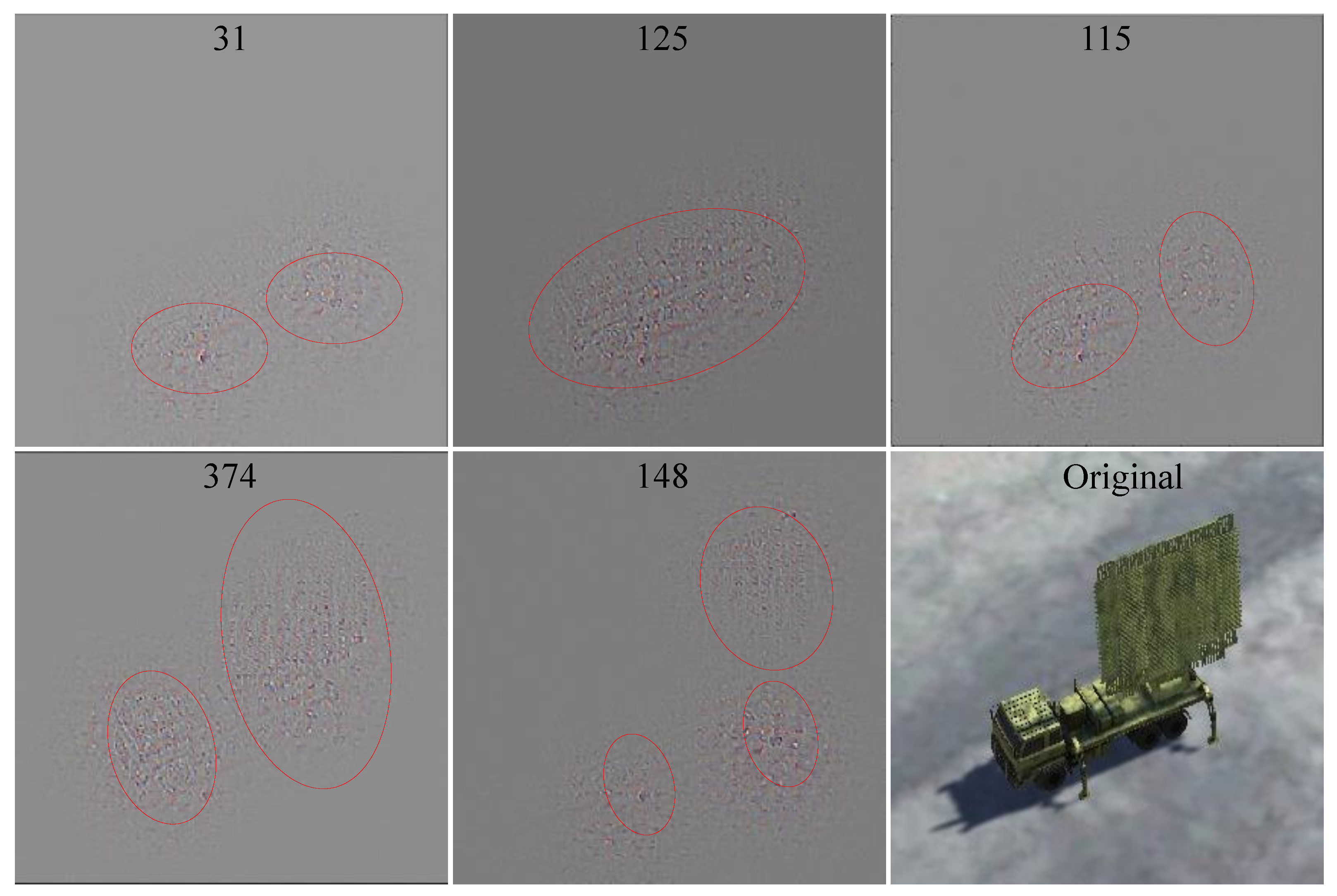
For the radar target, we visualized the feature extracted by the top 10 (when comparing the activation intensity of feature maps, only the sum of the top 36 units are compared) convolution kernels in the 26th layer. Some of the visualized results are shown in Figure 7, where the numbers are the convolution kernel serial numbers, and the central recognition areas are framed by ellipses. Fifty different radar images were tested, and the frequency distribution of the top 10 in 512 convolution kernels is shown in Figure 8. The test results of the tank, tent, and supply vehicle are shown in Table 1.
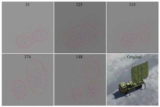
Figure 7.
Deconvolution visualization of clustered convolution kernels for radar target.
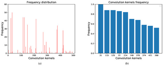
Figure 8.
The frequency distribution of different radar targets. (a) The frequency distribution of 512 convolution kernels. (b) The frequency of clustered convolution kernels.

Table 1.
Activation intensity ranking of feature maps for different types of targets.
Table 1 and Figure 8 reveal that the same type of targets activates almost the same convolution kernels in the high-layer convolution (26th layer) because they contain the same characteristics(radar bracket and antenna). In addition, different types of targets activate different convolution kernels. Therefore, we can conclude that different convolution kernels are trained to extract different features. Several convolution kernels exist that mainly extract features from the target’s specific components.
4.3. Convolutional Feature Clustering for Target-Damaged Components
We can cluster the convolution kernels sensitive to certain types of targets based on deconvolution. However, the following question arises: what about the specific components of the target? Our method is essentially a form of guided backpropagation, in which only the weights of the target’s key components are backpropagated.
4.3.1. Guided Backpropagation for Target-Damaged Components
The radar image is divided into 14 × 14 grids corresponding to 14 × 14 units of the feature map to generate a mask for the radar antenna, as shown in Figure 9. The units in the mask are summed as the activation intensity of the radar antenna component. As shown in (11), the activation intensity of the 512 masks in this layer are sorted to derive the clustered convolution kernels for the radar antenna . The visualization results are shown in Figure 10. Twenty radar images were tested, and the frequency distribution of the radar antenna and bracket is shown in Figure 11. The clustered convolution kernels, for the radar bracket, are . The test results are consistent with the data in Table 1.
where indicates the mask of the radar antenna. Only the units in the mask area are 1, and the rest are 0. is the d-th feature map. is the sum of the masked area units in the d-th feature map. The deconvolution visualization of the target’s components is shown in (12).
where , and K is the clustered convolution kernel vector.
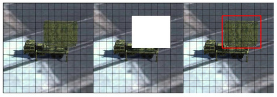
Figure 9.
Radar antenna mask.
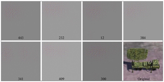
Figure 10.
Visualization of the extracted features by the radar antenna clustered convolution kernels.
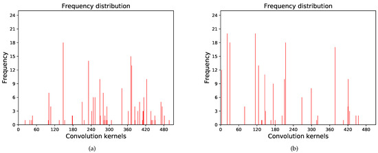
Figure 11.
Frequency distribution of the target’s different components. (a) Radar antenna. (b) Radar bracket.
We also test the degree of feature entanglement between a target’s different components and find that this layer’s feature entanglement is relatively tight. The relevant components can contribute to each other’s activation intensity in the feature extraction process.
4.3.2. Analysis of Damaged Components Based on Convolutional Feature Clustering
We input image blocks of the radar into the VGG-2 network to analyze the damaged components and take the radar bracket and the antenna as an example for testing, as shown in Figure 12.
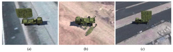
Figure 12.
Sample of damaged components. (a) Damaged bracket. (b) Damaged antenna. (c) Intact.
The principle of convolution feature clustering is shown in (13). The changes in activation intensity of the clustered convolution kernels for radar’s components are shown in Figure 13.
where indicates the VGG-2 network and is its weights. If the result of is functionally damaged, the image block will be input to VGG-2 network. is the sum activation intensity of the clustered convolution kernels. q indicates the different components of the target.
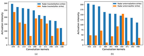
Figure 13.
Changes in the activation intensity of clustered convolution kernels before and after the strike. (a) Radar bracket. (b) Radar antenna.
As shown in Figure 13, the activation intensity of the clustered convolution kernels decreases significantly after the strike. Therefore, we can set a threshold, and the sum of the activation intensity of the clustered convolution kernels can be used as a condition to determine whether the target’s components have been destroyed. The images of the target before and after the strike are shown in Figure 14. The clustered convolution kernels for the targets’ different components are shown in Table 2.
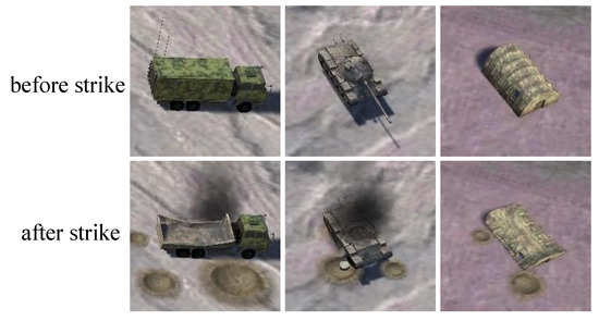
Figure 14.
Image changes before and after the strike.
Table 2.
Clustered convolution kernels for the targets’ different components.
We take the tank turret, the tent structure, and the supply vehicle trunk, as examples. The changes in the activation intensity of the clustered convolution kernels before and after the strike are shown in Figure 15.

Figure 15.
The changes in the activation intensity of the clustered convolution kernels.
5. Experimental Validation and Results
The difficulty of obtaining images of mobile ground targets from high altitudes is well known, and there are few existing datasets for the damage assessment of mobile ground targets. Therefore, we conducted experiments based on a simulation environment.
To simplify our model while making it more applicable to the real world, we added object shadows as well as the strike effects of sparks, craters, and thick smoke on the targets. Furthermore, we introduced environmental noise, interference from ground buildings, and dynamic lighting changes and divided the simulation scenario into two parts: before and after the strike.
5.1. Traditional Damage Assessment Method Based on Image Change Detection
The simulation platform is divided into the server and the client. The server sends the RGB images collected by the missile swarm to the client through the UDP protocol. The flight trajectory of the missile swarm is randomly initialized. Due to the missile swarm mission requirements, we assume that the nodes in the swarm can send image information of the ground targets to each other in real-time and detect the changes before and after the strike.
As we know, image-change-detection-based methods are greatly affected by the surrounding environment. The results of the PCA-k-means are shown in Figure 16, and the states below are the evaluation results. Due to the uncertainty of the image change factors, the smoke and sparks around the target negatively impact the evaluation. In addition, the degree of an image change in the target area is not necessarily related to the target’s damage level, which increases the difficulty of damage assessment based on image change detection.
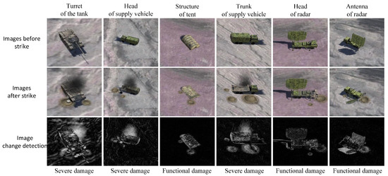
Figure 16.
The result of PCA-k-means assessment.
5.2. Analysis of Experimental Results
As for YOLO-VGGNet, the YOLO v3 detects, classifies, and localizes the targets in the images. To meet the requirements of real-time detection and timely damage assessment, the recognized image blocks containing the target are stored in a memory buffer. At the same time, another process is activated to input the image blocks into the VGG-1 series networks for damage level assessment. If the assessment result is functionally damaged, the image blocks will be further input into the VGG-2 network for damaged components analysis to maximize the use of computing resources. The time consumption for each stage of the YOLO-VGGNet damage assessment is shown in Table 3. The client received 15 frames per second through the UDP protocol in the actual test. Our hardware configuration is a Lenovo y7000p rescuer laptop, RTX2060 GPU, and 32GB memory. The maximum processing speed is 21 frames per second. The corresponding convolutional feature clustering thresholds are set for the target’s different components. Then, the missile swarm detects the ground target in real-time according to the predetermined trajectory, assesses the damage level, and analyzes the damaged components in a timely manner.
Table 3.
Time consumption for each stage of YOLO-VGGNet damage assessment.
In addition to PCA-k-means, we also compared our method with Mask-RCNN-based and Bayesian-Network-based methods on the basis of YOLO’s prior information. The comparison of damage level assessment results is shown in Table 4. The number of targets for each damage level is 250 and the columns show the proportions of correct valuations. The recognition rate of YOLO-VGGNet, PCA-k-means, Mask RCNN, and Bayesian Network are 83.1%, 66.6%, 74.3%, and 67.1%.
Table 4.
The results of the damage level assessment.
The experimental results show that the two-stage learning-based method YOLO-VGGNet achieves higher accuracy than traditional image-change-detection-based and single-stage learning-based methods. Although traditional methods evaluate faster and have a strong generalization ability to scenarios, they mainly focus on the physical and pixel spaces. The presence of thick smoke, sparks, and craters around the target can significantly impact the evaluation results. Moreover, the changes in the surrounding environment are not strictly related to the damage level and may come from previous strikes. In addition, it is concluded that single-stage damage level assessment suffers more from the influence of different inter- and intraclass features. Though the two-CNN learning-based method can extract deep semantic information, different destructive targets may exhibit the same damage characteristics due to the targets’ different structural, functional, and anti-destruction characteristics. For example, sparks are fatal to tents but have little effect on tanks. Therefore, training a specific damage assessment model for each type of target is necessary. By specific-type evaluation models, Our two-stage learning-based method not only has the advantage of extracting deep semantic information but also avoids the influence of different inter- and intraclass features. Furthermore, existing methods can only get a rough functional damage assessment according to the damage level. Our method has a clear advantage over existing methods by focusing on the activation intensity of the clustered convolution kernels to determine whether the target’s components are damaged or not, as shown in Table 5.
Table 5.
The functions of different damage assessment methods.
After the damage level assessment, the functionally damaged targets will be analyzed using convolutional feature clustering. The tank tread and turret, the tent structure and texture, the supply vehicle head and trunk, and the radar antenna and bracket were used as examples for testing. During the continuous multiframe detection, as long as one frame of the target’s component is evaluated as normal, that component is judged as normal. The results of the simulation experiments are shown in Table 6. The columns show the proportions of correct valuations.
Table 6.
The results of the assessment of damaged components based on convolutional feature clustering.
Combining the test results of eight evaluated components, the accuracy of damaged components assessment based on convolutional feature clustering is 72%. Corresponding to the feature visualization in Figure 4, the accuracy of components with high weights in the Score-CAM heatmap is higher. These include radar antennas, radar brackets, tank turrets, tent structures, and supply vehicle trunks. In comparison, the accuracy of tank treads and tent texture is lower because these components with lower weight do not have much influence on the final decision during VGG feature extraction.
Although we added various types of interference to the simulation environment, the synthetic images nevertheless differ from authentic images. Therefore, we additionally collected authentic images from the Internet to preliminarily verify the effectiveness of our feature extraction method. Further research with authentic images will be conducted in the future.
6. Conclusions
This paper proposes a damage assessment method based on YOLO-VGGNet for mobile ground targets. Unlike traditional image change detection methods, which require images before and after the strike for comparison, the proposed method learns the target model through extensive training and can assess the target’s damage status based on only online perception. Specifically, with YOLOv3 as the pre-processor, the proposed method can detect, classify, and localize ground targets accurately and quickly. Then, the image blocks of detected targets are fed into the lightweight VGG networks, which can evaluate their damage level. Meanwhile, based on CAM and deconvolution, we further analyze the activation intensity of clustered convolution kernels. On the one hand, it is helpful to determine whether the targets’ key components are destroyed. On the other hand, it provides a more interpretable perspective for learning-based methods. Finally, Unity simulation experiments prove the proposed method’s effectiveness, which improves the accuracy of damage level assessment by 16.0% and 8.8% compared with traditional image-change-detection-based methods and the two-CNN learning-based method. The convolutional feature clustering method evaluates the status of the targets’ key components with an accuracy of 72%.
This work also has some limitations. Firstly, the recognition and localization errors of the targets may increase with the decrease in the angle of view. Further research on multiangle fusion of convolutional feature clustering may be a significant research interest. Secondly, although the proposed method can be utilized to assess the damage to any target’s component, this work focuses mainly on the key components of targets, and the assessment accuracy of components with low weights is lower than those with high weights. In subsequent work, we will attempt to extract more detailed information on the damaged target components and explore information fusion from multiple perspectives to make our method more robust for ground interference.
Author Contributions
Conceptualization, Y.X.; data curation, Y.X.; formal analysis, Y.X. and Q.Y.; investigation, Y.X.; methodology, Y.X., Q.Y. and H.L.; project administration, H.L. and J.X.; resources, H.L.; software, Y.X.; supervision, Z.Z., J.X. and H.L.; validation, Z.Z., J.X., Y.W. and H.L.; writing—original draft, Y.X.; writing—review and editing, Q.Y., Y.W., J.X. and H.L. All authors have read and agreed to the published version of the manuscript.
Funding
This research received no external funding.
Institutional Review Board Statement
Not applicable.
Informed Consent Statement
Not applicable.
Data Availability Statement
All data generated or analyzed during this study are included in this paper or are available from the corresponding authors on reasonable request.
Conflicts of Interest
The authors declare no conflict of interest.
References
- Rauch, J.T., Jr. Assessing Airpower’s Effects: Capabilities and Limitations of Real-Time Battle Damage Assessment; Air Univ Maxwell Afb Al School of Advanced Airpower Studies: Montgomery, AL, USA, 2002. [Google Scholar]
- Tu, Z.; Lin, T. Research on Battle Damage Assessment System Based on Downward-looking Scene Image. Tactical Missile Technol. 2012, 5, 6–9. [Google Scholar]
- Akkouche, K.; Hannachi, N.E.; Hamizi, M.; Khelil, N.; Djouzi, K.; Daoui, M. Knowledge-based system for damage assessment after earthquake: Algerian buildings case. Asian J. Civ. Eng. 2019, 20, 769–784. [Google Scholar] [CrossRef]
- Huang, Y.; Li, H.; Ji, W. Target Damage Rank Assessment Based on Dynamic Bayesian Network. In Proceedings of the 2010 Chinese Control and Decision Conference, Xuzhou, China, 26–28 May 2010; pp. 3644–3649. [Google Scholar]
- Xu, M.; Li, J.; Wang, S.; Hao, H.; Tian, H.; Han, J. Structural damage detection by integrating robust PCA and classical PCA for handling environmental variations and imperfect measurement data. Adv. Struct. Eng. 2022, 25, 13694332221079090. [Google Scholar] [CrossRef]
- Presa-Reyes, M.; Chen, S. Assessing building damage by learning the deep feature correspondence of before and after aerial images. In Proceedings of the 2020 IEEE Conference on Multimedia Information Processing and Retrieval (MIPR), Shenzhen, China, 6–8 August 2020; pp. 43–48. [Google Scholar]
- Ma, X.; Ding, P.; Yan, W. Warship-damage assessment based on Bayesian networks. Ordnance Ind. Autom. 2016, 35, 72–75. [Google Scholar]
- Cheng, H.; Liu, J.; Zhao, J. Assessment of Function Damage Effect to Vehicle Based on Bayesian Network. Ship Electron. Eng. 2015, 35, 58–61. [Google Scholar]
- Yang, K. Method of Battle Damage Assessment with Damage Time Stream. Ship Electron. Eng. 2022, 42, 129–134, 170. [Google Scholar]
- Kuncheva, L.I.; Faithfull, W.J. PCA Feature Extraction for Change Detection in Multidimensional Unlabeled Data. IEEE Trans. Neural Netw. Learn. Syst. 2014, 25, 69–80. [Google Scholar] [CrossRef]
- Li, Q.; Gong, L.; Zhang, J. A correlation change detection method integrating PCA and multi-texture features of SAR image for building damage detection(Review). Eur. J. Remote Sens. 2019, 52, 435–447. [Google Scholar] [CrossRef]
- Wu, C.; Chen, H.; Du, B.; Zhang, L. Unsupervised Change Detection in Multitemporal VHR Images Based on Deep Kernel PCA Convolutional Mapping Network. IEEE Trans. Cybern. 2021, 1–15. [Google Scholar] [CrossRef]
- Yousif, O.; Ban, Y. Improving urban change detection from multitemporal SAR images using PCA-NLM. IEEE Trans. Geosci. Remote Sens. 2013, 51, 2032–2041. [Google Scholar] [CrossRef]
- Wouters, L.; Couasnon, A.; De Ruiter, M.C.; Van Den Homberg, M.J.; Teklesadik, A.; De Moel, H. Improving flood damage assessments in data-scarce areas by retrieval of building characteristics through UAV image segmentation and machine learning—A case study of the 2019 floods in southern Malawi. Nat. Hazards Earth Syst. Sci. 2021, 21, 3199–3218. [Google Scholar] [CrossRef]
- Liu, C.; Sui, H.; Wang, J.; Ni, Z.; Ge, L. Real-Time Ground-Level Building Damage Detection Based on Lightweight and Accurate YOLOv5 Using Terrestrial Images. Remote Sens. 2022, 14, 2763. [Google Scholar] [CrossRef]
- Anastasopoulos, I.; Anastasopoulos, P.C.; Agalianos, A.; Sakellariadis, L. Simple method for real-time seismic damage assessment of bridges. Soil Dyn. Earthq. Eng. 2015, 78, 201–212. [Google Scholar] [CrossRef]
- He, K.; Zhang, X.; Ren, S.; Sun, J. Deep residual learning for image recognition. In Proceedings of the IEEE Conference on Computer Vision and Pattern Recognition, Las Vegas, NV, USA, 27–30 June 2016; pp. 770–778. [Google Scholar]
- Yu, L.; Li, Y.; Zhao, Y.; Bao, B. Assessment of Aircraft Anti Damage Capability Based on BP Neural Network. J. Proj. Rocket. Missiles Guid. 2018, 38, 23–26. [Google Scholar]
- Zhang, Z.; Zhang, L.; Xie, C.; Zhang, B.; Yang, B. Battle Damage Effect Assessment Based on Improved GA-BP Neural Network. FIre Control. Command. Control. 2021, 46, 43–48. [Google Scholar]
- Shen, Y.; Zhu, S.; Yang, T.; Chen, C.; Pan, D.; Chen, J.; Xiao, L.; Du, Q. Bdanet: Multiscale convolutional neural network with cross-directional attention for building damage assessment from satellite images. IEEE Trans. Geosci. Remote Sens. 2021, 60, 1–14. [Google Scholar] [CrossRef]
- Zhang, H.; Wu, Z.; Qiu, Y.; Zhai, X.; Wang, Z.; Xu, P.; Liu, Z.; Li, X.; Jiang, N. A New Road Damage Detection Baseline with Attention Learning. Appl. Sci. 2022, 12, 7594. [Google Scholar] [CrossRef]
- Kumar, S.S.; Devaki, K. Assessing car damage using mask R-CNN. Int. J. Eng. Adv. Technol. 2020, 9, 2249–8958. [Google Scholar]
- Calton, L.; Wei, Z. Using Artificial Neural Network Models to Assess Hurricane Damage through Transfer Learning. Appl. Sci. 2022, 12, 1466. [Google Scholar] [CrossRef]
- Alqahtani, H.; Ray, A. Neural network-based automated assessment of fatigue damage in mechanical structures. Machines 2020, 8, 85. [Google Scholar] [CrossRef]
- Xu, J.; Zeng, F.; Liu, W.; Takahashi, T. Damage Detection and Level Classification of Roof Damage after Typhoon Faxai Based on Aerial Photos and Deep Learning. Appl. Sci. 2022, 12, 4912. [Google Scholar] [CrossRef]
- Tang, S.; Chen, Z. Understanding Natural Disaster Scenes from Mobile Images Using Deep Learning. Appl. Sci. 2021, 11, 3952. [Google Scholar] [CrossRef]
- Xie, L.; Stol, K.; Xu, W. A historical perspective of explainable Artificial Intelligence. Wiley Interdiscip. Rev. Data Min. Knowl. Discov. 2021, 11, e1391. [Google Scholar]
- Zeiler, M.D.; Fergus, R. Visualizing and understanding convolutional networks. European Conference on Computer Vision, Zurich, Swizerland, 5–12 September 2014; pp. 818–833. [Google Scholar]
- Hussain, L.; Ali, A.; Rathore, S.; Saeed, S.; Idris, A.; Usman, M.U.; Iftikhar, M.A.; Suh, D.Y. Applying bayesian network approach to determine the association between morphological features extracted from prostate cancer images. IEEE Access 2018, 7, 1586–1601. [Google Scholar] [CrossRef]
- Zeiler, M.D.; Taylor, G.W.; Fergus, R. Adaptive deconvolutional networks for mid and high level feature learning. In Proceedings of the 2011 International Conference on Computer Vision, Barcelona, Spain, 6–13 November 2011; pp. 2018–2025. [Google Scholar]
- Zhou, B.; Khosla, A.; Lapedriza, A.; Oliva, A.; Torralba, A. Learning deep features for discriminative localization. In Proceedings of the IEEE Conference on Computer Vision and Pattern Recognition, Las Vegas, NV, USA, 27–30 June 2016; pp. 2921–2929. [Google Scholar]
- Wu, W.; Pan, Y. Feature Understanding Based on Deconvolution Visualization. In 3D Imaging Technologies—Multidimensional Signal Processing and Deep Learning; Springer: Singapore, 2021; pp. 51–59. [Google Scholar]
- Selvaraju, R.R.; Cogswell, M.; Das, A.; Vedantam, R.; Parikh, D.; Batra, D. Grad-cam: Visual explanations from deep networks via gradient-based localization. In Proceedings of the IEEE International Conference on Computer Vision, Venice, Italy, 22–29 October 2017; pp. 618–626. [Google Scholar]
- Banerjee, S.; Ghosh, A.; Sorkhel, K.; Roy, T. Post Cyclone Damage Assessment Using CNN Based Transfer Learning and Grad-CAM. In Proceedings of the 2021 IEEE Pune Section International Conference (PuneCon), Pune, India, 16–19 December 2021; pp. 1–7. [Google Scholar]
- Chen, T.Y. Interpretability in convolutional neural networks for building damage classification in satellite imagery. arXiv 2022, arXiv:2201.10523. [Google Scholar]
- Zhang, Y.; Weng, Y.; Lund, J.H. Applications of Explainable Artificial Intelligence in Diagnosis and Surgery. Diagnostics 2022, 12, 237. [Google Scholar] [CrossRef]
- Matin, S.S.; Pradhan, B. Earthquake-induced building-damage mapping using Explainable AI (XAI). Sensors 2021, 21, 4489. [Google Scholar] [CrossRef]
- Jiang, P.; Zhang, W.; Hou, Q.; Cheng, M.; Wei, Y. Layercam: Exploring hierarchical class activation maps for localization. IEEE Trans. Image Process. 2021, 30, 5875–5888. [Google Scholar] [CrossRef]
- Wang, H.; Wang, Z.; Du, M.; Yang, F.; Zhang, Z.; Ding, S.; Mardziel, P.; Hu, X. Score-CAM: Score-weighted visual explanations for convolutional neural networks. In Proceedings of the IEEE/CVF Conference on Computer Vision and Pattern Recognition Workshops, Seattle, WA, USA, 13–19 June 2020; pp. 24–25. [Google Scholar]


Publisher’s Note: MDPI stays neutral with regard to jurisdictional claims in published maps and institutional affiliations. |
© 2022 by the authors. Licensee MDPI, Basel, Switzerland. This article is an open access article distributed under the terms and conditions of the Creative Commons Attribution (CC BY) license (https://creativecommons.org/licenses/by/4.0/).