
A Finite Element Analysis of Tunnel Lining Demolition by Blasting for Subway Tunnel Expansion

Abstract
:1. Introduction
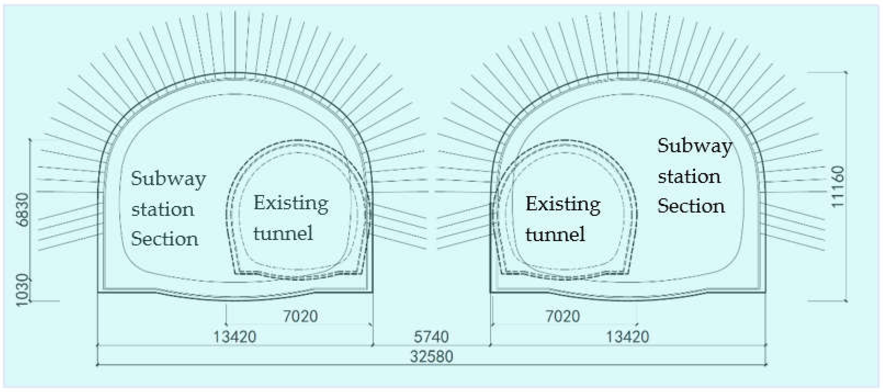
2. Project Profile
3. Parameter Design of Blasting Expansion
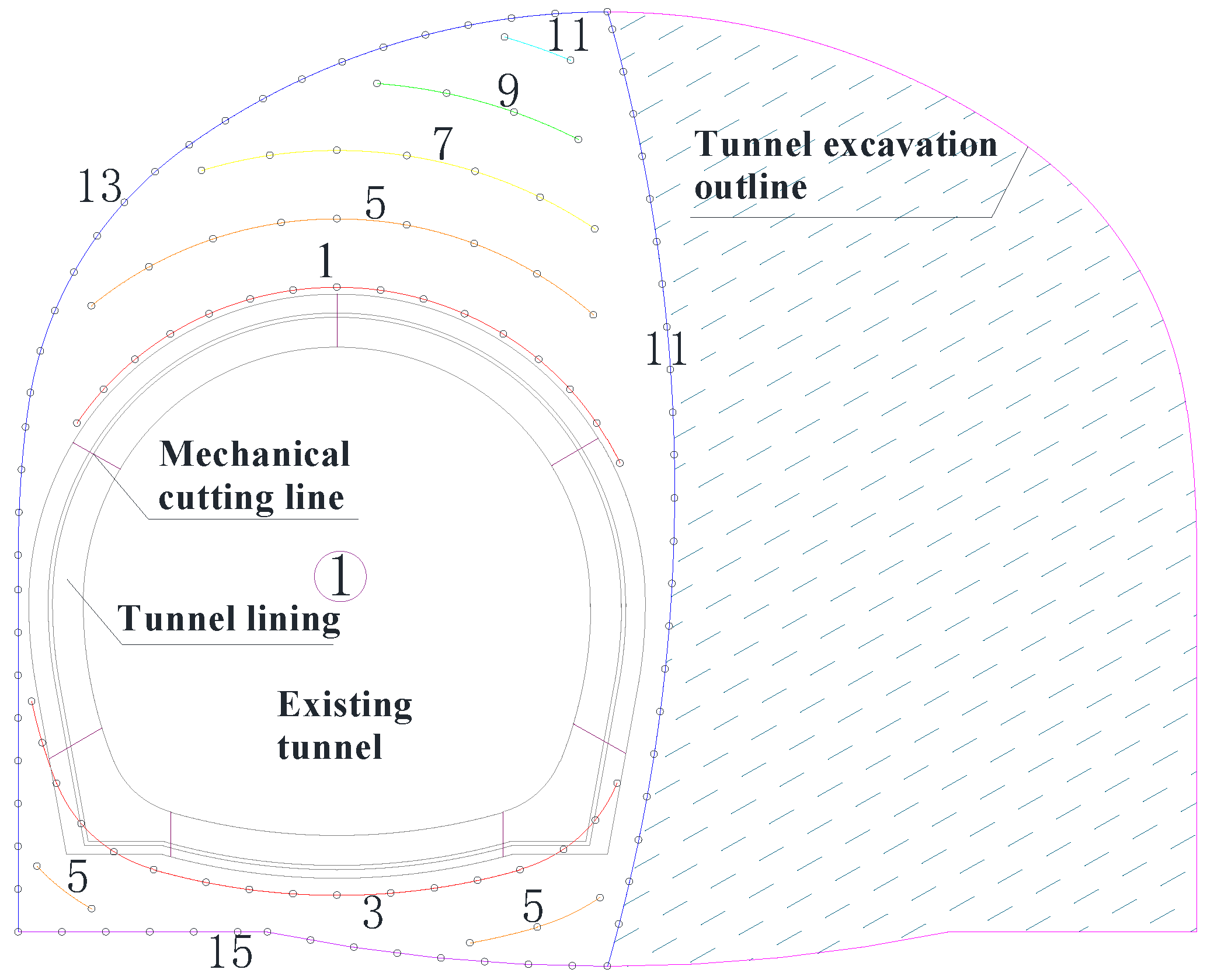
- (1)
- Cut the existing subway tunnel lining, and the average spacing of the longitudinal and circular cutting joints is 3 m and 1.5 m, respectively.
- (2)
- Expand the excavation of the left drift heading of the station section using the drilling and blasting method, and support the excavated left drift heading using an anchor and shotcrete.
- (3)
- Expand the excavation of the right drift heading of the station section using the drilling and blasting method, and support the excavated right drift heading using an anchor and shotcrete.
- (4)
- Excavate and support the inverted arch.
- (5)
- Build the tunnel lining structure of the platform section after the expansion excavation process.
4. Blasting Mechanical Characteristics
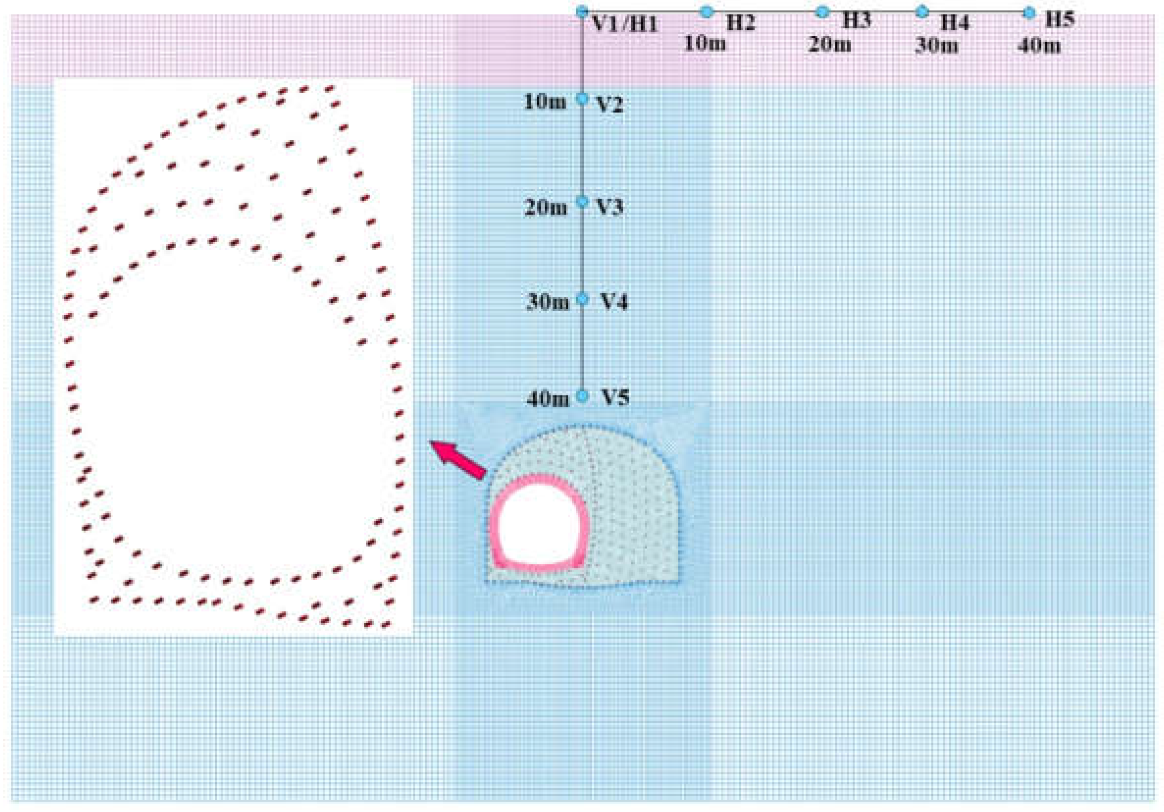
4.1. Numerical Calculation Model and Parameters
4.2. Results Analysis
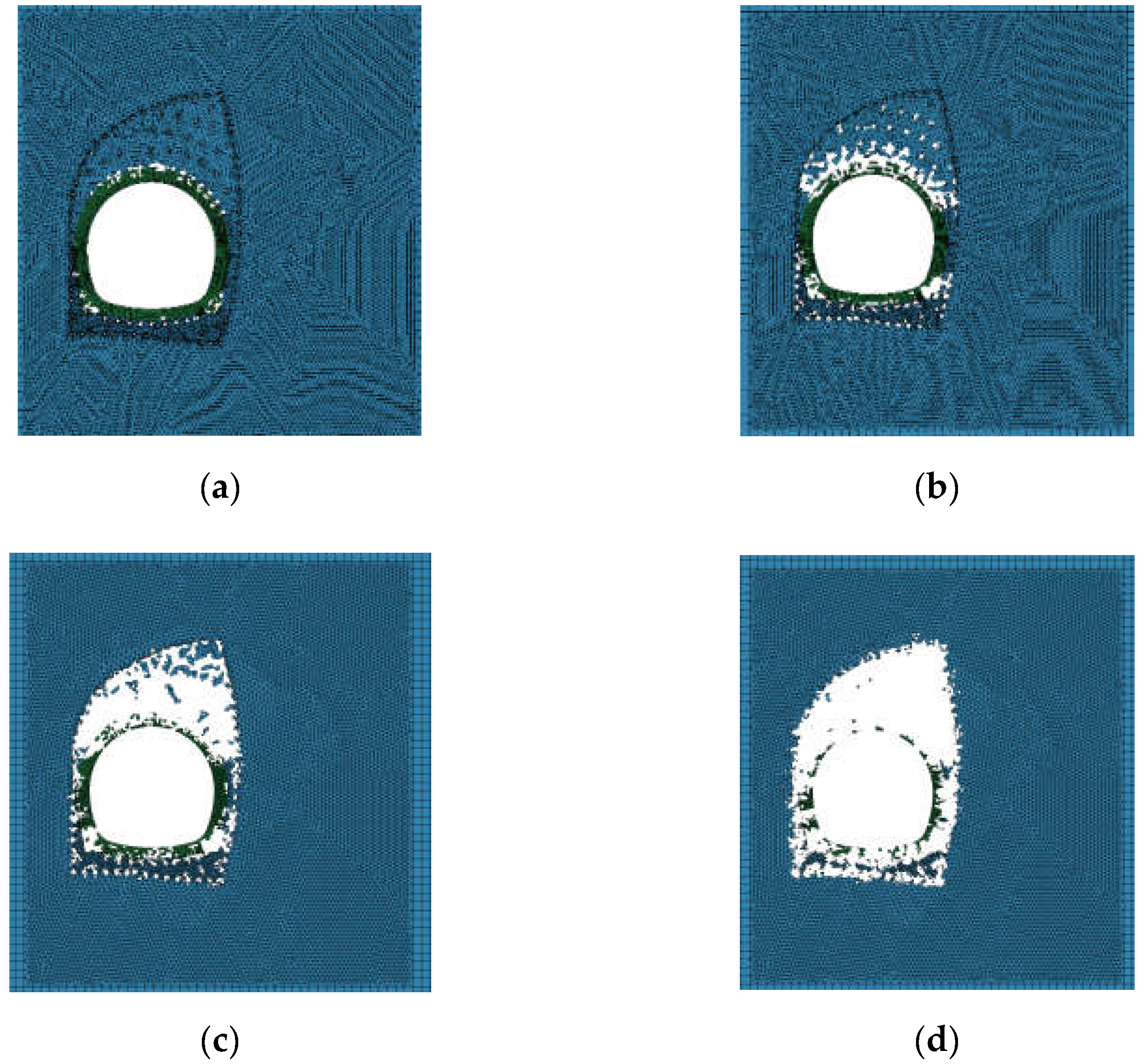
4.2.1. Blasting Quality Analysis
4.2.2. Failure Mechanism of the Vault of Tunnel Lining
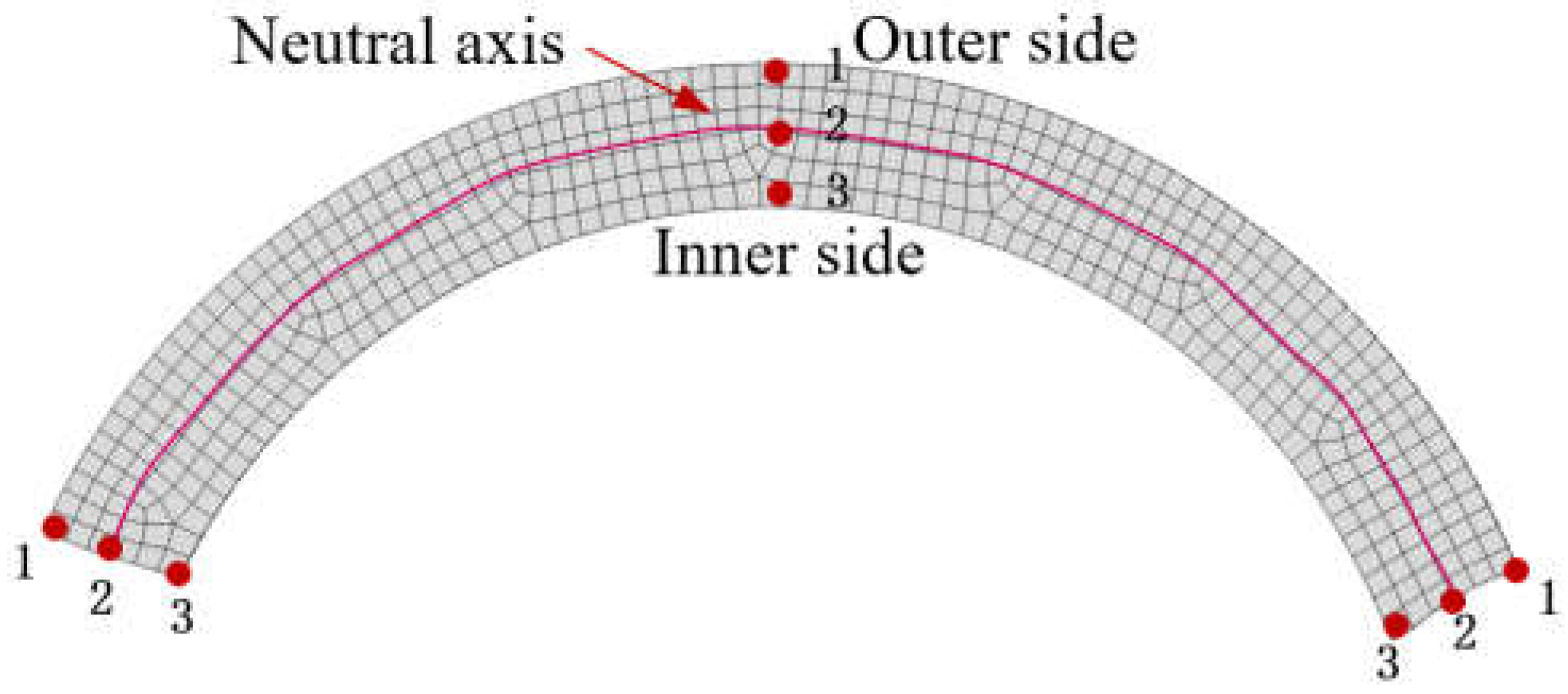
- (1)
- Stress analysis of neutral axis of tunnel lining
- (2)
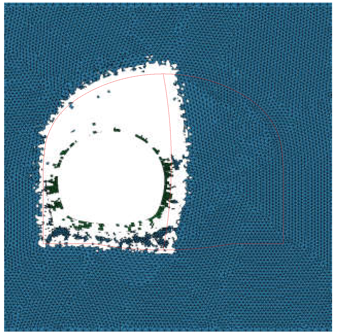
- Radius of blasting fracture zone
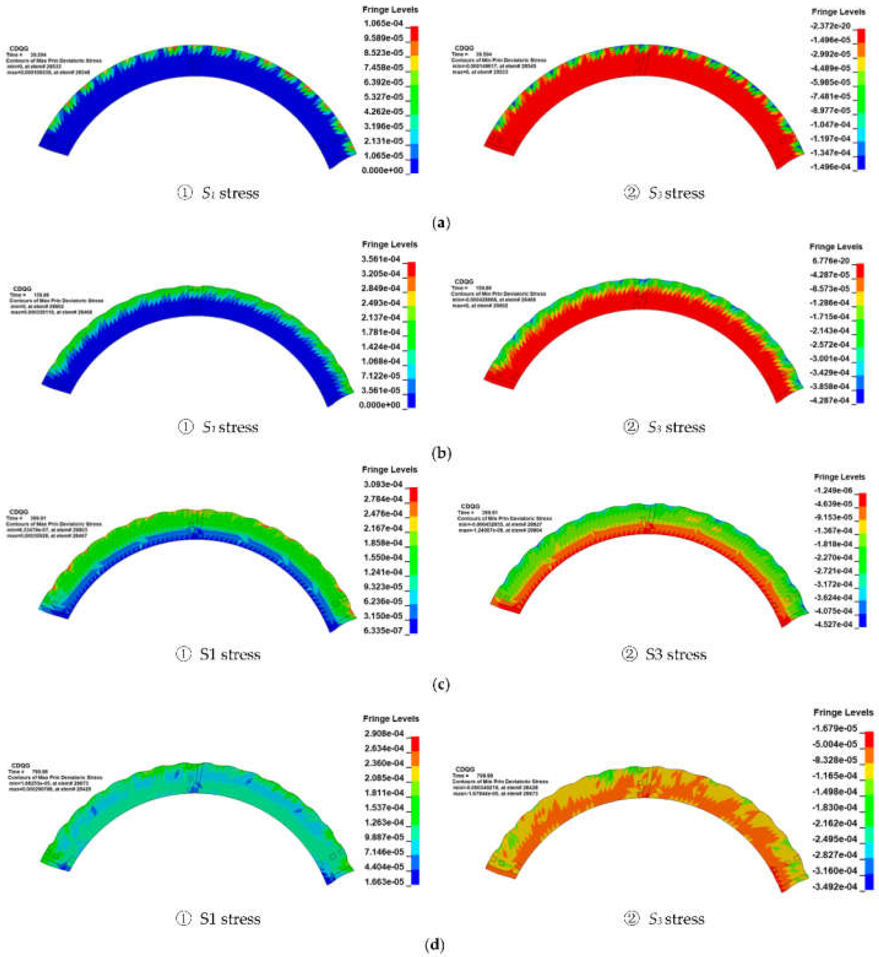
4.2.3. Stress Analysis of Surrounding Rock
4.2.4. Vibration Velocity Analysis
5. Conclusions and Discussion
- Using the blasting parameters proposed in this paper to in situ expansion excavate an existing subway tunnel to a subway station, the maximum overbreak of the tunnel vault, side wall, and inverted arch are 15 cm, 7 cm, and 5 cm, respectively, meeting the requirements of tunnel overbreak and underbreak quality.
- The blasting tensile stress is greater than the tensile strength of the concrete material, and the radius of the blasting fracture zone is 0.93 m, which is greater than the thickness of the tunnel lining, so penetrating cracks occur in the tunnel lining. Therefore, the existing subway tunnel lining will collapse under the action of the blasting wave load and the gravity of the surrounding rock, which makes it possible to quickly demolish the tunnel lining.
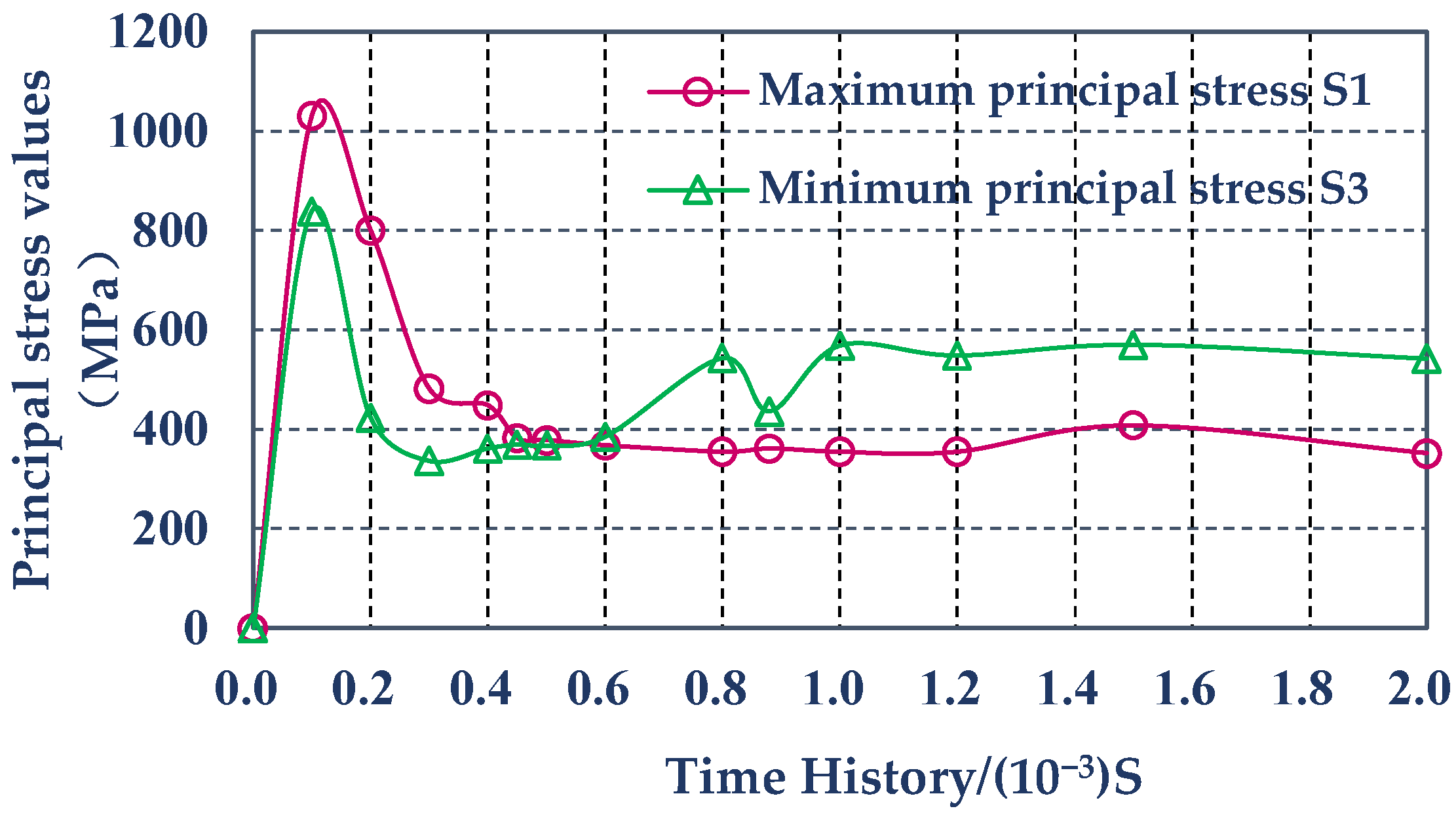
- The maximum principal stress S1 and the minimum principal stress S3 produced by the blasting reach the limit values of the surrounding rock, with the S1 stress being 1030 MPa and the S3 stress being 886 MPa from the initiation of the explosion to the time of 0.1 × 10⁻³ s. The surrounding rock is damaged by the action of the blasting stress. The S1 stress and the S3 stress gradually decrease from the time of 0.1 × 10⁻³ s to 0.4 × 10⁻³ s. The S1 stress tends to be stable; the S3 stress increases and the value is greater than that of S1 until the time of 0.5 × 10⁻³ s. Lastly, the S3 stress tends to be stable at the time of 0.8 × 10⁻³ s.
- The PPVs decrease with the increase in the distance from the blasting center. The relationships between the PPVs and the vertical distance H and the horizontal distance L of the explosion center are as follows: and . Under the condition of the same stratum and charge quantity, the PPVs at different positions from the blasting center can be predicted using Equations (4) and (5) so as to provide a theoretical and design basis for the in situ expansion of tunnel blasting.
Author Contributions
Funding
Institutional Review Board Statement
Informed Consent Statement
Data Availability Statement
Conflicts of Interest
References
- Liu, X.R.; Sun, H.; Chen, X.J.; Huang, Y.S. Numerical analysis on mid-partition structure of the loess double arch tunnel. Chin. J. Undergr. Space Eng. 2005, 5, 837–840. [Google Scholar]
- Yang, J.H.; Jiang, Q.H.; Zhang, Q.B.; Zhao, J. Dynamic stress adjustment and rock damage during blasting excavation in a deep-buried circular tunnel. Tunn. Undergr. Space Technol. 2018, 71, 591–604. [Google Scholar] [CrossRef]
- Xu, X.Z.; Li, Z.P.; Wang, K.; He, H.F. Structural Scheme of Metro Station Constructed by Enlarging Large Diameter Shield Tunnel and Stress and Deformation of Its Key Joints. Chin. R. Sci. 2021, 42, 66–76. [Google Scholar]
- Amiri, H.S.; Murthy, V.M.S.R. Optimising blast pulls and controlling blast-induced excavation damage zone in tunnelling through varied rock classes. Tunn. Undergr. Space Technol. 2019, 85, 307–318. [Google Scholar]
- Zhang, B.; Zhou, Y.F.; Zhang, X.F.; Zhang, Z.Y.; Wang, Z.J.; Wu, Y. Mechanism and Application of Blasting Technology Using Phase-Difference Vibration Mitigation on Adjacent Railway Tunnel. Shock. Vib. 2022. [Google Scholar] [CrossRef]
- Li, M.; Zhu, Z.; Liu, R.; Liu, B.; Zhou, L.; Dong, Y.Q. Study of the effect of empty holes on propagating cracks under blasting loads. Int. J. Rock Mech. Min. Sci. 2018, 103, 186–194. [Google Scholar] [CrossRef]
- Guo, D.M.; Liu, K.; Zhang, W.; Yang, J.; Fan, L.F.; Xue, L. Study on Tunnel Failure Law and Dynamic Response under Different Spacing Adjacent Blast loads. J. Beijing Inst. Technol. 2018, 38, 1000–1005. [Google Scholar]
- Zhou, L.; Zhu, Z.M.; Wang, M.; Ying, P.; Dong, Y.Q. Dynamic propagation behavior of cracks emanating from tunnel edges under impact loads. Soil Dyn. Earthq. Eng. 2018, 105, 119–126. [Google Scholar] [CrossRef]
- Kumar, R.; Choudhury, D.; Bhargava, K. Determination of blast-induced ground vibration equations for rocks using mechanical and geological properties. J. Rock Mech. Geotech. Eng. 2016, 8, 341–349. [Google Scholar] [CrossRef]
- Deng, E.; Yang, W.; Zhang, P. Analysis of Surrounding Rock Vibration and the Influence of Soft Rock Mechanical Parameters During the Tunnel Blasting with Thin Bedrock Roof. Geotech. Geol. Eng. 2020, 38, 537–550. [Google Scholar] [CrossRef]
- Iwano, K.; Hashiba, K.; Nagae, J.; Fukui, K. Reduction of tunnel blasting induced ground vibrations using advanced electronic detonators. Tunn. Undergr. Space Technol. 2020, 105, 1–10. [Google Scholar] [CrossRef]
- Song, X.L.; Gao, W.W.; Ji, J.M.; Ye, M.B.; Zhang, D.J. The Effect of Blasting Vibration on the Cumulative Damage Effect of Tunnel Surrounding Rock. Vib. Shock. 2020, 39, 54–62. [Google Scholar]
- Zhou, J.R.; Lu, W.B.; Zhang, L.; Chen, M.; Yan, P. Attenuation of Vibration Frequency during Propagation of Blasting Seismic Wave. Chin. J. Rock Mech. Eng. 2014, 33, 2171–2178. [Google Scholar]
- He, C.L.; Yang, J. Experimental and numerical investigations of dynamic failure process in rock under blast loading. Tunn. Undergr. Space Technol. 2019, 83, 552–564. [Google Scholar] [CrossRef]
- Tang, X.X.; Xia, D.D.; Li, D.H.; Wang, Y.W. Analysis of the Influence of Tunnel Blasting Construction on Initial Concrete. J. Rai. Eng. Soc. 2022, 39, 73–78+113. [Google Scholar]
- Ji, L.; Zhou, C.B.; Zhang, B.; Wang, F.X. Study on Dynamic Response and Damage Effect of Surrounding Rock in Large Tunnel under Blasting Excavation. J. Chin. Rai. Soc. 2021, 43, 161–168. [Google Scholar]
- Liu, D.; Gao, W.; Sun, B.P.; Liu, D.H.; Zhou, S.S. Numerical simulation study on blasting vibration of existing tunnel expansion. Rock Soil Mech. 2016, 37, 3011–3016. [Google Scholar]
- Zhao, H.B.; Long, Y.; Li, X.H.; Lu, L. Experimental and numerical investigation of the effect of blast-induced vibration from adjacent tunnel on existing tunnel. KSCE J. Civ. Eng. 2016, 20, 431–439. [Google Scholar] [CrossRef]
- Zhang, Z.; Zhou, C.B.; Alex, R.; Wu, T.G.; Xia, Y.Q. Dynamic response and safety control of civil air defense tunnel under excavation blasting of subway tunnel. Tunn. Undergr. Space Technol. 2021, 112, 103879. [Google Scholar] [CrossRef]
- Luo, S.; Yan, P.; Lu, W.B.; Chen, M.; Wang, G.H. Research on the simulation of blasting damage and its mechanism of deep tunnel excavation. Chin. J. Rock Mech. Eng. 2021, 40, 2760–2772. [Google Scholar]
- Luo, S.; Yan, P.; Lu, W.B.; Chen, M.; Wang, G.H.; Lu, A.; Liu, X. Effects of In-situ Stress on Blasting Damage during Deep Tunnel Excavation. Arab. J. Sci. Eng. 2021, 46, 11447–11458. [Google Scholar] [CrossRef]
- Wang, C.; Liu, Z.; Gao, L.; Xu, D.; Zhuang, Z. Analytical and numerical modeling on resonant response of particles in polymer matrix under blast wave. Comp. Mater. Sci. 2017, 140, 70–81. [Google Scholar] [CrossRef]
- Lak, M.; Marji, M.F.; Bafghi, A.Y.; Abdollahipour, A. A Coupled Finite Difference-Boundary Element Method for modeling the propagation of explosion-induced radial cracks around a wellbore. J. Nat. Gas Sci. Eng. 2019, 64, 41–51. [Google Scholar] [CrossRef]
- Liang, Z.Z.; Gong, B.; Li, W.R. Instability analysis of a deep tunnel under triaxial loads using a three-dimensional numerical method with strength reduction method. Tunn. Undergr. Space Technol. 2019, 86, 51–62. [Google Scholar] [CrossRef]
- GB/T 50299-2018; Standard for Construction Quality Acceptance of Metro Engineering. China Architecture and Architecture Press: Beijing, China, 2018.
- Figuli, L.; Cekerevac, D.; Bedon, C.; Leitner, B. Numerical analysis of the blast wave propagation due to various explosive charges. Adv. Civ. Eng. 2020, 2020, 8871412. [Google Scholar] [CrossRef]
- Resende, R.; Lamas, L.; Lemos, J.; Calçada, R. Stress wave propagation test and numerical modelling of an underground complex. Int. J. Rock Mech. Min. Sci. 2014, 72, 26–36. [Google Scholar] [CrossRef]
- Xue, F.; Xia, C.C.; Li, G.L.; Jin, B.C.; He, Y.W.; Fu, Y.P. Safety Threshold Determination for Blasting Vibration of the Lining in Existing Tunnels under Adjacent Tunnel Blasting. Adv. Civ. Eng. 2019, 3, 8303420. [Google Scholar] [CrossRef]


| Expansion Method | Maximum Control PPV V/cm·s−1 | K | α | Distance between Blasting Center and Control Particle R/m | Charge Quantity of Each Cycling Blasting Q/kg |
|---|---|---|---|---|---|
| The CD excavation method | 5.0 | 250 | 1.5 | 40 | 25.6 |
| Hole Category | The Segments of Detonator(s) | Number of Holes | Charge Collection (kg/m) | Charge Quantity Per Hole (kg) | Dosage Per Dose (kg) |
|---|---|---|---|---|---|
| Relief holes | 1 | 16 | 0.67 | 1 | 16.0 |
| 3 | 17 | 0.67 | 1 | 17.0 | |
| 5 | 14 | 0.33 | 0.5 | 7.0 | |
| 7 | 7 | 0.33 | 0.5 | 3.5 | |
| 9 | 4 | 0.33 | 0.5 | 2.0 | |
| 11 | 24 | 0.33 | 0.5 | 12.0 | |
| Trim holes | 13 | 30 | 0.23 | 0.35 | 10.5 |
| Bottom holes | 15 | 15 | 0.33 | 0.5 | 7.5 |
| Total | - | 127 | - | - | 75.5 |
| Material Number | Material Name | Elastic Modulus E (MPa) | Poisson’s Ratio μ | Bulk Density γ (kN·m−3) | Cohesion c (MPa) | Internal Friction Angle φ(°) |
|---|---|---|---|---|---|---|
| 1 | Mudstone | 1.2 × 10³ | 0.27 | 22 | 0.6 | 22 |
| 2 | Tamping plug | 0.5 × 10³ | 0.3 | 20 | 0.25 | — |
| 3 | Preliminary lining concrete | 2.1 × 10⁴ | 0.18 | 24 | — | — |
| 4 | Inverted arch concrete | 2.1 × 10⁴ | 0.18 | 24 | — | — |
| 5 | Tunnel lining concrete | 3.15 × 10⁴ | 0.18 | 24 | — | — |
| ρ/(g·cm−3) | A (GPa) | B (GPa) | R1 | R2 | ω | E (GJ·m−3) |
|---|---|---|---|---|---|---|
| 1.05 | 210 | 0.2 | 4.2 | 0.95 | 0.15 | 4.13 |
| Measuring Points | Vault | Left Arch Footing | Right Arch Footing | ||||
|---|---|---|---|---|---|---|---|
| S1 | S3 | S1 | S3 | S1 | S3 | ||
| Outer side | 1 | 28.6 | 43.7 | 19.3 | 20.3 | 24.8 | 27.8 |
| Neutral axis | 2 | 17.4 | 17.0 | 14.5 | 17.1 | 18.6 | 16.6 |
| Inner side | 3 | 13.8 | 12.8 | 13.6 | 10.5 | 13.4 | 8.91 |
| Cement Density
(kg/m3) | Detonation Velocity D (m/s) | Explosive Roll Radius
(mm) | Poisson’s Ratio μ | Lateral Stress Coefficient | Tensile Strength (MPa) |
|---|---|---|---|---|---|
| 2400 | 5000 | 18 | 0.25 | 0.33 | 2.01 |
| Measuring Points | Explosion Center Distance (m) | Vx (cm/s) | Vy (cm/s) | Vz (cm/s) | Vr (cm/s) | |
|---|---|---|---|---|---|---|
| Vertical measuring points | V1 | 47.2 | 3.00 | 4.15 | 4.17 | 5.33 |
| V2 | 37.2 | 2.24 | 2.12 | 3.02 | 3.45 | |
| V3 | 27.2 | 2.45 | 3.04 | 3.6 | 4.36 | |
| V4 | 17.2 | 5.44 | 4.06 | 3.08 | 6.71 | |
| V5 | 7.2 | 4.82 | 7.83 | 7.36 | 11.77 | |
| Horizontal measuring points | H1 | 0 | 3.00 | 4.15 | 4.17 | 5.33 |
| H2 | 10 | 2.24 | 1.05 | 2.70 | 3.53 | |
| H3 | 20 | 1.97 | 2.12 | 2.02 | 2.92 | |
| H4 | 30 | 1.46 | 1.97 | 2.47 | 2.83 | |
| H5 | 40 | 0.72 | 1.03 | 2.13 | 2.40 | |
Publisher’s Note: MDPI stays neutral with regard to jurisdictional claims in published maps and institutional affiliations. |
© 2022 by the authors. Licensee MDPI, Basel, Switzerland. This article is an open access article distributed under the terms and conditions of the Creative Commons Attribution (CC BY) license (https://creativecommons.org/licenses/by/4.0/).
Share and Cite
Zhou, J.; Shu, P.; Zhang, B.; Deng, B.; Wu, Y. A Finite Element Analysis of Tunnel Lining Demolition by Blasting for Subway Tunnel Expansion. Appl. Sci. 2022, 12, 9564. https://doi.org/10.3390/app12199564
Zhou J, Shu P, Zhang B, Deng B, Wu Y. A Finite Element Analysis of Tunnel Lining Demolition by Blasting for Subway Tunnel Expansion. Applied Sciences. 2022; 12(19):9564. https://doi.org/10.3390/app12199564
Chicago/Turabian StyleZhou, Jie, Pengyu Shu, Bin Zhang, Baowang Deng, and Yi Wu. 2022. "A Finite Element Analysis of Tunnel Lining Demolition by Blasting for Subway Tunnel Expansion" Applied Sciences 12, no. 19: 9564. https://doi.org/10.3390/app12199564
APA StyleZhou, J., Shu, P., Zhang, B., Deng, B., & Wu, Y. (2022). A Finite Element Analysis of Tunnel Lining Demolition by Blasting for Subway Tunnel Expansion. Applied Sciences, 12(19), 9564. https://doi.org/10.3390/app12199564