1. Introduction
Electro-hydraulic systems play an important role in construction vehicles, industrial applications, and underwater operations. Accurate velocity control is necessary, e.g., hydraulic elevators [
1,
2]. Accurate force control is also required, e.g., load simulators [
3,
4]. Both velocity and force control are required in robot manipulators [
5,
6,
7,
8], underwater manipulators [
9,
10] and tunnel boring machines [
11,
12]. It is necessary to keep an expected dynamic balance between the motion of the actuator and the contact force with the environment or workpieces.
Hogan [
13,
14,
15] developed impedance control to deal with the dynamics between the actuator and the environment. Impedance control adjusts the dynamic relationship between the position and force of the end effector as a mass-damper-spring system. After this, many researchers paid attention to impedance control. Jamwal et al. [
16] developed an impedance control strategy for a lightweight intrinsically compliant parallel ankle rehabilitation robot powered by pneumatic muscle actuators. Hyun et al. [
17] implemented proprioceptive impedance control in the MIT Cheetah. Zhang et al. [
18] proposed an adaptive impedance control for underwater manipulator teleoperation. Michel et al. [
19] presented adaptive impedance control for robotic teleoperation of contact tasks. Hu and Cao [
20] proposed a control strategy combining an adaptive variable impedance tracking controller for the slabstone force/position control. Zhao et al. [
21] proposed learning algorithms to find the optimal impedance control of human−robot interactions.
Because of the strong parameter uncertainties and uncertain nonlinearities in electro-hydraulic systems, many control algorithms have been employed to obtain high-accuracy motion control. Feedback linearization [
22] cancels the known nonlinear terms but cannot deal with system uncertainties. Adaptive control (AC) [
23,
24] improves the control system’s dynamic performance and static precision. Parameter drift and even instability are the disadvantages of AC when encountering disturbances or measurement noise. Sliding mode control (SMC) [
25,
26] can compensate system uncertainties and external disturbances, but high frequency modes may be excited and degrade system performance. Yao put forward a control strategy called adaptive robust control (ARC) [
27,
28,
29,
30,
31], which synthesized AC and SMC effectively. Parameter estimation with smooth limitation can be adopted in ARC to handle parameter drift and system instability, and the chattering problem can be solved in ARC through employing continuous processing of the control input.
A disturbance observer is another way to achieve better motion tracking performance. Since disturbance is always impossible to measure directly in practice, a disturbance observer is an effective strategy to estimate disturbance and cancel its influence. Chen [
32] developed a nonlinear disturbance observer to attenuate the disturbance generated by an exogenous system. Guo et al. [
33], Li et al. [
34], Wei et al. [
35], Zhang et al. [
36], Shi et al. [
37], and Li et al. [
38] developed an extended disturbance observer to estimate both external disturbances and uncertain parameters. State estimation errors and tacking errors are both employed to drive the extended disturbance observer, whose effectiveness has been verified in different kinds of electro-hydraulic systems.
Fuzzy control [
39,
40,
41] is commonly used and does not require a precise system model. Shibata et al. [
42] used fuzzy logic-based impedance control to realize force control. Xu and Fang [
43] integrated fuzzy logic and neural networks into impedance control to improve performance of the controller. Thus, fuzzy logic could be employed to regulate parameters of impedance rules, which helps to obtain a better performance in different environmental stiffnesses [
44].
The current control strategies for hydraulic systems only focus on impedance control or motion control. The two control schemes could be synthesized to improve the control performance of hydraulic systems. Therefore, an adaptive robust fuzzy impedance control (ARFIC) strategy was developed in our research that combines ARC and fuzzy impedance control. ARFIC can not only compensate the parameter uncertainties and uncertain nonlinearities, but also adjust the dynamic behavior between velocity and force. Fuzzy impedance control determines the velocity command. If the contact force lies in the regular range, the velocity command does not change, and high-accuracy velocity tracking performance can be realized. If the contact force exceeds the regular range, the contact force is regulated to an acceptable range by adjusting the velocity command, and an expected dynamic behavior between velocity and force is maintained.
This article is organized as follow. In
Section 2, a detailed nonlinear mathematic model of the electro-hydraulic actuator is derived. In
Section 3, a fuzzy impedance algorithm is described to regulate output force and velocity. In
Section 4, a nonlinear velocity controller based on adaptive robust control and backstepping is designed. In
Section 5, the overall control system stability is analyzed. In
Section 6, experiments are described to validate the effectiveness of the proposed control strategy. Finally, conclusions are drawn in
Section 7.
2. System Modeling
Figure 1 shows a schematic diagram of the electro-hydraulic system under study. The drive cylinder and load cylinder are both controlled by servo valves. The control target is making the controlled mass track a desired velocity trajectory if the load force is within the regular range. Nevertheless, regulation based on the impedance rule is activated to maintain an acceptable output force if the load force exceeds the regular range.
As shown in
Figure 1, the drive cylinder, load cylinder and mass are combined together as a lumped mass
. Thus, the dynamics of the lumped mass is given by
where
is the displacement of the load mass,
and
are the pressures of the forward and return chamber of the drive cylinder,
and
are the ram areas of the chambers respectively,
is the damping coefficient,
is the load force that is caused by the load cylinder (
,
is the pressure of load cylinder,
is the corresponding area),
is the gravity of the lumped mass,
(
) is the Coulomb friction and
is the lumped uncertain nonlinearities.
Neglecting external leakage, pressure dynamics in the chambers of the drive cylinder are written as
where
and
are the initial volumes of the two chambers in the drive cylinder,
is the hydraulic fluid bulk modulus,
is the internal leakage coefficient due to pressure of the drive cylinder, and
and
are the flow rate of the forward and return chambers, respectively.
The flow rate of the drive cylinder chambers can be expressed as
where
and
are the flow gain coefficient and spool displacement of the servo valve, respectively,
is the supply pressure,
is the tank pressure, and
is defined as
Since a high response servo valve is applied in the system, the dynamics of the servo valve can be neglected. Therefore, it is assumed that , where is the gain of servo valve spool and is the control input voltage. Define .
The state variables are defined as
and combining (1) to (4), the dynamics of the system in state space form can be expressed as
were
A new state variable is introduced as
, where
. Therefore, the system (5) can be dealt with using the backstepping method. Thus, the dynamics of the overall system is transformed into
where
The following assumption is made before the controller design.
Assumption 1. The desired velocity trajectory, and their derivatives ,are bounded.
3. Fuzzy Impedance Control
From
Figure 1, load force
is positively correlated with the drive velocity, which should be kept in a regular range to protect the environment or workpieces. The desired dynamic relationship between velocity and force can be acquired through fuzzy impedance control. Define a first-order impedance rule
where
and
are the desired mass and damping coefficient, respectively,
is the force deviation,
is the desired load force,
is the velocity correction, and
is its derivative.
A number of impedance rules are required to obtain a better dynamic relationship between velocity and force, due to the variation of velocity command and load force requirement. Therefore, fuzzy logic was adopted to adjust parameters of impedance rules. The parameters were predetermined based on the velocity command and load force requirement.
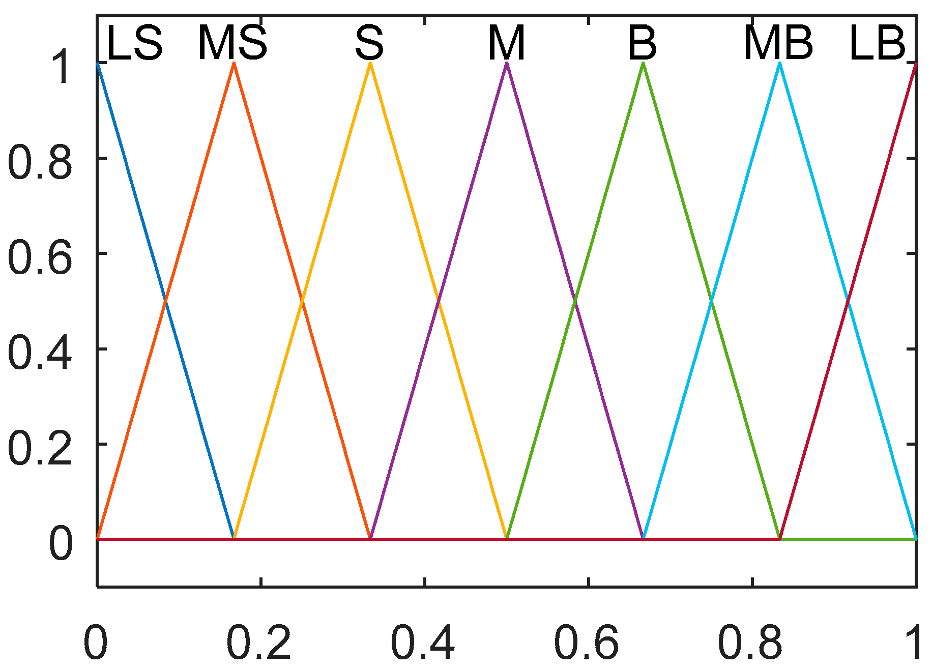
The fuzzy impedance controller was designed based on Mamdani-type fuzzy inference engine and center of gravity defuzzification. The input and output membership functions are defined as
Figure 2 and
Figure 3 respectively. Five membership functions are used for input variables
and
, named as LS, S, M, B, LB in a range of [0, 1], whereas seven membership functions are used for output variables
and
, named as LS, MS, S, M, B, MB, LB in a range of [0, 1]. The following are the scaling functions
where
is the velocity command,
and
are its maximum and minimum values;
is the nominal load force, and
and
are its maximum and minimum values. The nominal load force can be measured in advance. It is the force of the load cylinder when it moves at a desired velocity with a normal load.
and
are the maximum and minimum values of desired mass, and
and
are the maximum and minimum values of desired damping coefficient.
Table 1 and
Table 2 show the fuzzy rules, velocity command
and nominal load force
are the input variables, whereas desired mass
and desired damping coefficient
are the output variables. The goal of fuzzy impedance control is to adjust the load force to an acceptable range and provide an expected dynamic response between velocity and load force. According to the load cylinder in the system, a larger velocity leads to a larger load force that requires a smaller
to improve the dynamics, and a larger
to ease the restriction of the load force, respectively. A larger nominal load force also demands a smaller
and a larger
, because the system is much more vulnerable to disturbances, which means a small change of velocity will result in a larger change of load force.
Considering fuzzy impedance control in the control process, the desired velocity trajectory turns into , and the derivatives become , . , and are the computation results of (9), which are different from , and .
Assumption 2. Based on Assumption 1 and the first-order impedance rule,, , are assumed to be bounded.
5. Stability Analysis of the Whole System
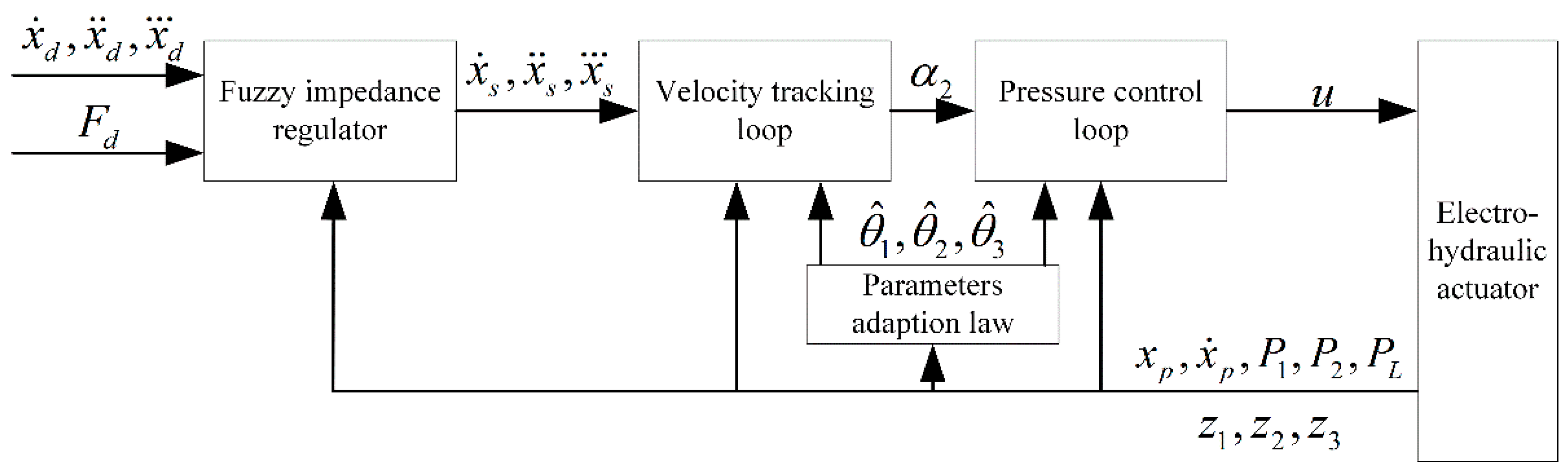
As
Figure 4 shown, a fuzzy impedance controller and a nonlinear velocity controller are synthesized together in the whole cascade system. The parameters of impedance rules are predetermined. Thus, the impedance system (9) is a time invariant first-order system with positive coefficients. According to the concerned load system, the input
is bounded. Therefore, the impedance system is stable based on Routh’s stability criterion.
Defining a sliding function as
it can be seen that the sliding function (38) generates the expected impedance behavior (46), when
vanishes [
46]. The above definitions yield
Since the stability of ARC is already proved, will converge to zero after a finite time only under parameter uncertainties. To make the force vary smoothly, the response of ARC is designed much faster than the fuzzy impedance controller. Thus, and can be finally treated as small enough, since is always set as constant and the load is assumed to vary slowly in practice. Then, can be considered small enough to make converge to zero. Consequently, impedance performance can be guaranteed under certain conditions.
6. Experimental Results
Experiments were conducted to validate the performance of the proposed ARFIC. The drive cylinder and the load cylinder were both controlled by servo valves. Four pressure sensors were utilized. A position sensor was used to obtain the displacement and velocity of the drive cylinder. A data acquisition card was employed to collect data and output control inputs. The control strategy was implemented in the MATLAB Simulink Realtime environment with a 1 kHz control rate.
Firstly, ARC (without impedance control) was tested.
Table 3 lists the parameters of the electro-hydraulic system.
Table 4 and
Table 5 list controller parameters.
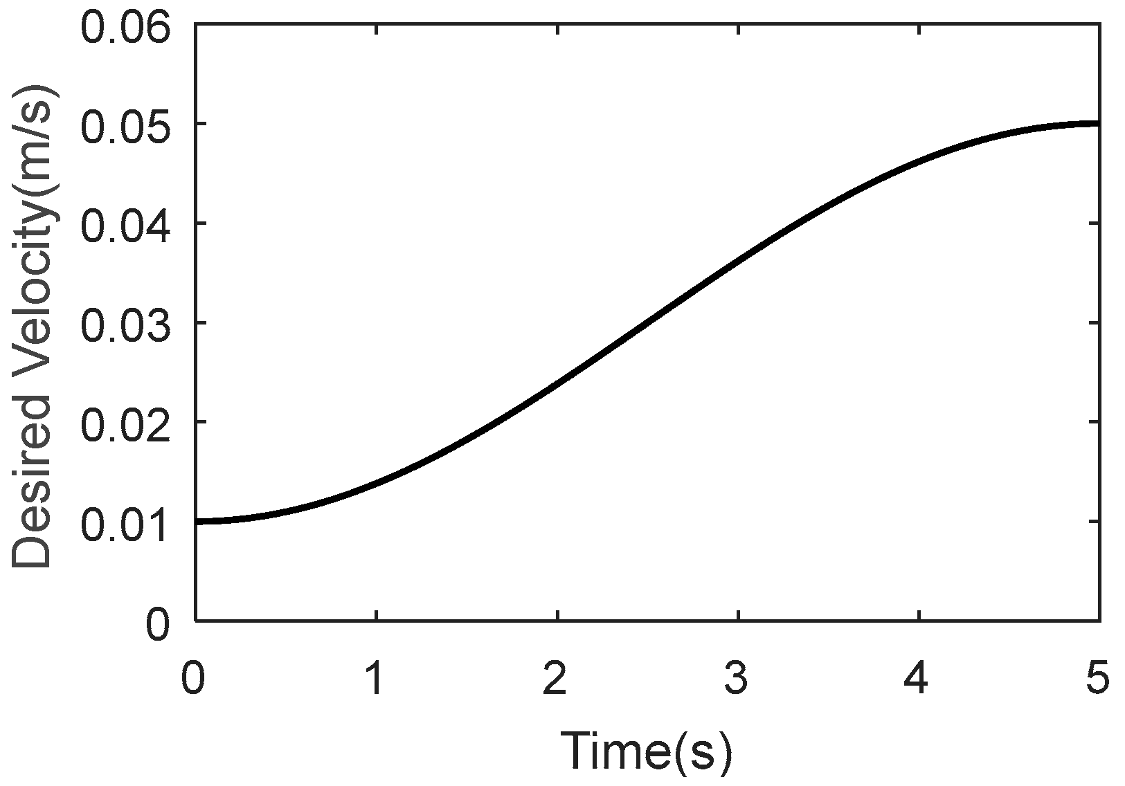
Figure 5 shows the desired velocity trajectory,
.
is the servo valve command of load cylinder. As
Figure 6 shown, the tracking errors of ARC were small.
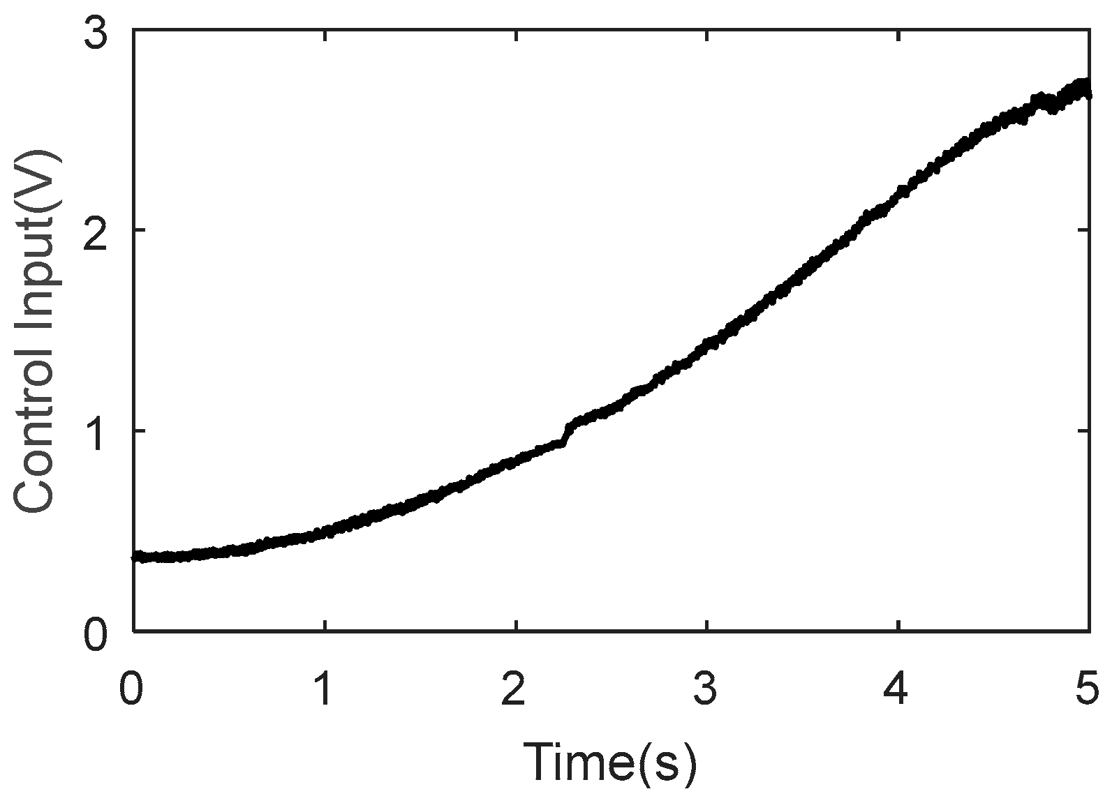
Figure 7 shows the control input and
Figure 8 shows the parameter estimations. ARC achieved accurate velocity tracking, because the parameter uncertainties and uncertain nonlinearities could be compensated. The initial values of parameter estimations were defined according to parameter identification when
. However, it cannot be guaranteed that parameter estimations converged to true values because only control errors were used to drive the parameter adaption law, and persistent excitation condition [
47] may not be satisfied.
Next, ARFIC was verified when the velocity command was constant at 0.02 m/s and 0.04 m/s. The parameters of the fuzzy impedance rule were chosen according to
Table 6. ARFIC was tested compared with ARC (without impedance control), to validate the effectiveness of fuzzy impedance control. A step-like signal was applied to the servo valve which controls the load cylinder. A pressure sensor was used to measure the load force in experiments.
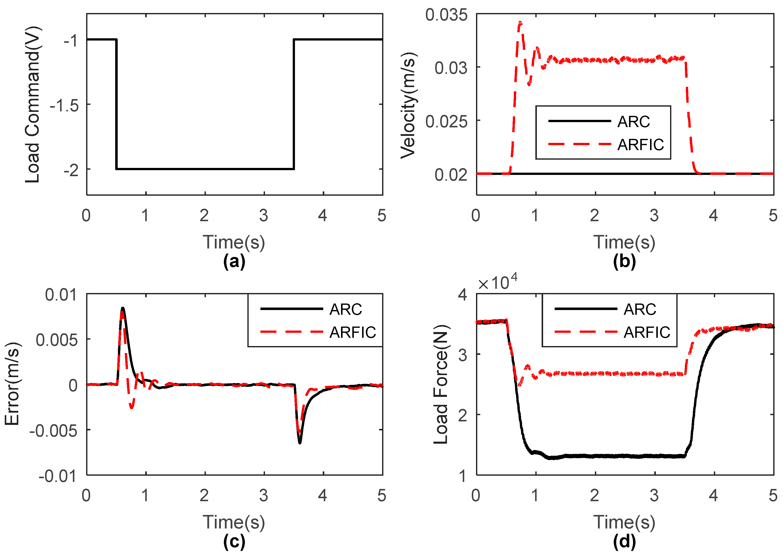
As shown in
Figure 9a, the velocity command was 0.02 m/s, and the load command changed in a step-wise manner from
to
then to
. The regulated velocity commands are shown in
Figure 9b, which guaranteed an expected impedance behavior when load command change occurred. A smooth smaller velocity command was produced by fuzzy impedance control in ARFIC. The load force of ARFIC was kept in a close range, as shown in
Figure 9d. Tracking errors with respect to unregulated or regulated velocity command are shown in
Figure 9c. Both ARFIC and ARC achieved accurate velocity tracking. ARFIC showed a great ability to handle load change through velocity adjustment.
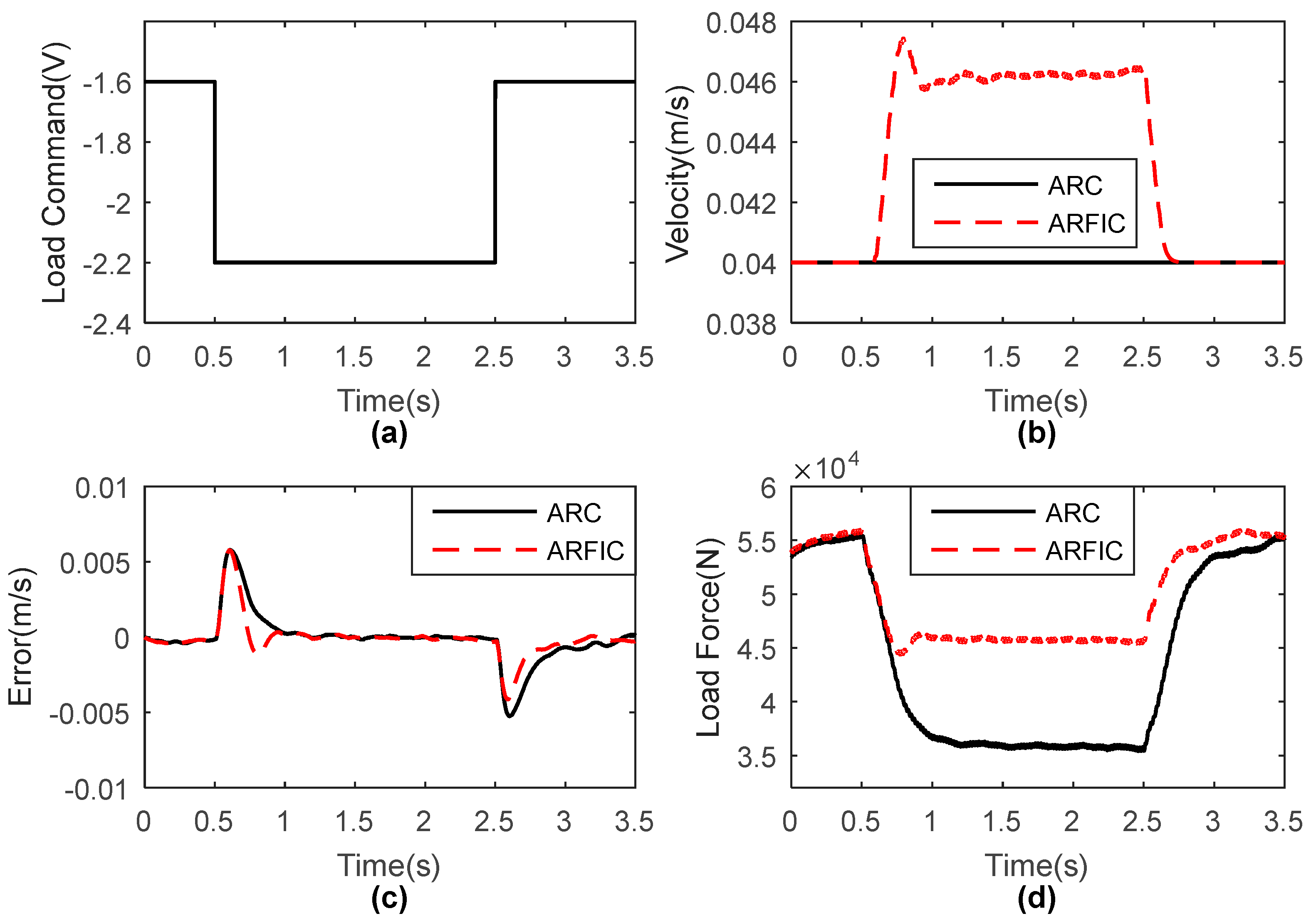
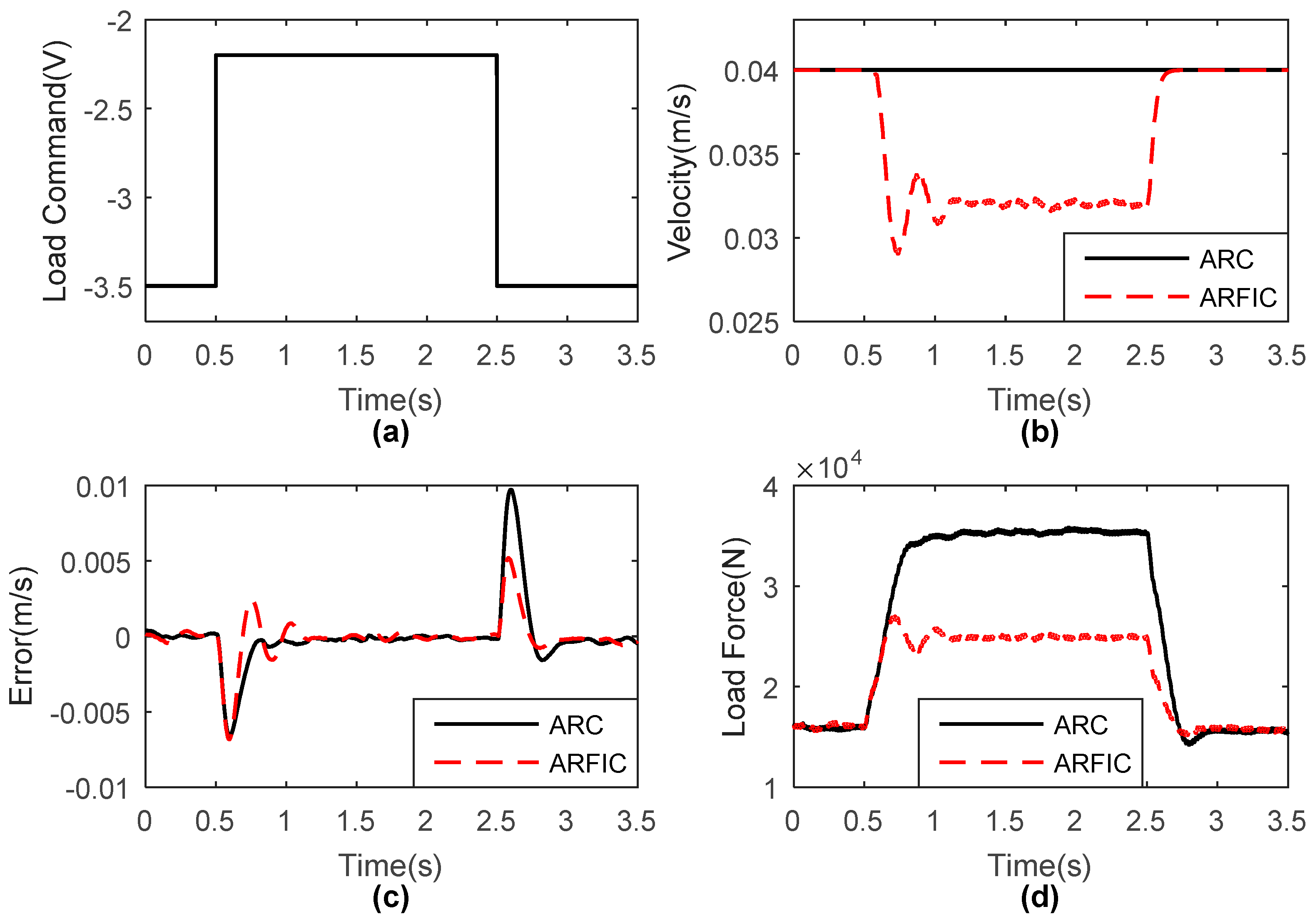
Fuzzy impedance control worked when the deviation of load force exceeded 10% of the nominal value in experiments. It can be seen that dynamic balance behavior was achieved with a fuzzy logic-based impedance control. To validate the effectiveness of ARFIC further, some other load and velocity commands were tested. Similarly, in all kinds of cases, ARFIC demonstrated accurate velocity tracking and impedance regulation between velocity and force. The experiment results are shown in
Figure 10,
Figure 11 and
Figure 12. A smooth regulated velocity command was generated when the load force was beyond the regular range. ARFIC could keep the load force in a close range, comparing with ARC.
Impedance control regulates the load force in a close area which can protect the environment or workpieces. It is quite useful in practice, because motion control has to consider the contact force with the environment or workpieces. ARFIC provides a solution to keep a compromise of velocity control and force control. In ARFIC, contact force is considered as the protection for the system, which should be kept in an acceptable range. Accurate velocity tracking can be achieved, when the contact force is in the regular range, but the velocity command is adjusted, when the contact force exceeds the regular range.


