1. Introduction
As a central topic of computer graphics, rendering is the process of synthesizing an image from a 3D scene. The domain rendering algorithm falls into two branches: rasterization [
1] and ray tracing [
2]. The rasterization method maps geometry in the scene into pixels. This method is very effective in hardware acceleration. Currently, most graphics processing units (GPUs) generate 3D photos in the rasterization method. However, the image quality is limited because it only deals with local illumination. On the other hand, the ray tracing technique generates high-quality 3D photos. It produces 3D images by simulating the optical properties of light, such as reflection, refraction, and shadow. Many modern graphics applications, high-end games [
3], movie special effects [
4], Virtual Reality (VR) [
5], and computer-aided design require a high-quality visual experience that is challenging for rasterization, but is straightforward for ray tracing.
The essence of ray tracing is to find the closest objects that intersect with rays in 3D scenes and then transmit the results of the intersection test to a shader for graph coloring. Researchers proposed the acceleration structure (AS) to accelerate the testing speed. The idea is to arrange the graphics primitives in hierarchical spatial structures. This way, the test of rays and scenes can quickly eliminate those unrelated spaces and identify the closest primitives to the rays. The widely used acceleration structure is a tree structure. The leaf nodes of the tree include all scene primitives, and the internal nodes of the tree are used to subdivide a sizeable spatial representation into multiple smaller spatial regions (KD-trees [
6]) or decompose the objects in the scene into smaller object sets (Bounding Volume Hierarchy (BVH) [
7]). Based on the spatial structures, ray tracing is divided into two main parts: the ray traverse with acceleration structure and the intersection test between ray and primitives. The calculation of this part is one of the main bottlenecks in improving the performance of ray tracing [
8]. This test occupies nearly 70–80% of total calculation time. Therefore, many studies are concerned about the ray traversal and intersection tests that achieve higher performance.
In the past few decades, many researchers worldwide have carried out significant research into ray tracing software and hardware acceleration. Various platforms are used at the hardware acceleration level, including central processing units (CPUs), GPUs, and dedicated hardware. Due to the hardware features, GPUs and dedicated hardware show significant performance advantages. There is a lot of research on optimizing GPUs’ acceleration. Ray tracing was challenging to implement on GPUs because early GPUs did not support general-purpose computation. Nathan A. Carr et al. [
9] made the first attempt to implement ray tracing on a GPU. However, they only implemented the intersection test. This unit reconfigured the geometry engine into a ray engine that efficiently intersects caches of rays for many host-based rendering tasks. Timo Aila et al. [
10] studied the mapping of elementary acceleration structure traversal and primitive intersection onto wide Single Instruction Multiple Data (SIMD)/Single Instruction Multiple Threads (SIMT) machines. Yahshua Lü et al. [
11] proposed the Dynamic Ray Shuffling (DRS) architecture for GPUs to address ray tracing control flow divergences. The critical insight was that the primary control flow divergences caused by inconsistent ray traversal states of a warp could be eliminated by DRS. Experimental results show that, for an estimated 0.11% area cost, DRS significantly improves the SIMD efficiency for the tested benchmarks from 41.06% to 81.04% on average. Lufei Liu et al. [
12] explored integrating the ray prediction strategy into existing GPU pipelines and improving the predictor effectiveness by predicting nodes higher in the tree and regrouping and scheduling traversal operations in a low-cost, reasonable manner. They found that GPU platform optimization pays more attention to the calculation part of the algorithm. Reducing the processing of branches and reducing the redundant operation through the optimization strategy of architecture to maximize the hardware characteristics has achieved good profits in academic research. In addition, commercial GPUs have also introduced accelerated architectures for ray tracing. In 2018, NVIDIA launched the first ray tracing GPU with the first-generation RT Core in Turing architecture [
13]. In 2021, the Ampere architecture with the second-generation RT Core was established [
14]. The RT Cores replace that software emulation, performing the tree traversal and the ray/box and ray/triangle intersection tests. A ray query is sent from the streaming multiprocessor (SM) to the RT Core. The RT Core uses dedicated evaluators to test each ray against the box or, at the leaves of the tree, the triangles that make up the scene. It does this repeatedly, optionally keeping track of the closest intersection found. When the appropriate intersection point is determined, the result is returned to the SM for further processing. In 2021, Imagination added the Ray Acceleration Cluster (RAC) of the PowerVR Photon architecture to the C-series GPU to provide ray tracing IP technology for the mobile phone market [
15]. RAC uses a highly parallel Dual Triangle Tester Unit to improve the efficiency of hardware computing. Its primary function is to perform the intersecting test of the two triangles simultaneously and send the processing results to the next stage. This series’ GPU is divided into single-core and multi-core models applied to mobile and beyond mobile configurations.
In recent years, dedicated hardware has also been widely referenced in ray tracing studies. SaarCOR [
16] is a ray tracing pipeline consisting of a ray generation/shading unit, a four-wide SIMD traversing unit, a list unit, a transformation, and an intersection test unit. The T&I engine [
17] is a hardware acceleration architecture of ray traversal and intersection tests. This architecture adopts an order depth-first layout method to reduce memory bandwidth. It proposes the three-phase ray-triangle intersection and a latency hiding architecture defined as the ray accumulation unit. SGRT [
18] is a real-time mobile ray tracing GPU. It mainly includes two key features: (1) an area-efficient parallel pipelined traversal unit; (2) flexible and high-performance kernels for shading and ray generation. RayCore [
19] mainly includes ray-tracing units (RTUs) based on a unified traversal and intersection pipeline and a tree-building unit (TBU) for dynamic scenes. HART [
20] utilizes heterogeneous hardware resources: dedicated ray-tracing hardware for BVH update and ray traversal and a CPU for BVH reconstruction. It also uses PrimAABB for traversal scheduling. Lee et al. [
21] optimized the SGRT [
18] and proposed two-AABB traversal architecture with two ray-AABB testing units. The experimental results showed that two-AABB was up to 2.9 times faster than the single-pipeline architecture. Kopta et al. proposed STRaTA (Streaming Treelet Ray Tracing Architecture) [
22] to decrease energy consumption on massively parallel graphics processors. Viitanen et al. applied MBVH (Multi Bounding Volume Hierarchy) [
23] to a fixed-function ray tracing accelerator architecture. With primary rays, energy efficiency improves by 15% and performance per area improves by 20%. Another implementation approach is multiple streams, such as a different approach to hardware-accelerated ray tracing, which begins by modifying the order of rendering operations, proposed by Konstantin Shkurko et al. [
24]. The dual steaming approach organizes the memory access of ray tracing into two predictable data streams. E. Vasiou et al. [
25] introduced Mach-RT (Many Chip-Ray Tracing), a new hardware architecture used to accelerate ray tracing. The primary approach combines a ray ordering scheme that minimizes access to the scene data with a sizeable on-chip buffer acting as near-computer storage spread over multiple chips.
From the perspective of existing academic research results and commercial GPUs, ray tracing acceleration has gradually improved computing capabilities with the algorithm’s progress and industrial technology’s development. Due to the different algorithms adopted by different designs and the various purposes of the ray tracing hardware architecture, many strategies have considerable differences in performance and hardware resource overhead. However, they have some performance/area limitations, and we are focusing on a more efficient hardware architecture for ray tracing.
Our main contributions to the literature are as follows:
- (1)
Three optimization methods for ray tracing memory access, branches, and functional units, respectively;
- (2)
A new hardware architecture based on an area-efficient parallel pipelined ray traversal and intersection unit;
- (3)
Implementation of the whole system at the RTL level and assess hardware resource overhead.
The optimization methods are multiple stacks, three-phase break, and approximate method of the reciprocal unit. Multiple stacks store information during ray traversal to ensure system parallelism and reduce memory access. A three-phase break makes the intersection of rays and primitives more efficient and allows an earlier exit from the loop. The approximate method can significantly reduce the hardware overhead and can converge faster. This paper is organized as follows: in
Section 2, we describe the overall architecture design and the data flow. Optimization and design methods for RT engine are discussed in
Section 3. In
Section 4, we mainly evaluate and analyze the proposed architecture and estimate the hardware consumption. The conclusion of the paper is presented in
Section 5.
2. Overall System Architecture
In this section, we describe the overall architecture of the RT engine. We will illustrate our basic design decisions, present the BVH ray tracing algorithm, introduce our system architecture, and then describe the data flow of RT engine.
2.1. Basic Design Decision
There are many decisions to be made in our design, which we will describe next.
Domain-specific architectures: A more hardware-centric approach is to design architectures tailored to a specific problem domain and offer significant performance (and efficiency) gains for that domain. This design approach exploits more efficient parallelism for the specific domain [
26]. This design can speed up some applications compared to running the entire application on a general-purpose CPU. DSAs can perform better because they are better suited to the application’s needs. In addition, DSAs can make more effective use of the memory hierarchy. Memory access has become much more costly than arithmetic computations, as Horowitz [
27] noted.
Acceleration structure: Many types of acceleration structure research focus on kd-tree and BVH. In the last two decades, the bounding volume hierarchy (BVH) has become the de facto standard acceleration structure for ray-tracing-based rendering algorithms [
7]. The BVH traversal algorithm usually occupies less memory bandwidth and has the characteristics of a compact traversal state. NVIDIA [
14] and Imagination [
15] GPUs also choose BVH as an acceleration structure in the industry. We choose binary-based BVH in our design. It can effectively reduce hardware overhead and design costs compared to other kinds.
Per-ray traversal: There are two ways to determine ray-tracing traces. Packet traversal means a group of rays following the same tree path. This is achieved by sharing the traversal stack among the ray, which means that some rays will traverse those nodes which will not intersect. The other is per-ray traversal, which allows each ray to traverse independently, traversing the node’s children only when the node intersects with the ray. Each ray requires a separate traversal stack to store the ray’s data. Our design chooses the second way [
7].
Primitive type: We use only triangles as the primitive type. This choice can improve system performance and simplify designs because this method can eliminate branches of different graphs. Therefore, other graphics before rendering should be converted into triangles, just like rasterization-based GPU processing methods.
First-hit traversal: This approach is the most widely used and is indispensable for computing the radiance at a shading point, which finds the nearest object in the direction of a ray from its origin. In binary-based BVHs, this approach can efficiently push the farther intersected node onto a stack and visit the closer one first [
7].
2.2. Ray Tracing Algorithm
The BVH ray traversing algorithm can be described as the while–while loop [
10] in Algorithm 1. This algorithm’s initial value sets the node’s address to the root node of BVH, and the initial value of the bottom of the stack is a mask. When a ray enters this loop, it traverses from the root node. The outer while loop determines whether the current ray has finished. When the node’s address is the mask of stacks, this indicates the current ray has completed the traversal. The first inner while loop is a depth-first traversal of BVH. The ray must intersect against the child nodes when the node is an internal node. If two child nodes intersect against the ray, push the farther children into the stack, and the other transfer to the next unit; if only one child node is intersected, traversal this child node; if no child node is intersected, then pop the stack. The second inner while loop is the intersection of leaf nodes. The primary purpose of this loop is to determine the intersection of rays and primitives of the scene and calculate the intersection. The calculation results of this loop can be used by the shader to render an image. After completing this part, the current leaf node is complete. Then, it pops the stack. We adopt a multiple-stacks approach to solve the parallelism of ray tracing. In addition, we also design two improved methods to accelerate the speed of the triangle intersection test. We will introduce each of these methods in detail next.
Algorithm 1 is a standard ray tracing algorithm for BVH. The current ray tracing algorithm introduced stackless-based BVH Traversal, such as Hapala et al. [
28]. This method uses simple logic to sort each node’s parent pointer and minimize the stack’s use. However, it requires re-visiting internal nodes, which will cause some redundant operations. Binder et al. [
29] present a BVH backtracking algorithm in constant time with two tables. The primary method is to prepare the bit trail and the current key for each level, which causes BVH’s storage space to increase. In addition, two tables are needed to occupy ample storage. The full-stack method will be easier and more efficient in dedicated hardware than those implementation methods. In addition, many later works have also studied how to use multi-branching wide BVH [
23,
30]. Compared with wide BVH, using binary-based BVH can reduce the expenses of the operation and reduce redundant processes. So, we finally chose this standard algorithm.
| Algorithm 1: BVH Ray Tracing Algorithm |
| Input: ray, rootNode of the BVH |
| Output: intersection results |
hit ← false curNode ← rootNode Stack ← ϕ whilecurNode ≠ ϕ do
|
![Applsci 12 09599 i001]() |
2.3. System Architecture
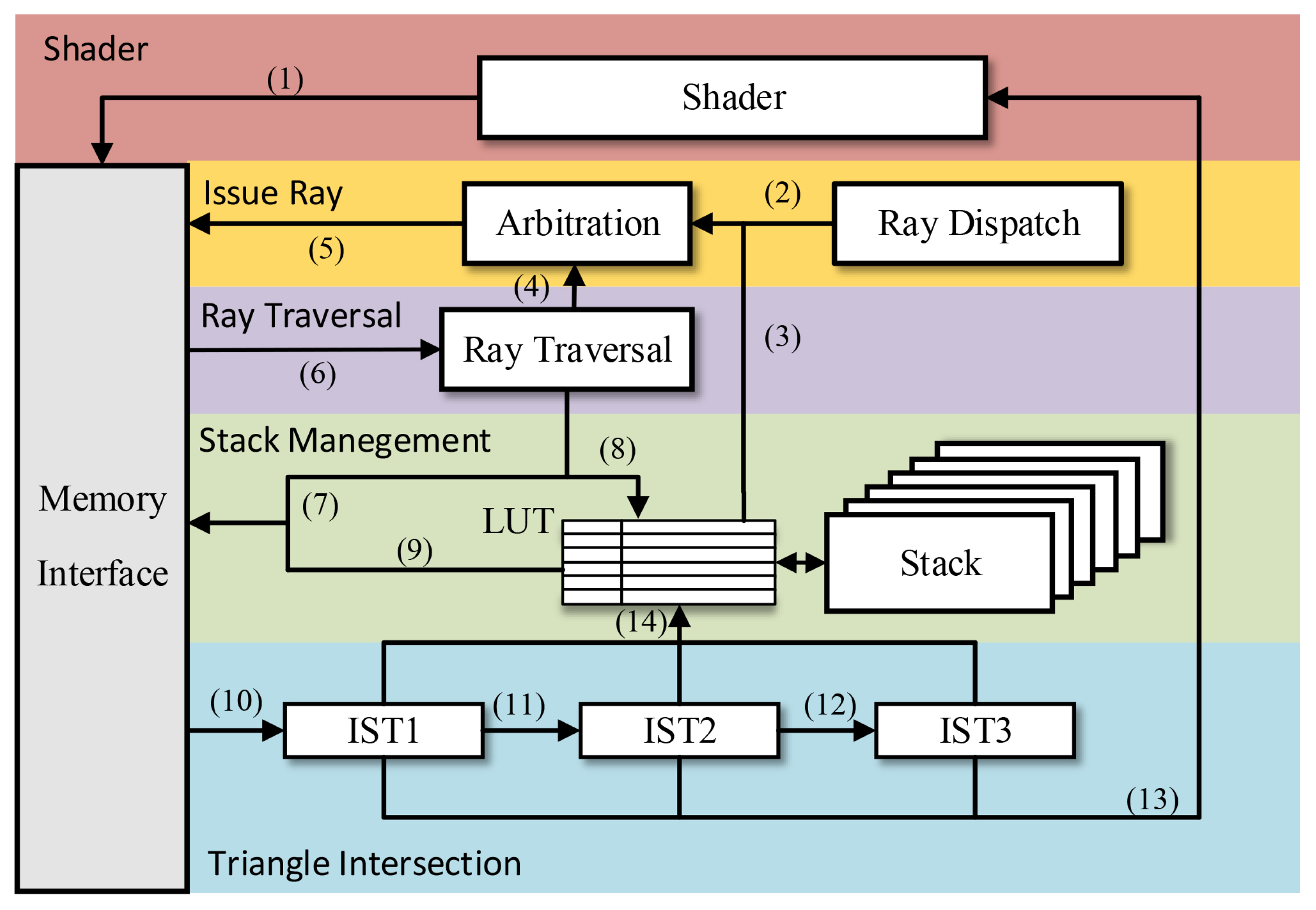
Figure 1 shows the overall design of the RT engine, which mainly includes memory and five parts. These five parts are the Shader, Issue Ray, Ray Traversal, Stack Management, and Triangle Intersection.
The Shader’s (SHD) purpose is to provide our system with rays, BVHs, and primitives data. In addition, we can render our system results and generate expected rendering images. This part is in conjunction with the CPU or GPU existing shader.
The Issue Ray primarily determines the system’s rays and nodes’ data input according to different access requests. This part includes two units. One is Arbitration (ARB), and the other is Ray Dispatch (DIS). The Ray Dispatch is mainly used to handle the dispatch request of rays. When the ray in the system is completed, the new ray will issue. The design of ARB deals with data conflict. This conflict comes from nodes returned from the Ray Traversal unit, nodes from stacks, and issue requests. So, to avoid data conflict, we set up arbitration for the preliminary processing of data requests. To handle the ray of the earlier issues faster, the arbitration method of the three requests is the top priority of the node from stacks, the secondary of the traversal of the unit, and finally, the newly issued rays.
The Ray Traversal (TRV) unit is essential to the entire system design. This part corresponds to the in Algorithm 1. The module completes the intersection between rays and BVHs. Input is ray data and BVH data, and output results control what will happen next. If the ray intersects the two child nodes of BVH, select the farther node, push it to the stack, and choose the one nearer to the following stage. If the ray intersects only a child node of BVH, it needs to be judged whether the node is a leaf node. If the ray does not intersect with the two child nodes of the BVH, then pop the stack.
The Stack Management unit is the key to ensuring multiple rays in the system parallel processing. This part corresponds to the and in Algorithm 1. Its primary role is to operate the stack according to the results of the Ray Traversal unit and the Triangle Intersection unit. To ensure the stacks’ accuracy and order, we added a LUT (Look Up Table). This unit ensures that the data of rays and stacks can correspond.
The Triangle Intersection (IST) unit tests the intersection of the triangle and the ray of the leaf node, which corresponds to the
in Algorithm 1. For the design of this part, we refer to the Woop algorithm [
31]. This algorithm has three logical parts: the ray-plane test, the barycentric test, and the final hit-point calculation. IST1 completes the calculation of the ray-plane test. IST2 completes the barycentric test. IST3 completes the final hit-point calculation. The design of this unit uses two optimization methods to achieve a system performance improvement, which we will describe in detail in the subsequent chapters.
Table 1 illustrates how rays move from unit to unit. The numbers in
Table 1 correspond to the numbers in
Figure 1.
3. Proposed RT Engine Architecture
3.1. Multiple Stacks
As shown in Algorithm 1, each ray is input to the TRV unit, and TRV will send the information of nodes to the stack based on the results. If the ray intersects with two child nodes, the farther node will be pushed to the stack, and closer nodes will be sent to the next stage. If the ray does not interact with two child nodes, it will send a pop stack request. On the other hand, when the triangle intersection test is completed, the IST will request the pop stack. The stack features save the nodes and ensure the accuracy of the integrated process.
However, only one ray can be processed when there is only one stack in the system. This design cannot achieve multiple ray parallel processing, resulting in a waste of hardware resources. In this case, we consider setting a group of stacks to save the nodes’ information of multiple rays. This kind of design allows multiple rays to process at the same time.
Stack Management is set in our system design to handle stack operations. To solve the system’s accuracy when multiple stacks store nodes’ information, we set up the LUT unit to manage stacks. The data stored in the stack are the nodes’ address, and the nodes may be internal nodes or leaf nodes. As shown in
Figure 2, the push request is from the TRV, and the pop request is from TRV and IST. After the MUX selects the request, the current corresponding ray’s address is compared to the ray’s address in the LUT. After matching the ray’s address, the request will be sent into the corresponding stack. Such a design guarantees the parallelism of the system while ensuring accuracy. Less hardware resource overhead is used, achieving a relatively high performance improvement.
Compared with a single stack, the performance of multiple stacks by LUT can improve by 9.99–20.78×.
3.2. Three-Phase Break for Intersection
Figure 3 shows the method from Woop [
31], which is a fundamental algorithm for triangle intersection tests. First, a ray-plane test depends on whether the ray and triangle intersect within the t intervals. After this test, the next phase is used to perform a barycentric test. This test phase checks the barycentric coordinates (u, v) to determine the point in the hit within the triangle or outside. If the ray passes these two tests, the value of t, u, and v can be calculated. The last phase comes from the intermediate value calculated by the first two phases, determining Cramer’s rule.
We set up IST1 to complete the ray-plane test. If it misses, it will break to LUT. This unit calculated t value is first checked. The results mainly depend on whether the ray and the triangle intersect at the t. The pop stack request is sent to the LUT if the test does not pass. If the test passes, the t value will transmit to the IST2 unit to perform the following process. The IST2 unit is for barycentric and obtains u. Then, we check u. A pop stack request is issued to the LUT if the test is not passed. If the test passes, the obtained u value will transmit to the IST3 for processing. The IST3 phase processes the v value, which can determine if the ray intersects with a triangle and can return the value of t, u, and v. If we can test it as early as possible, we can get stack operations to the LUT as soon as possible. This design allows the triangle intersection test to get the output results earlier.
The simulation results show this method can effectively improve performance. For the simulation results, see
Table 2.
means it did not pass the ray-plane test, exit
, etc. For the test scene, see
Figure 4.
3.3. Approximation Method for Reciprocal
In Algorithm 1, the
needs reciprocal operation once. Our design uses the approximation method for the reciprocal, which combines Parabolic Synthesis [
32] and Second-Degree interpolation [
33]. Compared to other methods, this approach converges faster and has a smaller chip area. Our floating-point calculation unit uses IEEE 754 standards. In the first step, we extracted the sign bit, the exponent bits, and the significand bits of the divisor. The significand bits are issued to the inverter where the Harmonized Parabolic Synthesis (approximation) is performed. In this block, the coefficients of the synthesis method are stored in look-up tables.
To enable the entire process to handle the parallel processing, the processing of the exponent is performed as follows:
removing the bias:
inverting the sign and adding the bias:
when equations 1 and 2 are combined:
The schematic diagram of the entire process is in
Figure 5. The reciprocal unit has been tested for every possible input. The max error is 1.18358967 ×
(≈
) which is smaller than the machine epsilon (
) (upper bound for the error) that is commonly defined as
(by ISO C, Matlab, etc.) for the single-precision floating-point format.
Reduced precision has many studies in ray tracing, such as Vaidyanathan et al. [
34], aiming to reduce the accuracy of BVH to improve performance. This method requires only a few hardware resources to reduce traversal calculation complexity while maintaining robust image quality. Our approach is different from the BVH accuracy. It is mainly intended to maintain the accuracy of BVHs and find a novel way to reduce accuracy and hardware resources in reciprocal operation.
To compare the reciprocal computing unit used by RT engine, we compare the area overhead with the same functional units in other academic research. For comparison data, see
Table 3. The table lists several academic research studies about ray tracing on the reciprocal area. The process of SGRT and HART is 65 nm, and the clock rate is 500 MHz. We perform an approximate transformation to NAND2 under the same clock rate for a better comparison.
4. Simulation Results and Analysis
To achieve more accurate functional verification, we implement our system at the RTL level with Verilog HDL (Hardware Description Language) by Chisel language [
35]. We create a simulator to cycle accurate simulations by Verilator and Scala, which can verify the accuracy of the design. After simulation, the results provide the total number of cycles used to generate a scene, hardware utilization, average steps, and hit results.
Our system uses BVHs with SAH [
36].
Figure 4 shows the four test scenes: Conference (350K Tris), Fairyforest (186K Tris), Sibenik (97K Tris), and Sanmiguel (12.1M Tris), respectively. We choose the primary ray to simulate the results. All scenes are rendered into 1920 × 1080 resolution. Finally, we use the synthesis tool to assess the hardware overhead.
The hardware setup is structured as follows. The RT engine has a total of 25 groups of stacks. The depth of each stack is 64. Set three sets of FIFO with a depth of 25 in the ARB. In addition, this paper focuses on the calculation of traversal and intersection tests, so no cache is set.
4.1. Hardware Complexity and Area Estimation
In
Table 4, we compare our architecture with other dedicated architectures. Our architecture significantly reduces the number of floating-point units and has several features. First, our algorithm is simpler and more efficient than other architectures. Second, we use multiply–accumulate units to occupy less area than other architectures. Third, we use fewer reciprocal units, as other architectural reciprocal units or divider units occupy a large amount of chip area. Therefore, we can conclude that our architecture is more efficient than previous researchers’ methods.
Table 5 summarizes the area estimation of RT engine. Stacks, FIFOs, and functional units require hardware resources. We estimated the area of this design to be 55.9% of the total area for arithmetic units. Finally, we concluded that the RT engine occupies a 0.48 mm
area with 28 nm process under an 850 MHz clock rate.
4.2. Simulation Results
Table 6 shows our simulation results at the 850 MHz clock rate. It can be found from the simulation results that different test scenes are different in resource utilization and stack utilization rates. In general, the more complicated the test scenes, the higher the utilization rate of the stack. IST will maintain a relatively low utilization rate, and the performance will decrease. Under the configuration of a single core, our RT engine performance is from 16.59–92.74 MRPS (million rays per second).
Table 7 shows that our architecture performed better than existing ray tracing architectures. To achieve performance comparison and assessment fairly, most of the performance uses the same scene with our architecture. If there are none that are the same, we list the best performance. The area data in
Table 7 is the computing units of traversal and intersection without cache, except that RayCore and Two-AABB did not mention the cache area.
In
Table 7, the performance/area of our architecture is 193.21 MRPS /mm
, which is 2.4 × higher than the best results of other academic research. It can be found that the process (nm) significantly impacts the evaluation results. Our efficiency is also higher than RayCore [
19] and Two-AABB [
21] under the same process. One of the main reasons is that many architectures use SIMD or Multiple Instructions Stream Multiple Data Stream (MIMD) architectures, which are inefficient due to branching and memory access issues. Our single pipeline architecture is more efficient for ray tracing. Another key reason for the difference in performance/area is that the design goals of these architectures are different. For example, STRaTA [
22], Dual Streaming [
24], and Mach-RT [
25] focus on the latency and conflict of memory access, so the method of multiple Thread Multiprocessors (TMs) is used. This design can effectively improve the overall performance, but there would be a lot of redundant hardware resources. RayCore [
19] mainly focuses on dynamic scenes, so it is not dominant in this comparison. The focus of these designs is different from ours. RT engine’s low hardware consumption comes from our careful design, algorithm improvement, and fabrication technology innovations.
MRPS/mm
is a fair unit of measurement for ray tracing hardware because it is relatively independent of the resolution of the scene rendering [
37]. As can be seen from the data in
Table 7, our architecture is better than other researchers’ results in terms of efficiency. This result is encouraging because these designs could potentially be used as a co-processor for accelerating ray tracing performance on existing or future GPUs or CPUs.

 ,
, 


