Article

Compact 15 mJ Fiber–Solid Hybrid Hundred-Picosecond Laser Source for Laser Ablation on Copper

1
School of Physics, Changchun University of Science and Technology, Changchun 130022, China
2
Key Laboratory of Jilin Province for Spectral Detection Science and Technology, Changchun University of Science and Technology, Changchun 130022, China
*
Author to whom correspondence should be addressed.
Appl. Sci. 2022, 12(19), 9621; https://doi.org/10.3390/app12199621
Submission received: 3 August 2022 / Revised: 1 September 2022 / Accepted: 22 September 2022 / Published: 25 September 2022
(This article belongs to the Section Applied Physics General)

Abstract

:
We report on a millijoule-level fiber–solid hybrid hundred-picosecond laser system with a stable performance and compact structure. The laser system is based on a master oscillator power amplifier structure containing an all-fiber master oscillator, a quasi-continuous-wave side-pumped Nd:YAG regenerative amplifier, and a double-pass amplifier. By using the filtering effect of fiber Bragg grating and the dispersion characteristics of single-mode fiber stretcher, the spectrum broadening caused by self-phase modulation effect is effectively suppressed. Thus, the gain linewidth of the Yb-doped fiber seed source and Nd:YAG laser amplifiers is accurately matched. The reason for thermally induced depolarization in the solid-state laser amplifier is theoretically analyzed, and a more flexible depolarization compensation structure is adopted in amplifier experiment. Furthermore, the pulse energy of 14.58 mJ and pulse width of 228 ps is achieved at 500 Hz repetition rate. The central wavelength is 1064.1 nm with a 3 dB bandwidth of 0.47 nm. The beam quality factors in the horizontal and vertical directions are 1.49 and 1.51, respectively. This laser system has a simple and compact structure and has a power stability of 1.9%. The high pulse energy and beam quality of this hundred-picosecond laser are confirmed by latter theoretical simulation of copper laser ablation. It is a very practical laser system for material processing and laser-induced damage.

1. Introduction

Picosecond pulsed laser sources have been widely used for a variety of industrial manufacture and basic scientific applications, such as material processing [1,2], laser-induced damage [3], medical diagnosis [4], nonlinear optics [5,6], and laser ranging [7,8], all of which benefit from the narrow pulse width, large single-pulse energy, and sufficiently high peak power. In particular, the millijoule-level pulsed laser source with hundreds of picoseconds has great application potential in the field of material processing and laser-induced damage. Nanosecond laser sources can achieve high processing efficiency by virtue of their high-energy characteristic. However, the ablation mechanism of the nanosecond laser sources is mainly the photothermal effect, which will generate a large amount of heat. As a result, cracked areas and molten areas tend to be generated near the processing area, resulting in worse processing quality. For ultrashort pulsed laser sources (<10 ps), the ablation mechanism is mainly photoionization. Ultrashort pulsed laser sources have narrow pulse width and high peak power density, which can cause a sharp rise in the temperature of the processed material in a short period of time. Therefore, there is no slow accumulation of lattice heat, enabling high-precision processing quality. However, when a narrow pulse is amplified, it is extremely easy to cause damage to optical components because of its high peak power. It can be seen that it is still difficult to obtain high energy and high peak power simultaneously for ultrashort pulsed laser sources. For this reason, the lower energy limits their processing efficiency. In contrast, the hundred-picosecond pulsed laser source has a pulse width in the nanosecond to femtosecond range. It not only has the characteristics of narrow pulse width, small thermal effect range, and high accuracy, but can also ensure high-energy and high peak power output, thereby reducing the damage threshold of the material and accelerating the damage process. Therefore, the hundred-picosecond pulsed laser system is the most promising application light source to realize the above characteristics. In the traditional industrial field, product quality and production efficiency can be improved by using a millijoule-level hundred-picosecond laser source [9]. Therefore, it has certain theoretical significance and practical value to provide a reliable and stable millijoule-level hundred-picosecond pulsed laser source for research on material processing and laser-induced damage, which can enhance the damage efficiency of materials.
The high-energy picosecond laser pulses are usually obtained by a master oscillator power amplifier structure with high gain medium [10,11,12,13]. In general, this structure is based on a fiber or solid-state mode-locked laser oscillator as the front-end seed source, followed by further energy enhancement through regenerative amplification or multi-pass amplification technology. It can be seen that a stable front-end seed source is the foundation of a laser amplifier. In the current reports, most of them used solid-state Nd:YVO4 mode-locked laser oscillators based on a semiconductor saturable absorber mirror (SESAM), which had a repetition rate of 80 MHz [14,15]. However, the realization of stable mode-locking by the solid-state mode-locked laser oscillator is limited by the length of the resonator, which is harmful to the miniaturization of the system front-end. In addition, a large number of spatial separation elements are very sensitive to the environment, which leads to the instability of the mode-locked pulses. Furthermore, the etalon was used to broaden the pulse width and thus achieve efficient energy amplification. However, the broadening was limited to tens of picoseconds. Compared with a traditional all-solid-state seed source, a fiber seed source has unique advantages, including good beam quality, high conversion efficiency, compact structure, good thermal management, and strong anti-interference ability. Furthermore, multistage fiber amplifiers can achieve high average power up to hundreds of watts [16,17]. However, due to high peak power during the picosecond pulses amplification process, unwanted nonlinear effects and optical damage will be generated. Therefore, it is rather difficult for fiber amplifiers to realize high energy.
To obtain a stable picosecond laser source with high pulse energy, the method of combining a fiber seed source with a multistage solid-state laser amplifier can be adopted, and this is a very effective method. For laser amplifiers, according to different shapes of gain media, they can be divided into thin-disc amplifiers, slab amplifiers, and rod or bulk amplifiers. The thin-disc amplifier has obvious advantages under high-energy pumping due to its excellent thermal management mechanism, which can guarantee both high beam quality and high-energy laser output [18,19]. However, the lower single-pass gain and complex multi-pass structure significantly increase the technical complexity and operation maintenance cost of the amplification system. By contrast, the slab amplifier is quite advantageous in terms of technical complexity [20,21]. Nevertheless, the slab amplifier has a special pumping structure, which requires a large number of coupling and shaping systems. Moreover, it requires high-precision assembly to control the beam quality of the output; thus, the cost is relatively high. Additionally, it is difficult to grow large-sized slab crystal; hence, it is much less powerful than rod or bulk laser amplifiers in terms of output energy. The rod or bulk laser amplifier still has good development prospects because of its advantages of simple structure, mature pump module technology, and absence of complex shaping system [22,23,24]. The Nd:YAG crystal is the most common gain medium in picosecond rod or bulk amplifiers. The upper level lifetime of Nd:YAG gain medium is 230 μs, which has high gain and extraction efficiency. Currently, Nd:YAG regenerative amplifiers and Nd:YAG multi-pass amplifiers are promising solutions to further amplify the energy of the seed source for subsequent applications. In 2007, John et al. demonstrated a 130 mJ fiber–solid hybrid amplifier with a repetition rate of 300 Hz, and its output pulse width was adjustable from 350 ps to 600 ps [25]. In 2014, Wang et al. built a 112 mJ fiber–solid hybrid amplifier, which provided pulse durations from 500 ps to 2 ns at a repetition rate of 100 Hz [26]. In 2021, Lv et al. demonstrated a sub-nanosecond fiber–solid hybrid Nd:YAG laser system, which generated a single-pulse energy of 120 mJ and a pulse width of 500 ps at a repetition rate of 100 Hz [27]. In these reports, the single longitudinal mode continuous-wave (CW) fiber lasers were employed as the master oscillators. The modulation of pulse duration and temporal shape of the master oscillators required both acousto-optic modulation (AOM) and electro-optic modulation (EOM) technology. Therefore, this scheme needs additional modulators, resulting in expensive cost and complicated configuration. Another method is to adopt the fiber master oscillator based on SESAM mode-locked technology. In 2016, Michailovas et al. developed a 62 mJ, 1 kHz fiber–solid hybrid amplifier system, which was seeded by a SESAM mode-locked fiber seed source with a repetition rate of 60.3 MHz and a pulse width of 520 ps [28]. However, the SESAM was placed on a mirror mount. It is necessary to insert free-space coupling elements to realize the oscillation of the signal light in the cavity. Moreover, in order to achieve a stable mode-locked pulse output, it is necessary to increase the length of the resonant cavity to obtain more longitudinal modes in the cavity. These are not conducive to the miniaturization, integration, and all-fiberized structure. Moreover, the difficulty of system adjustment and alignment is increased, which is unfavorable for achieving stable mode-locked pulses output. In 2014, Lian et al. reported a CW laser diode end-pumped Nd:YAG regenerative amplifier, which was seeded by a SESAM mode-locked all-fiber seed source. The mode-locked pulse trains with a repetition rate of 38 MHz were injected into the 1 kHz regenerative amplifier, and a single pulse energy of 1.5 mJ was obtained [29]. The linear cavity SESAM passively mode-locked picosecond all-fiber oscillator can realize stable mode-locked pulses at a lower repetition rate; thus, that it has a sufficient resonant cavity length, while ensuring a simple and compact system structure. In addition, it is insensitive to external temperature and air disturbances, which further improves the stability of the system. It can be seen that the combination of an all-fiber seed source based on SESAM mode locking and a multistage Nd:YAG solid-state laser amplifier is an effective method to establish a highly stable 10 mJ-level picosecond laser source. Furthermore, the pulse width of hundreds of picoseconds can be obtained by fiber stretcher, thereby further reducing the volume of the whole system.
In this paper, we first designed a compact hundred-picosecond fiber–solid hybrid laser source operating at 500 Hz repetition rate. It consists of a home-made SESAM mode-locked picosecond fiber seed source, a quasi-continuous-wave laser diode side-pumped Nd:YAG regenerative amplifier, and a double-pass amplifier. Meanwhile, we study the gain linewidth matching of Yb-doped fiber seed source and Nd:YAG laser amplifiers, and the thermal effects compensation in solid-state laser amplifier. Consequently, a laser pulse with a single pulse energy of 14.58 mJ and a pulse duration of 228 ps at central wavelength of 1064.1 nm is obtained, corresponding to a 3 dB spectrum bandwidth of 0.47 nm. The beam quality factors along the x-axis and the y-axis are 1.49 and 1.51, respectively. Thanks to high pulse energy and beam quality of this laser source, we realize the high-quality damage effect on copper material in the latter theoretical simulation. This laser source with extremely high compact and stability, which delivers laser pulse with a millijoule-level and hundred-picosecond profile, supplies a promising light source for fine processing and laser-induced damage.

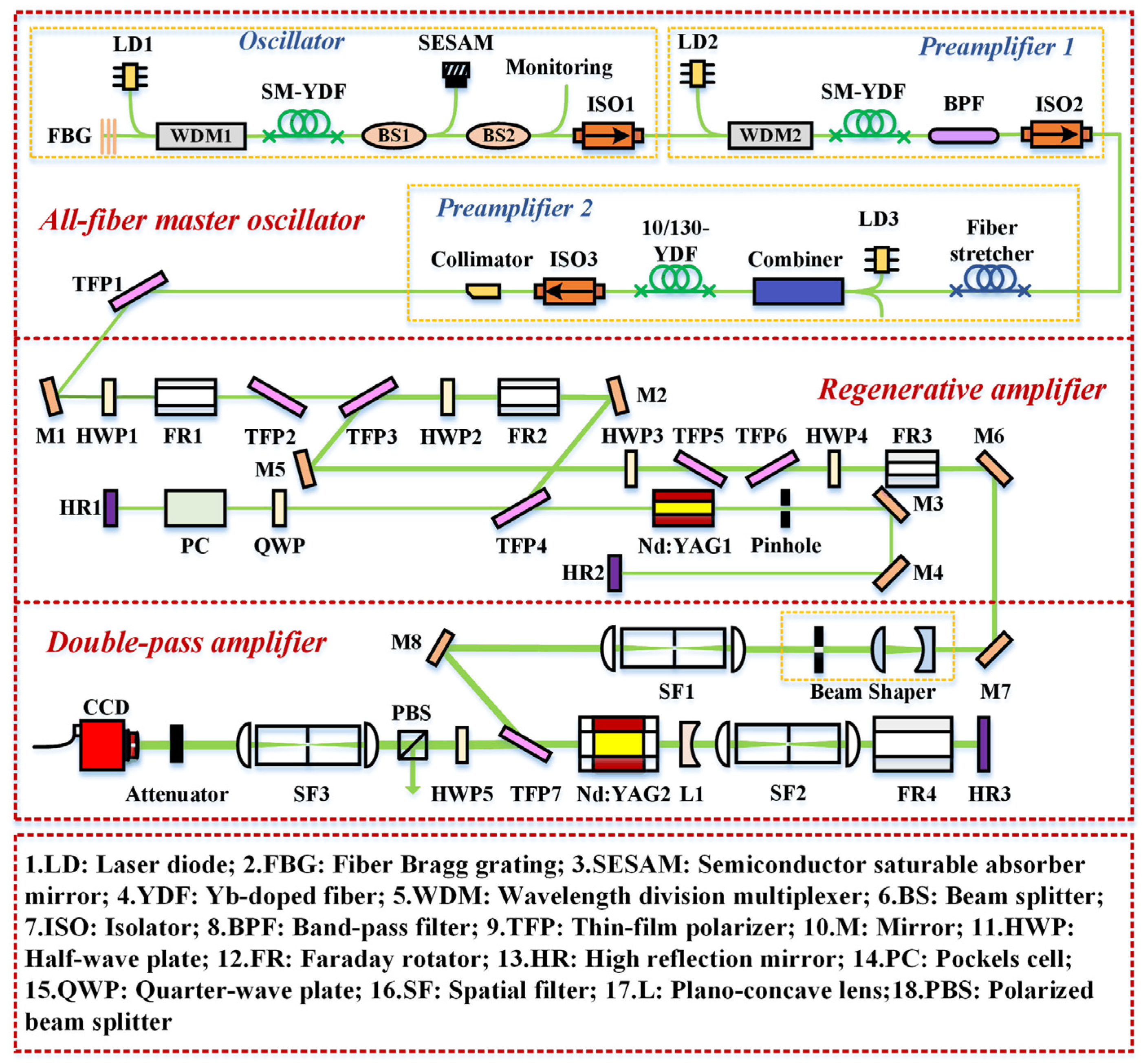
2. Experimental Setup

Figure 1 shows a schematic diagram of fiber–solid hybrid master oscillator power amplifier, which consists of an all-fiber master oscillator, a quasi-continuous-wave (QCW) laser diode side-pumped Nd:YAG regenerative amplifier, and a Nd:YAG double-pass amplifier.

2.1. All-Fiber Master Oscillator

The self-made all-fiber master oscillator is composed of a mode-locked laser oscillator and a two-stage fiber preamplifier. The oscillator is an all-fiber SESAM passively mode-locked laser, which provides seed pulses with average power of 11 mW and repetition rate of 28.49 MHz. It is operated at a central wavelength of 1064.1 nm with a 3 dB spectral bandwidth of ~0.12 nm. Then, the average power is amplified to 50 mW by a single-mode Yb-doped fiber preamplifier (preamplifier 1); the pulse width is measured to be 40 ps, and corresponding peak power is 44 W. A 1350 m long single-mode passive fiber is selected as a pulse stretcher to broaden the pulse width to hundreds of picoseconds. The fiber stretcher is proposed to accurately match the gain spectrum of Yb-doped and Nd-doped lasers. The last stage of the all-fiber master oscillator is a 10/130 μm double-clad pumped fiber preamplifier (preamplifier 2), which further increases the average power of stretched pulses to provide sufficient power for the follow-up Nd:YAG solid state amplifiers. When the pump power of the LD3 is 1.5 W, the output power is further amplified to 580 mW. The collimator is adopted to align and expand the seed laser beam output from all-fiber master oscillator to achieve cavity mode matching with the regenerative amplifier. In particular, to improve the stability of the front-end fiber seed source, we designed engineering prototypes for the fiber oscillator and the fiber amplifier, respectively. We realized the productized design of the front-end fiber seed source through fixing, packaging, and anti-vibration optimization of all fiber components. Among them, the prototype size of the fiber oscillator was 180 × 140 × 28 mm3, and the prototype size of the fiber amplifier was 380 × 170 × 80 mm3.

2.2. Nd:YAG Regenerative Amplifier

Before being injected into the regenerative amplifier, the seed pulses from the all-fiber master oscillator pass through two sets of spatial optical isolation systems. The spatial optical isolation system is usually composed of a thin-film polarizer (TFP), a half-wave plate (HWP), and a Faraday rotator (FR). In our system, two sets of spatial optical isolation systems are employed to ensure additional protection of the all-fiber master oscillator. Among them, the first group of spatial optical isolation systems consists of TFP1, HWP1, and FR1. The second group of spatial optical isolation systems consists of TFP2, TFP3, HWP2, and FR2. The laser diode (LD) side-pumped Nd:YAG regenerative amplifier has a linear flat–flat (HR1, HR2) cavity, with a stable cavity mode. M3 and M4 are 45° reflective mirrors, which are used to fold the cavity length and reduce the geometric size of regenerative cavity. The dimension of the Nd:YAG gain medium is 3 mm × 65 mm, which has a Nd3+ doping concentration of 0.5%. The gain medium is side-pumped by an 82.5 W QCW laser diode at a pump wavelength of 808 nm, and the pump duration is 250 μs. The thin-film plate (TFP4), quarter-wave plate (QWP), and Pockels cell (PC) constitute the pulse selector in the regenerative amplifier. The repetition frequency of the regenerative amplifier is controlled to 500 Hz by a PC electro-optical switch with a quarter-wave voltage. An electro-optical Q-switch driver provides all time delay signals for the master oscillator and latter pump source drivers.

2.3. Nd:YAG Double-Pass Amplifier

After being amplified from the regenerative amplifier, the laser pulses pass through a half-wave plate (HWP3), which controls the polarization of the injected pulse to horizontal polarization. HWP3 and TFP5 form an attenuator that can adjust the energy of the injected pulses. Moreover, a spatial optical isolator, including TFP6, HWP4, and FR3, protects the front-stage laser amplifier and blocks the reflected light from the glass substrate of the soft-edge aperture. After exiting this combined isolator, the polarization state of the injected pulses is converted to the vertical polarization. The injected laser beam is expanded and collimated by a pair of plano-concave and plano-convex lenses. The diameter of the expanded laser beam is 4 mm, which is suitable for the aperture of the Nd:YAG crystal rod, avoiding optical damage caused by the high peak intensity during the double-pass amplification process. In addition, a binary amplitude type aperture with softened edge (SA) is inserted to homogenize the laser beam intensity. The SA is set as the object plane of the subsequent spatial filter (SF1). Therefore, the laser beam at the SA is relay-imaged to the center of Nd:YAG through a pair of plano-convex lenses with the same focal length. A pinhole is placed at the confocal point of SF1 to filter out the high-frequency diffraction modulation rings. In our laser source, each spatial filter (SF1, SF2, and SF3) contains a vacuum tube, which is utilized to prevent air breakdown caused by high power density at the confocal point.
As a function of the millijoule-level energy output of the regenerative amplifier, the laser pulses are further amplified in a Nd:YAG double-pass amplifier. The amplification module (Nd:YAG 2) is a bonded rod-shaped Nd:YAG crystal, consisting of two undoped YAG end caps and a 0.8% doped Nd:YAG gain crystal. The biggest advantage of using the composite rod in the master amplifier is that it can reduce the thermal load on the end surface of the gain medium. The bonded composite YAG–Nd:YAG–YAG possesses 6 mm in diameter and 85 mm in effective pumped length, which is side-pumped by 42 QCW laser bars in a three-direction symmetric geometry. The pumped bars have seven rings, and each ring has six bars. The temperature of circulating water is set at 25 °C to take away a large amount of heat generated in the gain crystal during high-power pumping. The thermal lens of Nd:YAG 2 is compensated by a plano-concave lens (L1) with a focal length of −300 mm. Subsequently, another spatial filter (SF2) relays the laser beam at the center of Nd:YAG 2 to the high reflector (HR3). The incident pulses with a vertical polarization state first passes through Nd:YAG 2, L1, SF2, and FR4 in sequence, and then is reflected back by HR3. After passing the FR4 twice, the polarization state of the laser pulses becomes horizontal polarization, and it is finally output through TFP7.

3. Experimental Results and Discussion

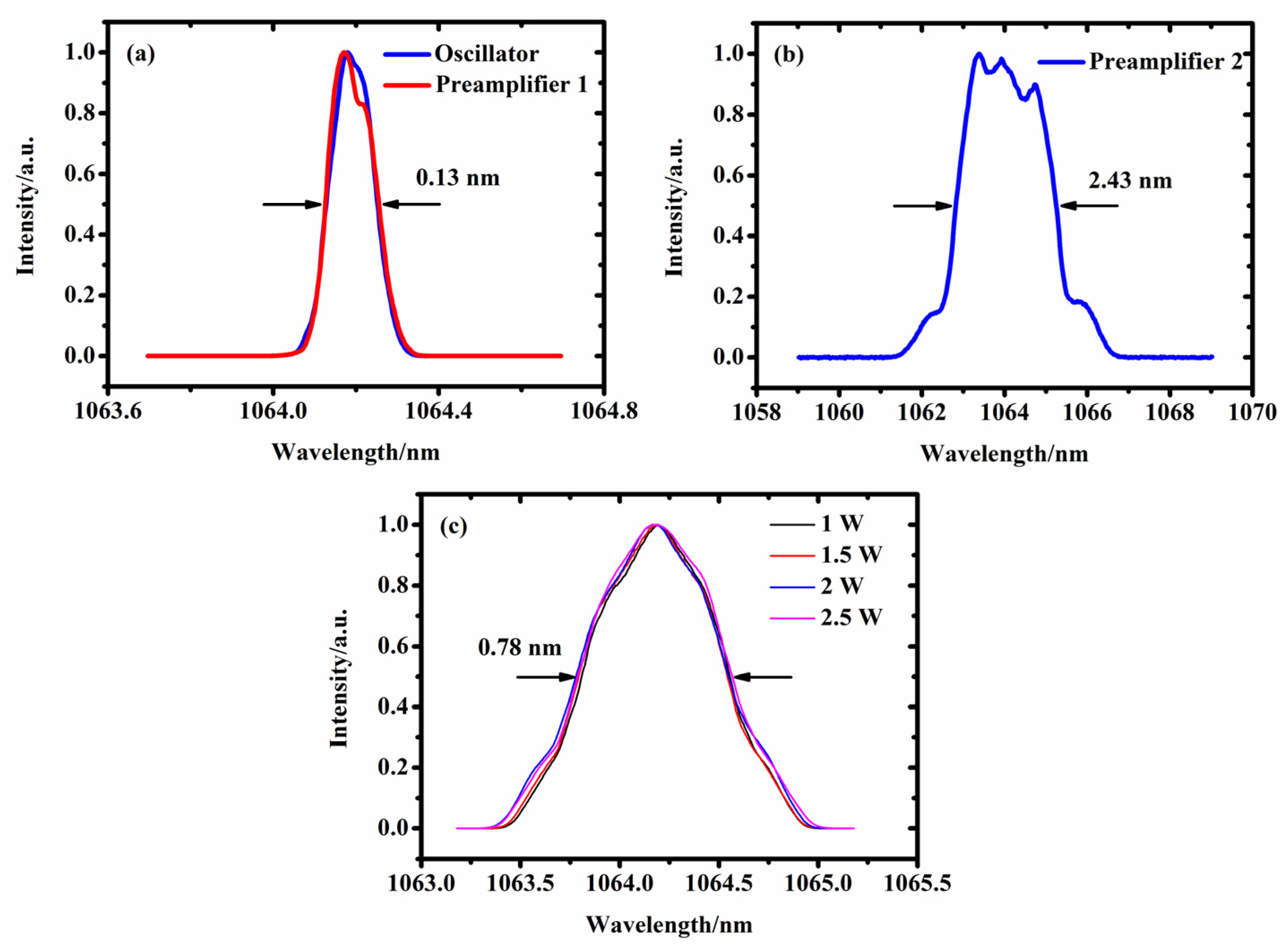
3.1. The Spectral Characteristics of Yb-Doped Fiber Master Oscillator

To match the gain linewidth of the fiber seed source and the Nd:YAG laser amplifier, we use a variety of fiber components to optimize output spectrum, including a fiber Bragg grating (FBG), a bandpass filter (BPF), and a pulse stretcher. The 3 dB bandwidth of FBG at 1064 nm is 0.3 nm. Figure 2a shows the output spectra of the mode-locked fiber laser oscillator and the single-mode fiber preamplifier (preamplifier 1), which were measured using an optical spectrum analyzer (YOKOGAWA-AQ6370D). It illustrates that the spectrum width of fiber laser can be optimized by using the filtering effect of FBG, such that the spectrum after mode-locked oscillator has no significant distortion. Then, the BPF is used to filter the amplified spontaneous emission and residual pump light at 976 nm. After the preamplifier 1, the output central wavelength is 1064.1 nm, and the 3 dB bandwidth is about 0.13 nm. For the Yb-doped all-fiber master oscillator without a pulse stretcher, the output spectrum of preamplifier 2 is shown in Figure 2b. During the power amplification, the power spectrum of preamplifier 1 is gradually broadened. However, the output spectrum of preamplifier 2 under the pump power of 1.5 W is sharply broadened, accompanied by distortion of the spectral profile. The 3 dB spectral bandwidth is broadened from ~0.12 nm to ~2.43 nm during amplification, and the peak of the spectrum moves to the short wavelength. The main reason of spectrum broadening is due to the self-phase modulation (SPM) effect.
SPM is a nonlinear effect produced by picosecond pulsed lasers in the amplification, especially in fiber lasers. The SPM-induced spectrum broadening is proportional to the maximum nonlinear phase shift Фmax, which is given by Фmax = γP0Leff, where γ is the nonlinear coefficient, P0 is the peak power of the incident pulses, and Leff is the effective length of the fiber [30]. Therefore, the nonlinear phase shift is proportional to the intensity of the incident pulses, which can be significant accumulated in high-peak-power lasers. The broadened spectral bandwidth is mismatched with the gain bandwidth of Nd:YAG, which reduces the amplification efficiency and limits the application of picosecond laser source. To solve the abovementioned problem, we decided to adopt a pulse stretcher to decrease the peak power of the incident pulses, thereby suppressing the degree of spectral broadening. The pulse stretcher is a single-mode passive fiber with a length of 1350 m, which has a group velocity dispersion (GVD) of 20 ps2·km−1 (β2) and a nonlinear coefficient of 0.91 W−1·km−1 (γ) at 1064 nm. Figure 3 shows the measured pulse temporal profiles before and after broadening. The temporal shape before stretching is Gaussian, and the pulse width is approximately 40 ps measured by autocorrelator (Femtochrome, FR-105XL), as shown in Figure 3a. The hundred-picosecond pulse width of all-fiber master oscillator is monitored by a high-speed photodiode (ALPHALAS, rise time: 35 ps) and a digital oscilloscope (LyCroy, bandwidth: 13 GHz). The pulse width is stretched from 40 ps to ~341 ps, which is shown in Figure 3b. The measured pulse shape is characterized by a steep front and a smooth back edge. This is because of the gain saturation effect, whereby the number of inversion particles consumed at the front edge is higher than that at the back edge. Hence, the phenomenon of larger front-edge gain and smaller back-edge gain appears. The corresponding variation in the spectrum distribution of the all-fiber master oscillator with pulse stretcher is shown in Figure 2c. It shows that, with the continuous increase in pump power, the 3 dB bandwidth is only slightly broadened to 0.78 nm, and the pulse energy is concentrated at the 1064.1 nm without multipeak structures. This is due to the combined effect of dispersion and SPM on pulse evolution, in which dispersion length (LD) and nonlinear length (LNL) provide very important length scales. They can be calculated by LD = T02/|β2| and LNL = 1/γP0, where T0 is the pulse width before stretching [31]. As a result, the dispersion length and the nonlinear length are about 80 km and 0.025 km, respectively. Obviously, when the length of single-mode fiber stretcher is 1.35 km (L), LNLLLD. Therefore, SPM plays a major role in the evolution of optical pulses, which leads to the changes in the pulse spectrum. Moreover, the single-mode fiber stretcher provides positive dispersion at 1064 nm. The laser pulse propagating in the normal dispersion regime can accelerate the pulse broadening via SPM effect. Furthermore, the peak power of the pulses decreases with the broadening of the pulse width; thus, the SPM-induced nonlinear phase shift is reduced. Therefore, Figure 2c shows that the broadening and distortion of the spectrum has been effectively suppressed with the use of the pulse stretcher. We inject the laser pulses from Figure 2c and Figure 3b into the QCW laser diode side-pumped Nd: YAG regenerative amplifier, and a pulse energy of 4 mJ at a repetition rate of 500 Hz is obtained. The main energy is concentrated at the central wavelength to match the gain bandwidth of the Nd:YAG, which is one of the main factors for achieving high-energy.

3.2. Compensation for Self-Focusing and Thermally Induced Birefringence Effect

First, it is worth noting that, for a millijoule-level laser amplifier, the nonuniformity of the input beam intensity will deteriorate the beam quality and even damage the optical components [32,33]. To avoid the self-focusing effect caused by the phase distortion of the laser beam during the transmission process, we performed beam shaping on the laser beam from the regenerative amplifier. The beam-shaping device consists of a SA and a SF1. The design of the SA adopts the grayscale coding mask method. The principle is to realize the modulation of the light transmission energy by adjusting the size and position of the microstructure of the light transmission unit at the edge of the SA, thereby achieving the purpose of beam shaping [34]. Subsequently, it is fabricated by photolithography and coating film. An enlarged view of the grayscale effect of the light-transmitting unit is shown in Figure 4, which shows the partial energy transmittance distribution. The result of the theoretical simulation is shown in Figure 5a, which depicts the intensity distribution of one-dimensional (1D) and two-dimensional (2D) views of the transverse field when the laser beam propagates 1 m via SA. The experimental measurement result is shown in Figure 5b, which is consistent with the theoretical result. The laser beam intensity of Nd:YAG regenerative amplifier is an ideal Gaussian distribution, which features high central intensity and relatively weak edge intensity. It is obvious from Figure 5 that the intensity distribution of the central part becomes relatively flat by using a soft-edge aperture. Therefore, SA can effectively reduce the central intensity of the laser beam and suppress the Fresnel diffraction. Then, we use the SF1 to relay-image the laser beam at SA to the image plane.
The Nd:YAG rod crystal has extremely high energy storage under high pump power, which will cause quite obvious thermal effects. The Nd:YAG gain medium is heated and cooled simultaneously during operation, thus forming a nonuniform radial temperature distribution. As a result, the temperature gradient and thermal strain photo-elastic effect generated inside the Nd:YAG crystal rod will cause the nonuniformity of the refractive index distribution, resulting in a thermally induced birefringence effect and thermal lens effect.
The thermally induced birefringence will lead to severe thermal depolarization and limit the output energy of picosecond laser source when the linearly polarized laser beam passes through the Nd:YAG crystal. Therefore, the compensation of the thermally induced birefringence is a significant issue that needs to be solved for the 10 mJ-level hundred-picosecond laser source, especially in a double-pass laser amplifier [35,36,37]. This is because, in the double-pass amplifier, the generated thermal depolarization power will be reflected back to the pre-stage regenerative amplifier, thereby damaging the optical components.
In our double-pass amplifier, a 45° Faraday rotator (FR4) is arranged between the Nd:YAG 2 and the HR3 to compensate for thermal depolarization. When a linearly polarized laser beam is transmitted through the same Nd:YAG 2 with a 90° polarization rotation, since the phases of the tangential and radial components of the polarization are exchanged, each point in the cross-section of the Nd:YAG 2 gain crystal has the same phase delay. In other words, when the laser beam passes through Nd:YAG 2 for the second time, each point in the propagation direction should have exactly the same beam distribution as the first time to ensure that the thermally induced depolarization effect is perfectly compensated.
However, the laser beam after the single-pass amplification will actually converge under the action of the thermal lens effect, such that it cannot be guaranteed that the double-pass amplification has the same transmission path. To solve this problem, we propose using a negative lens and a spatial filter relay-imaging device to compensate for the thermal lens effect and improve FR4’s ability to compensate for the thermal depolarization. When the laser beam passes through the optical path shown in Figure 6, the relay-imaging transmission conditions should meet the ABCD matrix. The transformation law of laser beam parameters after passing through an optical system can be expressed as follows [38]:
( x 1 θ 1 ) = ( A   B C   D ) ( x 1 θ 1 ) ,
where x and θ are the distance and included angle between the ray and the optical axis, respectively. Three spatial filter relay-imaging devices (SF1, SF2, and SF3) are used in this laser source. We set the image plane of SF on these planes, which are easy to be damaged or need high beam quality, such as HR3, the center of Nd:YAG 2, and the detection surface of beam quality analyzer. In addition, it is necessary to consider the influence of transmissive elements on the relay-imaging distance, including Nd:YAG 2, and terbium glass crystal in FR4. In order to meet the relay-imaging law of the near field and far field, the ABCD matrix can be expressed as follows:
( A B C D ) = ( 1 d 2 + d 3 + d 4 0 1 ) ( 1 l 2 n 0 1 ) ( 1 0 1 f 1 ) ( 1 2 f 0 1 ) ( 1 0 1 f 1 ) ( 1 d 1 0 1 ) ,
( A B C D ) = ( 1 d 6 l 1 0 1 ) ( 1 l 1 n 1 0 1 ) ( 1 0 1 f 1 ) ( 1 2 f 0 1 ) ( 1 0 1 f 1 ) ( 1 l 2 n 0 1 ) ( 1 d 5 0 1 ) ,
( A B C D ) = ( 1 d 8 0 1 ) ( 1 0 1 f 1 ) ( 1 2 f 0 1 ) ( 1 0 1 f 1 ) ( 1 l 2 n 0 1 ) ( 1 d 4 + d 7 0 1 ) ,
( A B C D ) = ( 1 f 0 1 ) ( 1 0 1 f 1 ) ( 1 d 2 + d 3 + d 4 + d 5 0 1 ) ( 1 l n 0 1 ) ( 1 0 1 f 1 ) ( 1 f 0 1 ) ,
where l = 105 mm and l1 = 20 mm are the lengths of Nd:YAG 2 and terbium glass crystal, and their refractive indices are n = 1.82 and n1 = 1.72, respectively. F = 200 mm is the focal length of the plano-convex lens in the spatial filter relay-imaging device. Among them, the values of d1 to d5 can be calculated using the matrix. When the laser beam passes FR4 twice, because the polarization plane is rotated by 90°, the phases of the tangential component and radial component are swapped, and the included angle between the ray and the optical axis alters from θ1 to −θ1. SF2 has an object-image ratio of 1:1, and the value of x is invariant. Furthermore, a negative lens L1 with a focal length of −300 mm is inserted to compensate for the thermal lens effect of Nd:YAG 2. The Nd:YAG double-pass amplifier with this structure can obtain ideal thermal birefringence compensation. We simulate the change of the mode field diameter of the Nd:YAG double-pass amplifier, as shown in the inset in Figure 6. This illustrates that the principle of laser beam transmission is to maintain the propagation of parallel light as much as possible, and the laser spot diameter in the center of the Nd:YAG 2 is the largest.
After being amplified from the regenerative amplifier, we accurately control the incident single pulse energy, and SA introduces additional energy loss. Finally, the 0.8 mJ hundred-picosecond pluses are injected to QCW laser diode side-pumped Nd:YAG double-pass amplifier. The Nd:YAG 2 is operated at a pump power 420 W, and a total pulse energy of 14.8 mJ is obtained. The output power is detected behind the HWP5 and PBS, which is reduced to 14.58 mJ. Therefore, the depolarization rate is 1.5%. The main reason for not achieving complete compensation of thermally induced depolarization is the deviation of the focal length of the L1 and the misalignment of the optical path.

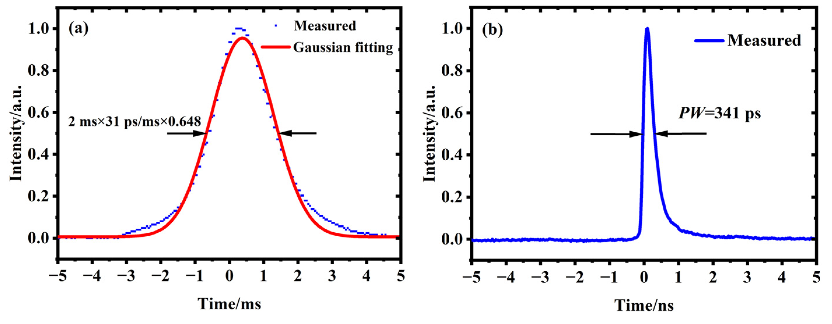
3.3. The Output Characteristics of Fiber–Solid Hybrid Laser Source

Figure 7a shows the output energy of the Nd:YAG double-pass amplifier. The all-fiber master oscillator delivers pulse energy of 9.6 nJ and pulse width of 341 ps at a repetition rate of 28.49 MHz and a 3 dB spectral bandwidth of 0.78 nm. The seed pulses are amplified to 4 mJ at a repetition rate of 500 Hz by a QCW side-pumped Nd:YAG regenerative amplifier. By precisely controlling the energy of the incident pulses, these pulses are further amplified to 14.58 mJ by a QCW side-pumped Nd:YAG double-pass amplifier. The corresponding magnification is 18.2. By using a negative lens to compensate the thermal lens effect, 90° polarization rotation to compensate for thermal birefringence, and spatial filter to achieve relay image, the depolarization loss can be controlled to below 1.5%. The output power stability was tested over 8 h, and an RMS power fluctuation of 1.9% was achieved, as shown in the illustration of Figure 7a. Figure 7b shows the spectrum distributions of the regenerative amplifier and double-pass amplifier. The pulse stretcher significantly suppresses the spectral broadening, and the relatively narrow spectral width of 0.78 nm allows efficient energy amplification in Nd:YAG amplifier with a gain bandwidth of 0.45 nm. The 3 dB bandwidth of the regenerative amplifier is narrowed from 0.78 nm to 0.35 nm due to the gain-narrowing effect. After being double-pass amplified, the 3 dB spectrum bandwidth is slightly broadened to 0.47 nm. This is because SPM-induced new spectral components to be generated during high peak power double-pass amplification, resulting in the broadening of spectrum and narrowing of pulse width. Therefore, the pulse width of the Nd:YAG double-pass amplifier is narrowed to 228 ps, as shown in Figure 7c. The beam quality of the laser source is recorded by a beam quality analyzer (Ophir-Spiricon, M2-200). When the laser source delivers an output repetition frequency of 500 Hz and a pulse width of 228 ps at a central wavelength of 1064.1 nm, the intensity distributions of the far field are as shown in Figure 8. The beam quality factors are Mx2 = 1.49 in the x direction and My2 = 1.51 in the y direction at the output energy of 14.58 mJ. It is evident that the high beam quality benefits from the effective compensation for the thermal effects.

3.4. The Theoretical Simulation of Hundred-Picosecond Laser Ablation

Here, to test this hundred-picosecond laser source, we carried out a theoretical numerical simulation of picosecond single-pulse laser ablation of metallic copper material.
First, a geometric model was created using Comsol software, which was simplified to a 2D axisymmetric form for computational processing. Then, the mapping mesh was divided into appropriate densities to improve the computational accuracy and reduce the computational time. Finally, the simulation of the physical field was completed by solving the partial differential equations. For the interaction of picosecond pulsed laser with metallic copper, the ablation mechanism was a nonthermal equilibrium ablation process. To characterize this nonequilibrium process, the time for the electrons to interact with the lattice and, thus, complete the electron-lattice energy transfer could not be neglected. This means that the time required for the electron-lattice relaxation process needed to be taken into account. In this case, the electron temperature (Te) and lattice temperature (Tl) were not equal since the pulse duration was on the same timescale as the relaxation time [39]. From this, we established a two-temperature diffusion model to describe the one-dimensional heat transfer in the electron system and the lattice system. We set the initial conditions (Te = Tl = 300 K) and boundary conditions. The two-temperature equations were solved using the finite element method, thereby obtaining the variation law of the electron and lattice temperatures in the time domain. Figure 9 plots the temporal evolution of electron and lattice temperatures at the front surface of metallic copper heated by the 228 ps laser pulse with a pulse energy of 14.58 mJ. In spite of the relatively flat intensity distribution at the center of the laser beam from this hundred-picosecond laser source, it still exhibited Gaussian beam characteristics when converging on the surface of a metallic copper target via a lens with a focal length of 100 mm. The spatial profile of the Gaussian beam output from this laser source was measured using a beam quality analyzer, and the focal spot diameter of ~35.72 μm was determined by the transformation relationship of the Gaussian beam waist. The inset of Figure 9 illustrates a local enlarged view of the electron and lattice temporal evolution. As depicted in the inset, the electron temperature increased sharply to ~11,499 K under this hundred-picosecond laser irradiation. Simultaneously, the lattice temperature also increased during the electron-lattice energy transfer. At the end of a laser pulse, the electron temperature stopped growing. Moreover, the energy transfer induced a decrease in the electron temperature and a continued increase in the lattice temperature. Correspondingly, the maximum temperature of the lattice reached ~11,496 K (t = 0.78 ns). Eventually, the temperatures of the electron and the lattice reached equilibrium. Figure 10 displays the final temperature field distribution of the copper target, thus clearly observing that the temperature was higher at the center of the laser focus and lower near the laser edge. The main reason for this was the Gaussian distribution of the picosecond laser power density in the spatial domain. The color legends on the left and right represent the temperatures of the isopleths and isosurfaces, respectively. It can be seen that the temperature at the laser focus was up to ~1.15 × 10⁴ K when the laser irradiation time was 1 ns. Moreover, the temperature of the isopleths was accompanied by a significant variation. The simulation results prove that the ablation temperature was much higher than the evaporation temperature of copper, 2840 K [40]. Therefore, the homemade millijoule-level hundred-picosecond laser is able to meet the material removal requirements for copper. The simulated ablation morphologies are shown in Figure 11. In the initial stage, the laser only melts the surface depth of the material, as shown in Figure 11a (t = 0.22 ns). As the irradiation time increases (Figure 11a,b), the material at the center of the focused spot begins to vaporize, and the vaporized splitting mixture is ejected from the surface. The material is gradually vaporized and removed accompanied by the ejection of splitting matter, resulting in the formation of a micropore. A micron-sized hole was formed when the irradiation time increased to 0.46 ns, as illustrated in Figure 11c. Subsequently, the ablation depth varied with increasing irradiation time, but not linearly (Figure 11d–h). The micropore was close to the final etched morphology when the irradiation time increased to 0.82 ns, as shown in Figure 11f. The final etched depth of copper was approximately 7.86 μm. The simulation results adequately demonstrate the rapid temperature change of the copper material under the action of the hundred-picosecond laser. This means that the etching process of the material was basically finished within a very short time after the action of the 228 ps pulse laser. It is evident that the etch formation time was longer than the pulse duration. The possible reason for this is the heat conduction losses of the material. In our theoretical simulations, the power density of the pulsed laser source was 72.8 × 10⁵ W·cm−2. When the power density of the incident light is below 106–108 W·cm−2, most of the energy is needed to heat the whole material; thus, most of the energy will be lost in this process. In addition, the thermal conductivity of copper at 300 K is 4.01 W·cm−1·° C−1, which is higher than that of other metallic materials. This means that only a small portion of the energy is used to evaporate the copper [41]. Therefore, this etching process requires a longer irradiation time.
In the early stages of the micro-hole formation process, the ablation depth is usually increasing rapidly. However, the hole depth is not changed in the later stages (after ~0.82 ns, as shown in Figure 11g–h). This can be explained by two factors. First, the focused high-peak-power-density laser beam is initially capable of removing large amounts of material. However, as the depth of ablation increases, the peak power density of the laser beam decreases due to the defocused beam, thus reducing the rate of material removal. Second, a large number of free electrons are generated due to multiphoton ionization and avalanche ionization effects under the hundred-picosecond laser irradiation, resulting in the formation of a dense plasma on the target surface. In general, the formed plasma can further absorb the energy of the incident laser via the inverse Bremsstrahlung (IB) effect, thereby reducing the energy of the laser beam delivered to the target [42].
To further corroborate the plasma generation under this hundred-picosecond laser irradiation, in accordance with the hydrodynamic theory, three first-order quasi-linear partial differential equations were solved separately using the finite element method [43,44]. Accordingly, we obtained the two-dimensional spatial distribution of the free electron concentration within the 100 ps time range, as demonstrated in Figure 12. In Figure 12, the color legend on the right represents the relative intensity of the free electron concentration. The z-axis and the r-axis represent the distance perpendicular to the target surface and the distance from the laser beam axis, respectively. The simulation results show that a large number of electrons were ejected outward from the target surface along the z-axis direction for laser irradiation times in the range of 0.22–1 ns; thus, the concentration of electrons increased continuously. In addition, there was a large difference in the free electron concentration at the laser focus and at the edge, which was attributed mainly to the Gaussian distribution of the picosecond laser peak power density in the r-axis direction. From the results of the simulation, we can confirm the formation of plasma corresponding to the simulation results of the laser ablation depth. Therefore, it can be determined that, for a millijoule-level hundred-picosecond laser radiation source, both laser-induced thermal damage and laser-induced plasma expansion play an important role in energy transfer during laser material processing.

4. Conclusions

In summary, we developed a 10 mJ-level fiber–solid hybrid hundred-picosecond laser source with a stable performance and compact structure. It consists of an all-fiber master oscillator, a QCW side-pumped Nd:YAG regenerative amplifier, and a Nd:YAG double-pass amplifier. In this laser system, pulse stretcher, beam shaping, and thermal effect compensation are used to realize high-energy hundred-picosecond laser output. First of all, we use fiber components such as a fiber Bragg grating, bandpass filter, and fiber stretcher to effectively suppress nonlinear effects, thereby controlling the width of the spectrum, and achieving effective matching of the gain linewidth of fiber and the solid amplifier. Then, we theoretically and experimentally study the self-focusing effect and thermal effect compensation in the solid-state Nd:YAG laser amplifier. With this system, we obtain a single pulse energy of 14.58 mJ and a pulse width of 228 ps at a repetition rate of 500 Hz. It has a 3 dB spectral width of 0.47 nm at 1064.1 nm. The beam quality factors are 1.49 and 1.51 along the x- and y-axis directions, respectively. Lastly, we theoretically simulated the laser ablation process of metallic copper material, thus confirming the practicability of this hundred-picosecond laser source. This compact laser source is capable of generating millijoule-level hundred-picosecond laser pulses, which is perfect light source for studying thermal damage and plasma damage of the laser-induced materials. Due to the advantages of the interaction between the millijoule-level hundred-picosecond laser and the materials, we are eager to further enhance the output characteristics of laser system and apply it in industrial processing and laser-induced damage.

Author Contributions

T.W. designed the study, conducted the experiments, contributed to the data analysis and discussion of the results, and wrote the manuscript; J.W., M.Z., H.P. and J.Z. participated in the numerical simulation of the theory; G.Q., Y.T. and H.C. provided theoretical ideas and revised the manuscript. All authors have read and agreed to the published version of the manuscript.

Funding

This work was supported by the Natural Science Foundation of Jilin Province (20200201257JC) and the Key Scientific and Technological Research Project of Jilin Provincial Department of Science and Technology (20190303108SF).

Institutional Review Board Statement

Not applicable.

Informed Consent Statement

Not applicable.

Data Availability Statement

Not applicable.

Acknowledgments

The authors thank Beijing University of Technology for providing experimental support with the picosecond laser source.

Conflicts of Interest

The authors declare no conflict of interest.

References

  1. Bai, Z.X.; Wang, Y.L.; Lu, Z.W.; Jiang, L.; Yuan, H.; Liu, Z.H. Demonstration of an ultraviolet stimulated Brillouin scattering pulse compressed hundred picosecond laser in LiB3O5 crystals. J. Opt. 2017, 19, 085502. [Google Scholar] [CrossRef]
  2. Chen, H.; Deng, L.M.; Duan, J.; Zeng, X.Y. Picosecond laser welding of glasses with a large gap by a rapid oscillating scan. Opt. Lett. 2019, 44, 2570–2573. [Google Scholar] [CrossRef] [PubMed]
  3. Ly, S.; Shen, N.; Negres, R.A.; Carr, C.W.; Alessi, D.A.; Bude, J.D.; Rigatti, A.; Laurence, T.A. The role of defects in laser-induced modifications of silica coatings and fused silica using picosecond pulses at 1053 nm: I. Damage morphology. Opt. Express 2017, 25, 15161–15178. [Google Scholar] [CrossRef] [PubMed]
  4. Žemaitis, A.; Gaidys, M.; Brikas, M.; Gečys, P.; Račiukaitis, G.; Gedvilas, M. Advanced laser scanning for highly-efficient ablation and ultrafast surface structuring: Experiment and model. Sci. Rep. 2018, 8, 17376. [Google Scholar] [CrossRef]
  5. Hou, Z.Y.; Liu, L.J.; Fang, Z.; Yang, L.; Ya, D.X.; Wang, X.Y.; Xu, D.G.; Chen, C.T. High-power 266 nm laser generation with a NaSr3Be3B3O9F4 crystal. Opt. Lett. 2018, 43, 5599–5602. [Google Scholar] [CrossRef]
  6. Galletti, M.; Oliveira, P.; Galimberti, M.; Ahmad, M.; Archipovaite, G.; Booth, N.; Dilworth, E.; Frackiewicz, A.; Winstone, T.; Musgrave, I. Ultra-broadband all-OPCPA petawatt facility fully based on LBO. High Power Laser Sci. Eng. 2020, 8, e31. [Google Scholar] [CrossRef]
  7. Long, M.L.; Zhang, Z.P.; Chen, Z.E.; Zhang, H.F.; Deng, H.R.; Wu, Z.B.; Meng, W.D. A picosecond laser at 1 kHz with dual-length of regenerative amplifier for the SLR in the daytime. Optik 2018, 171, 833–838. [Google Scholar] [CrossRef]
  8. Zhang, Z.P.; Zhang, H.F.; Long, M.L.; Deng, H.R.; Wu, Z.B.; Meng, W.D. High precision space debris laser ranging with 4.2 W double-pulse picosecond laser at 1 kHz in 532 nm. Optik 2019, 179, 691–699. [Google Scholar] [CrossRef]
  9. Wang, K.X.; Li, P.X.; Yu, X.Y.; Yao, C.F.; Wang, T.T. Experimental study on CMOS and materials irradiated by hundred-picosecond pulse laser with high repetition rate. Proc. SPIE 2020, 1154407, 15–23. [Google Scholar]
  10. Liu, X.S.; Jia, W.Z.; Yang, S.; He, H.; Liu, Y.Q.; Yan, A.R.; Wang, Z.Y. A high pulse energy single-pass picosecond master oscillator power amplifier system with output power 35.7 W. Opt. Laser Technol. 2020, 121, 105782. [Google Scholar] [CrossRef]
  11. Liu, X.S.; Jia, W.Z.; Song, Y.H.; Yang, S.; Liu, S.; Liu, Y.Q.; Yan, A.R.; Wang, Z.Y. High energy, high brightness picosecond master oscillator power amplifier with output power 65.5 W. Opt. Express 2020, 28, 8016–8026. [Google Scholar] [CrossRef] [PubMed]
  12. Ma, N.; Chen, M.; Yang, C.; Lu, S.; Zhang, X.; Du, X.B. High-efficiency 50W burst-mode hundred picosecond green laser. High Power Laser Sci. Eng. 2020, 8, e1. [Google Scholar] [CrossRef]
  13. Zhou, Y.P.; Li, X.D.; Wu, W.T.; Jiang, Y.G.; Fan, R.W.; Chen, D.Y.; Yan, R.P. 500 Hz, 47.1 mJ, sub-nanosecond MOPA laser system. Opt. Laser Technol. 2021, 134, 106592. [Google Scholar] [CrossRef]
  14. Noom, D.W.E.; Witte, S.; Morgenweg, J.; Altmann, R.K.; Eikema, K.S.E. High-energy, high- repetition-rate picosecond pulses from a quasi-CW diode-pumped Nd:YAG system. Opt. Lett. 2013, 38, 3021–3023. [Google Scholar] [CrossRef]
  15. Huang, Y.T.; Zhang, H.B.; Yan, X.C.; Guo, G.Y.; Bai, Z.N.; Lin, W.R.; Kang, Z.J.; Qiu, J.S.; Zhao, T.Z.; Fan, Z.W. High-Brightness 100 Hz/363 mJ Picosecond Nd:YAG Laser System for Ultra-Remote Laser Ranging. IEEE J. Quantum Electron. 2020, 56, 1700310. [Google Scholar] [CrossRef]
  16. Huang, L.; Ma, P.F.; Tao, R.M.; Shi, C.; Wang, X.L.; Zhou, P. 11.5 kW ytterbium-doped single- transverse-mode linearly polarized monolithic fiber master oscillator power amplifier. Appl. Opt. 2015, 54, 2880–2884. [Google Scholar] [CrossRef]
  17. Yu, Z.H.; Shi, W.; Dong, X.Z.; Li, J.H.; Zhao, Y.Z.; Liu, H.X. 110 W all-fiber picosecond master oscillator power amplifier based on large-core-diameter ytterbium-doped fiber. Appl. Opt. 2016, 55, 4119–4122. [Google Scholar] [CrossRef]
  18. Saraceno, C.J.; Sutter, D.; Metzger, T.; Ahmed, M.A. The amazing progress of high-power ultrafast thin-disk lasers. J. Eur. Opt. Soc.-Rapid Publ. 2019, 15, 15. [Google Scholar] [CrossRef]
  19. Smrz, M.; Muzik, J.; Stepankova, D.; Turcicova, H.; Novak, O.; Chyla, M.; Hauschwitz, P.; Brajer, J.; Kubat, J.; Todorov, F.; et al. Picosecond thin-disk laser platform PERLA for multi-beam micromachining. OSA Contin. 2021, 4, 940–952. [Google Scholar] [CrossRef]
  20. Dong, X.Y.; Li, P.X.; Li, S.; Wang, T.T.; Yang, M. High Beam Quality Fiber-Solid Hybrid Innoslab Picosecond Amplifier with High Repetition Rate. Chin. J. Lasers 2021, 48, 1701004. [Google Scholar]
  21. Shi, B.N.; Li, J.T.; Ye, S.; Nie, H.K.; Yang, K.J.; He, J.L.; Li, T.; Zhang, B.T. Modified Frantz-Nodvik equation and numerical simulation of a high-power Innoslab picosecond laser amplifier. Opt. Express 2022, 30, 11026–11035. [Google Scholar] [CrossRef] [PubMed]
  22. Dong, X.Y.; Li, P.X.; Li, S.; Wang, D.S. High gain fiber-solid hybrid double-passing end-pumped Nd:YVO4 picosecond amplifier with high beam quality. Chin. Phys. B 2020, 29, 054207. [Google Scholar] [CrossRef]
  23. Liu, M.Z.; Liu, M.L.; Yan, W.; Yang, D.W.; Wang, L.S.; Sun, S.S.; Jia, Z.Q.; Zhai, R.Z.; Wang, Y.; Zhao, K. Fiber-solid hybrid end-pumped Nd:YVO4 picosecond amplifier with high beam quality. Laser Phys. 2021, 31, 065801. [Google Scholar] [CrossRef]
  24. Lv, X.L.; Su, H.P.; Peng, Y.J.; Leng, Y.X. High-energy, quasi-CW 355 nm UV pulses generation from a diode pumped sub-nanosecond Nd:YAG system. Proc. SPIE 2018, 10896, AM6A-20. [Google Scholar]
  25. Honig, J.; Halpin, J.; Browning, D.; Crane, J.; Hackel, R.; Henesian, M.; Peterson, J.; Ravizza, D.; Wennberg, T.; Rieger, H.; et al. Diode-pumped Nd:YAG laser with 38 W average power and user-selectable, flat-in-time subnanosecond pulses. Appl. Opt. 2007, 46, 3269–3275. [Google Scholar] [CrossRef]
  26. Wang, C.; Wei, H.; Wang, J.F.; Jiang, Y.E.; Fan, W.; Li, X.C. Laser diode pumped Nd:YAG laser with high repetition and high average power. Acta Phys. Sin. 2014, 63, 224204. [Google Scholar] [CrossRef]
  27. Lv, X.L.; Peng, Y.J.; Wang, W.Y.; Zhao, Y.A.; Zhu, X.Y.; Leng, Y.X. High-energy, high-repetition-rate ultraviolet pulses from an efficiency-enhanced, frequency-tripled laser. High Power Laser Sci. Eng. 2021, 9, e38. [Google Scholar]
  28. Michailovas, K.; Baltuska, A.; Pugzlys, A.; Smilgevicius, V.; Michailovas, A.; Zaukevicius, A.; Danilevicius, R.; Frankinas, S.; Rusteika, N. Combined Yb/Nd driver for optical parametric chirped pulse amplifiers. Opt. Express 2016, 24, 22261–22271. [Google Scholar] [CrossRef]
  29. Lian, F.Q.; Fan, Z.W.; Bai, Z.A.; Li, X.H.; Wang, Q.J. Optimization of spectral distortion in a ytterbium-doped mode-locked fiber laser system. Photon. Res. 2015, 3, 129–132. [Google Scholar] [CrossRef]
  30. Yang, M.; Li, P.X.; Li, S.; Xiong, W.H.; Wang, K.X.; Yao, C.F.; Wang, D.S. 54 W nanosecond Yb-doped all-fiber amplifier at ultra-high repetition rate (tens of MHz) based on mode-locked fiber oscillator and single-mode fiber stretcher. Laser Phys. 2021, 31, 025101. [Google Scholar] [CrossRef]
  31. Agrawal, G.P. Nonlinear Fiber Optics, 5th ed.; Beijing World Publishing Corporation: Beijing, China, 2015. [Google Scholar]
  32. Sizova, I.; Moskalev, T.; Mikheev, L. Laser beam shaping with circular serrated apertures. I. Spatial filtering. Appl. Opt. 2019, 58, 4905–4909. [Google Scholar] [CrossRef] [PubMed]
  33. Sizova, I.; Moskalev, T.; Mikheev, L. Laser beam shaping with circular serrated apertures. II. Theory of the beam profile formation. Appl. Opt. 2019, 58, 4910–4917. [Google Scholar] [CrossRef]
  34. Wu, C.C.; Gao, F.H.; Huang, D.Q.; Yang, Z.J.; Guo, Y.K.; Du, J.L.; Zhang, Y.X. Design and fabrication of a slot aperture with softened edge based on gray-tone coding method. Microelectron. Eng. 2011, 88, 2180–2183. [Google Scholar] [CrossRef]
  35. Ostermeyer, M.; Klemz, G.; Kubina, P.; Menzel, R. Quasi-continuous-wave birefringence- compensated single- and double-rod Nd:YAG lasers. Appl. Opt. 2002, 41, 7573–7582. [Google Scholar] [CrossRef]
  36. Jeong, J.; Cho, S.; Kim, T.; Yu, T.J. Numerical Study of a Thermally-compensated High-energy Double-pass Nd:YAG Amplifier Design. J. Korean Phys. Soc. 2016, 68, 653–657. [Google Scholar] [CrossRef]
  37. Yang, C.; Peng, H.P.; Chen, M.; Lu, S.; Ma, N. Effect of the azimuthal gradient of the thermal load on the depolarization of cylindrical vector beams propagating in a side non-uniformly pumped isotropic medium. Results Phys. 2019, 12, 2069–2074. [Google Scholar] [CrossRef]
  38. Yang, S.S.; Cui, Z.J.; Sun, Z.M.; Zhang, P.; Liu, D. Compact 50 W All-Solid-State Picosecond Laser System at 1 kHz. Appl. Sci. 2020, 10, 6891. [Google Scholar] [CrossRef]
  39. Ren, Y.P.; Chen, J.K.; Zhang, Y.W. Optical properties and thermal response of copper films induced by ultrashort-pulsed lasers. J. Appl. Phys. 2011, 110, 113102. [Google Scholar] [CrossRef]
  40. Ji, L.P.; Song, Z.Y.; Sun, Y.P.; Wang, X.S.; Li, C.Y. Single-short picosecond laser ablation of copper based on Comsol. Laser Optoelectron. Prog. 2018, 55, 101402. [Google Scholar]
  41. Jia, X.; Zhao, X. Numerical study of material decomposition in ultrafast laser interaction with metals. Appl. Surf. Sci. 2019, 463, 781–790. [Google Scholar] [CrossRef]
  42. Shin, J.; Mazumder, J. Plasma diagnostics using optical emission spectroscopy in laser drilling process. J. Laser Appl. 2016, 28, 022008. [Google Scholar] [CrossRef]
  43. Wang, T.T.; Li, P.X.; Yu, X.Y.; Wang, K.X.; Wang, D.S.; Zhang, Y.F.; Li, C.Y. High-energy hundred-picosecond fiber-solid hybrid laser and its application in laser-induced damage in PIN photodiode. Laser Phys. 2020, 30, 036004. [Google Scholar] [CrossRef]
  44. Wang, K.X.; Yu, X.Y.; Li, P.X.; Wang, T.T.; Zhang, Y.F.; Li, C.Y. Laser-induced damage in a silicon-based photodiode by MHz picosecond laser. Laser Phys. 2020, 30, 076002. [Google Scholar] [CrossRef]
Figure 1. Schematic diagram of fiber–solid hybrid master oscillator power amplifier system.
Applsci 12 09621 g001
Figure 2. Spectrum distribution of (a) oscillator and preamplifier 1, (b) preamplifier 2 at pump power of 1.5 W without a pulse stretcher, and (c) preamplifier 2 at different pump powers with a pulse stretcher.
Applsci 12 09621 g002
Figure 3. Temporal pulse profile of (a) before and (b) after broadening.
Applsci 12 09621 g003
Figure 4. The design layout of grayscale coding mask (enlarged view).
Applsci 12 09621 g004
Figure 5. (a) Theoretical simulation, and (b) experimental measurement result of 1D and 2D intensity distribution at 1 m behind the SA.
Applsci 12 09621 g005aApplsci 12 09621 g005b
Figure 6. Schematic diagram of image relaying optical path of double-pass amplifier.
Applsci 12 09621 g006
Figure 7. (a) Output energy and magnification of the Nd:YAG double-pass amplifier. The inset shows the power stability of the laser source in 8 h. (b) Spectrum distribution of regenerative amplifier and double-pass amplifier. (c) Temporal profiles of the regenerative amplifier and double-pass amplifier.
Applsci 12 09621 g007aApplsci 12 09621 g007b
Figure 8. Beam quality of the laser source.
Applsci 12 09621 g008
Figure 9. Variation of electron and lattice temperatures in the time domain; the inset shows a local enlarged view.
Applsci 12 09621 g009
Figure 10. Simulation results of the temperature field distribution at an irradiation time of 1 ns.
Applsci 12 09621 g010
Figure 11. Simulation results of etched morphology at different moments.
Applsci 12 09621 g011
Figure 12. Simulation results of free electron concentration.
Applsci 12 09621 g012
Publisher’s Note: MDPI stays neutral with regard to jurisdictional claims in published maps and institutional affiliations.

