1. Introduction
Energy consumption for heating, cooling, ventilation, and air conditioning corresponds to 35% of the energy consumption of the entire building [
1]. Considering the fact that energy resources are decreasing day by day, the necessity for reducing this energy spent on heating and cooling indoor environments has emerged. In addition, devices used for heating and cooling have negative effects on the environment due to their emission values. In this direction, it is seen that the use of renewable energy sources in the world has increased in recent years and this trend is also applied to heating and cooling systems for both energy efficiency and environmental benefit [
2,
3]. One of the renewable energy source devices used for cooling is evaporative coolers. Evaporative coolers (EC) are environmentally friendly air conditioning systems with low energy consumption and cooling the incoming air based on the evaporation of water at every temperature. However, conventional ECs are more effective and efficient in hot and low humidity areas [
4]. The most effective method is based on Dew-Point Cooling (DPC) for ECs that differ depending on heat exchanger structures, geometries air supply structures, and cooling strategies [
5]. This process allows air to be cooled below its wet-bulb temperature and reach the dew-point temperature of the treated air. DPC allows for generating energy savings in comparison to the traditional EC in dry climates [
6]. Theoretical information about DPC systems, modeling methods, performance studies, and DPC applications were gathered by Zhu et al. [
7]. Readers can refer to this article for more detailed information. The advantages of DPCs in the fields of energy consumption, expansion of application area, and environmental protection are tried to be increased by combining them with different designs and cooling techniques. One of them is the use of desiccant cooling technology and ECs together. Desiccant cooling systems are heat-operated cooling units and can be used as an alternative to conventional vapor compression and absorption cooling systems [
8,
9]. These systems, which are based on the operation of a rotary dehumidifier that dehumidifies the air inside, are combined with the cooling performance of ECs to increase the cooling performance in more humid environments [
10]. The performances of the desiccant evaporative cooling system are investigated in many papers [
11,
12,
13,
14,
15,
16] and they showed and analyzed the effects of system parameters on the thermal-comfort conditions, overall performance of the cooling system, and energy efficiency for different geometries, structures, and evaporative cooling techniques. Systems where DPCs are combined with desiccant cooling systems cause both the dehumidification performance of DPCs to increase and the cooling performance of desiccant cooling systems to increase. Lui and Jeong [
17] investigated energy saving and system performances for systems with direct, indirect, and dew-point evaporative coolers and liquid desiccant cooling systems. On the other hand, Pandelis et al. [
18] have developed a new cooler in which DPCs are used as pre- and post-coolers and dehumidification is provided by a desiccant wheel, and their performance is examined both numerically and experimentally.
In addition to geometric and structural changes, another method of increasing the performance and energy efficiency of coolers in which DPC systems are used is developing controllers for coolers that take into account environmental and operational conditions. While the comfort of the environment desired to be conditioned with active control is provided faster, energy savings are also achieved by operating the cooler actuators more efficiently. There are many studies in the literature related to the control of conventional air conditioning systems [
19,
20,
21,
22]. In these papers, where temperature and relative humidity control is provided according to the building and environmental conditions, the room/building comfort is brought to the desired conditions quickly and focused on energy efficiency. However, there are very few studies in the literature on temperature and humidity control about evaporative cooling systems and basic control methods (ON/OFF, P, PI, etc.) applied to reduce energy consumption without reducing room comfort in these studies. As can be seen from the studies in the literature, the best energy-saving application for DPC systems is the control of the speeds of the fans used for air intake–exhaust according to the conditions. Yan et al. [
23] investigated developed capacity and improved controllers’ performances of the three evaporator systems for indoor temperature and humidity control. The proportional–integral (PI) [
24] and high–low speed control strategies [
25,
26] are used to provide energy efficiency for the Indirect EC with the control of the fans at a variable speed. Energy efficiency can be achieved by regulating the operations and working speed of the water pump, which is another actuator. Hossein et al. [
27] achieved energy savings for the direct EC system by adjusting the operation times of the water pump. By using these control strategies, it is seen that energy efficiency is increased by between 15% and 30% for DPC systems. It shows that the comfort conditions can be achieved faster and with less energy consumption by regulating the operation of the actuators in the cooler.
In this study, an independent temperature and relative humidity control strategy is developed for the extra cooling performance with an extra energy saving of pre-cooled desiccant-wheel-based dew-point evaporative cooling system. This controller strategy increases the environmental compatibility of the cooling system, cooling performance, and energy efficiency. For this purpose, the control strategy is based on the proportional (P) control technique, in which the speeds of the actuators (fans and desiccant wheel) are adjusted according to the environment and room conditions throughout the process. The energy consumption of the system has been tried to be minimized by adding different operating modes for each actuator and adding extra automatic run/stop property in the control strategy. The results show that the temperature and relative humidity of the room reach the set values quickly and robustly, despite the disturbance effects such as heat gains from windows/roof/doors and humans. During this process, the proposed control strategy shows an extra energy-saving performance than the classical ON/OFF control method.
2. Desiccant Air-Cooling-Based Evaporative Cooler System
Conventional DPC systems are very efficient in operation in dry climates, but cooling efficiency drops significantly when operating in humid climates. However, the disadvantages of traditional DPC systems such as the use of extra water, lack of independent humidity and temperature control, and the great influence of operating conditions on cooling performance can be overcome with new cooling system designs. The high cooling performance of pre-cooled desiccant air cooling systems has been proven by Pandelidis et al. [
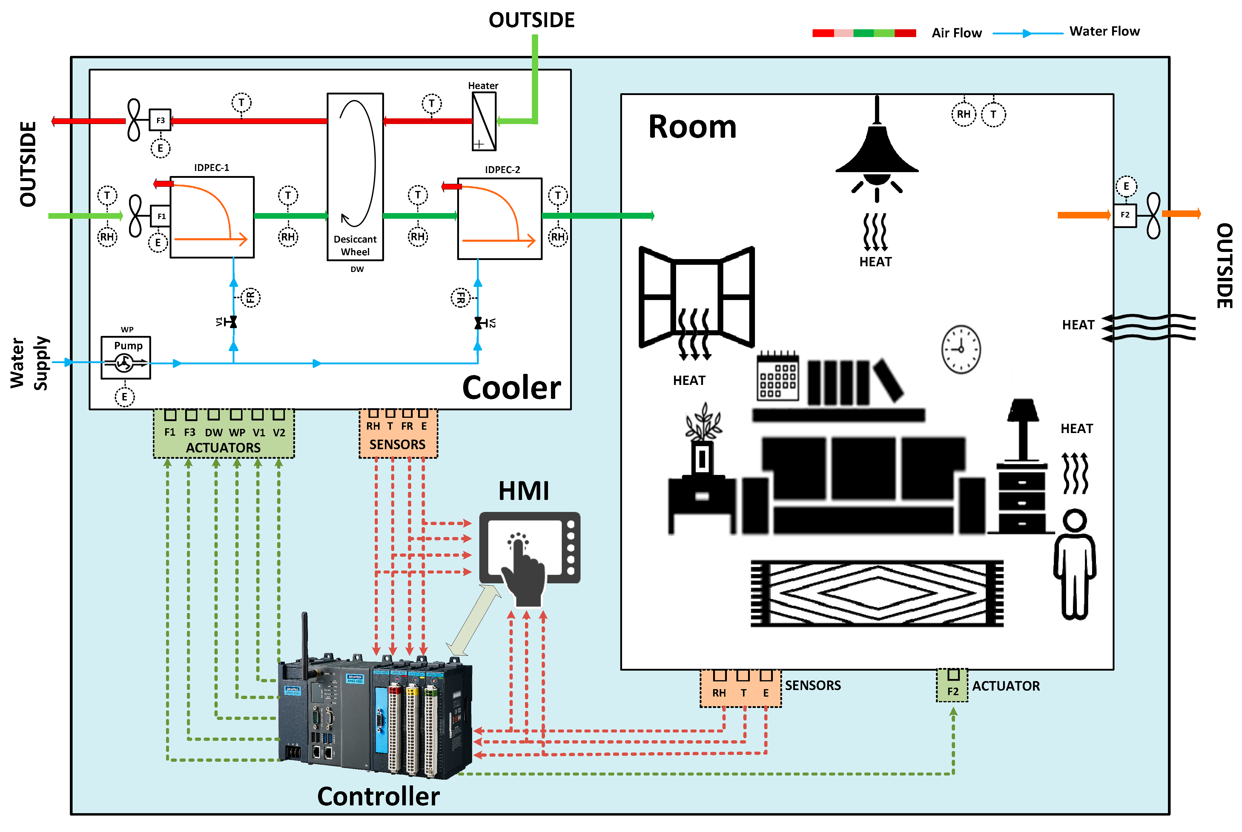
18], whose cooling performance was investigated under different conditions. The performances of these systems, which were selected to implement a control strategy due to their high performance, have been further increased by the additionally developed independent temperature and relative humidity control strategy. This air cooling system consists of two DPC systems, one for pre-cooling and the other for post-cooling, and a unit with a desiccant wheel and heater for extra dehumidification. The general scheme of the controlled process is given in detail in
Figure 1. The cooling system in the figure uses a cross-flow dew-point indirect evaporative cooler (DPIEC) as the pre-cooler and the counter-flow DPIEC as the post-cooler. The air taken from the atmosphere with the F1 fan is first cooled by entering the pre-cooler DPC (DPIEC-1). After this stage, if needed, this air is subjected to an extra dehumidification process via the desiccant wheel (DW). How much moisture will be removed from this air depends on the operation of the desiccant wheel cooling system. The air used in the desiccant wheel for the dehumidification process is taken from the atmosphere with the F3 fan, conditioned by the heater, and given back to the atmosphere. Meanwhile, moisture is removed from the actual air by the heat and mass transfer between the air passing through the desiccant wheel and the cooled air.
The rotation speed of the desiccant wheel has been accepted as the main effective parameter of the amount of moisture removed, and it is aimed to control the dehumidification with the control of the motor that rotates the desiccant wheel. Then, the dehumidified air enters the post-cooler DPC (DPIEC-2) where the second cooling process takes place, where it is further cooled and given to the room. The air in the room is discharged to the outside and thus the air circulation of the process is completed by the F2 fan. It is assumed that all fans (F1, F2, and F3) are assumed to be the same and work in the same operating modes for the continuity of air circulation in the whole cooling system. In addition, there is a water pump (WP) for supplying cooling water to the DPIECs. For this water pump, which provides a low and constant flow water supply during the normal cooling performance of the system, an extra “cleaning” mode has been added in order to periodically clean the channels of the heat exchangers in the DPCs.
As seen in the figure, there are sensors that measure the temperature (T), and relative humidity (RH) values of the room, the cooler, and the atmosphere. The data received from these sensors and the set values entered by the user are evaluated in the controller, and control inputs are generated for the actuators (F1, F2, F3, DW, WP) in the cooler. With these control inputs, the actuators are operated at different speeds throughout the process depending on the ambient conditions, and both the room comfort is provided faster and less energy is consumed. As can be seen in the figure, in addition to the temperature and relative humidity sensors, a flow rate sensor (FR) is used to measure the flow of the cooling water fed to the DPCs, and an energy meter (E) is used to measure the energy consumed by the actuators. In addition, a human–machine interface (HMI) was added to the system. With this HMI, the user can enter the set values for the room and monitor the data as a result of the measurements made by the sensors.
3. Model Development
The cooling system, whose geometry is given in
Figure 1, consists of two parts. The first of these is the pre- and post-cooled desiccant wheel part and the second is the room which is the cooled environment. For this reason, it is necessary to obtain both heat transfer (for temperature change) and mass transfer (for relative humidity change) models for both sections. Since the main purpose is to test the temperature and relative humidity control performance of the control strategy developed in the study, simple heat and mass transfer equations were used during the modeling, and a black box system modeling that produced the correct output for the given inputs was made. According to the results of the experimental study by Pandelidis et al. [
18], temperature and relative variation models were obtained for both the room and the cooler in these models.
In the model created for the temperature change of the atmospheric air taken into the cooler at the cooler outlet, firstly, a relation was established between the temperature of the air taken in the cooler and the speed of the fan. While extracting this relation, it is assumed that the initial temperature of the air taken into the cooler is equal to the atmospheric temperature.
where
,
,
and
denote the speed of the fans, the coefficient, which is used for conversion from rpm to temperature, the temperature of the intake air, and the temperature of the atmospheric air, respectively. After that, this temperature is used to calculate heat gained in the cooler due to this hotter intake air from the atmosphere. The gained heat is shown as:
where
denotes the thermal resistance of the cooler. Then, the variation of the temperature in the cooler is determined as:
where
,
,
,
and
represent the temperature of the air at the outlet of the cooler, the gained heat due to intake of atmospheric air, heat gained due to disturbing effects in the cooler such as convection and conduction from the cooler and other unknowns, the mass of air inside of the cooler and the heat capacity of the air, respectively. Finally, the relation between the fan speed and temperature variation of the air due to the cooling process is obtained. Thus, the temperature change process, which will be used in the control strategy for adjusting the cooling performance of the cooler by adjusting the fan speeds, is obtained.
The fan in the room operates at the same speed as the other fans in order to ensure successful air circulation. For this reason, heat transfer takes place between the air at the temperature
at the cooler outlet fed to the room and the existing air in the room. This heat transfer continues until an equilibrium is established in the room. In addition, there are disruptive effects in the room that try to disrupt this balance. Heat gain from windows, doors and roofs, and heat gains from people and machines in the environment constitute these disruptive effects. While the cooling air supplied to the room tries to cool the room, the room air is forced to warm up due to these disruptive effects. This significantly affects the comfort of the room. With the effect of the cooler air at the cooler outlet fed to the room, the heat loss in the room air is compensated by Equation (4):
where
,
and
denote the temperature of the room air, the equivalent thermal resistance of the room, and heat losses, respectively. The change in the temperature of the room air with the effect of heat loss due to the heat loss in the room caused by the cooling and the heat gains (
) due to the deteriorating effects is determined by using Equation (5).
Thus, the instantaneous room temperature, which is fed back into the control, is obtained. By adjusting the fan speeds of the air taken from the atmosphere, the temperature of the cooler outlet air is changed, and thus the temperature of the room is adjusted, and the whole system temperature change equations are obtained. An error input is created for the controller by comparing the instantaneous temperature of the room with the desired reference temperature. For this reason, the correlation between the fan speed and the change in room temperature is of great importance.
After the temperature change modeling was completed, a similar modeling process was performed for the mass transfer process. The change in the relative humidity of the air taken into the cooler is mostly realized during the desiccant-wheel-based cooling process. For this reason, in the control strategy developed, the dehumidification amount is adjusted by changing the speed of the desiccant wheel. There is a direct proportionality between these two parameters and the relationship between the change in the relative humidity of the air dehumidified in the cooler and the speed of the desiccant wheel and the change created by this less humid air fed into the room in the room air need to be modeled. For this purpose, the relation between the desiccant wheel’s speed and mass transfer is determined, firstly. The speed of the desiccant wheel is converted to vapor mass in the air as follows. The relative humidity of the intake air (
is assumed to equal the relative humidity of the atmospheric air (
):
where
,
and
indicate the speed of the desiccant wheel, the converting coefficient between the speed and vapor mass variation, and the vapor mass, respectively. Then, the variation of the relative humidity in the cooler is determined by using the variation of vapor mass due to DW’s speed change. The relative humidity of the air at the outlet of the cooler is:
represents the disturbing effects due to uncertainty and unknown mass transfer in the cooler. They lead to increase in the relative humidity of the air.
is the coefficient for converting vapor mass to relative humidity. Finally, the relation between the speed of the desiccant wheel and the variation in the relative humidity of the air is obtained for the cooler. After that, the air is supplied into the room and the variation of the relative humidity of the room’s air is determined as a function of supplied cooler air’s relative humidity. Similar to the temperature variation process, a balance will be tried to be established by mass transfer between the less humid air fed and the humid air in the room. For this purpose, firstly, the mass change caused by the relative humidity of the air at the cooler outlet was calculated:
where
represents the vapor mass. Then, the variation of the relative humidity of the room’s air (
is determined by using Equation (9) as a function of vapor gains due to disturbance effects (
and vapor loss due to the dehumidification process in the cooler.
Thus, the relationship between the rotational speed of the desiccant wheel and the variation of the relative humidity of the room is obtained. With the control strategy developed using this relationship, relative humidity control will be provided by changing the speed depending on the process conditions. The change in the relative humidity of the room will be monitored instantaneously according to certain speeds and the speed will be adjusted by the controller according to the error between the reference value and the reference value. Rotation speed values for fans and desiccant wheels are determined by evaluating both temperature and relative humidity error signals coming to the controller. To generate these rotational speeds, voltage is generated for each actuator at the controller output. These voltage values are transmitted to the motors of the actuators and rotation is provided with a speed value in return for the incoming voltage. It is assumed that the motors of all actuators are DC motors, and the relationship between the supply voltage and the rotational speed is obtained using the following equations:
where
,
and
denote the rotational speed of the motor, the supply voltage, and current, respectively. The values and descriptions of the other parameters are shown in
Table 1. These values of the parameters are constant during the process and these values are used during all simulations in the considered case.
4. Development of Control Strategy
A control strategy was designed to control the temperature and relative humidity of the room against disturbances, unknowns, and uncertainties. The purpose of this control is to bring the room temperature and relative humidity to the desired values quickly and to keep them constant at these values by using less energy. In order to control the temperature and humidity of the room, the temperature and humidity values of the air at the pre-cooled desiccant air cooler outlet must be adjusted. For this purpose, the speeds of the fans and desiccant wheel are adjusted by the developed control strategy for controlling temperature and relative humidity, respectively. Additionally, the water pump, which is used for supplying water into the DPCs, is controlled to switch between stop, normal operating mode, and flashing mode. Thus, the controller sends control inputs to these three actuators and arranges its operations in a way that provides maximum comfort with less energy according to system conditions and set values. The designed feedback control structure and basic scheme of the designed control strategy are shown in
Figure 2.
Figure 2a shows the general feedback control system structure and it consists of sensors, controllers, comparators, and processes (cooler and room). The room conditions are always measured by the temperature and relative humidity sensors during the process and the actual values of these quantities are fed back to the comparator unit to compare set (desired) values and to determine the actual error at the room conditions. These error values are sent to the controller for evaluation and control inputs are created for the actuators in the system according to the control strategy. These control inputs regulate the operating modes of the actuators to provide fast/robust room comfort and energy efficiency according to ambient conditions and system conditions. The developed control strategy is indicated in
Figure 2b, clearly. In the developed control strategy, there are four main units such as a mode selection unit, fans control unit, desiccant wheel control unit, and water pump control unit. The mode selection control unit decides the operation modes of the actuators depending on the system conditions such as the ON/OFF situation of the cooler, the conditions of the atmospheric air, the errors between the actual and set values, and the condition of the water pump. After that, the mode selection unit decides the operation mode of each actuator and sends the mode selection commands to each control unit. In these units, three different operating modes have been determined for each actuator. The first modes are the OFF mode for fans and the desiccant wheel, both actuators do not work in this mode. In the second mode for the fans and desiccant wheel, the actuators are at low speeds before starting to operate the cooler in active control mode and the atmospheric air is supplied to the room by providing cooling and dehumidification. In this mode, the operation takes a short time to ensure stable air circulation so that the first air supply takes place and the cooler goes into active mode. At this stage, the atmospheric air is hotter than the room temperature, and the room temperature and relative humidity increase during this short period. After a certain time, the cooler switches to the third mode for the fans and desiccant wheel for active control of the temperature and relative humidity by adjusting the speed of these actuators. In a cooling operation, if the measured temperature/humidity deviates from the desired temperature/humidity values, the controller changes the heat input/water mass output in proportion to the magnitude of the deviation. For the control technique, proportional (P) control is preferred due to its simplicity, suitability for real-time operation, and easy applicability to industrial operations. However, classical P control is improved by adding different operation modes and automatic Stop/Run properties. So, P control aims to reduce the error value obtained after comparing the desired point with the actual value by multiplying it with a coefficient (
). In this control technique, it is the choice of
value that is the most effective parameter on the control performance. The ideal
value varies from system to system in which the P control is used. P control is expressed by the following formula:
where
and U represent the error and the control input at the controller output, respectively. The
Kp values in the developed control strategy were determined by the trial and error method and operation conditions to achieve successful performance. During the adjustment of
Kp values for both temperature and relative humidity, attention was paid to ensure that the set value is the fastest and most suitable for heat/mass transfer physics without steady-state error and overshoot. For this reason, the time responses of the temperature and relative changes in the room were investigated for different
Kp values. The
Kp value is determined when the desired time domain analysis criteria, which are zero overshoot and steady-state error, and short settling time, are obtained. As a result of this process, this value was determined to be 7500 for the control of the fans, while it was determined to be 18 for the desiccant wheel, and these values are used for all simulations under the considered case. With the control inputs produced in this active mode and changing the actuator speeds according to the ambient conditions, room comfort is provided in a fast and energy-efficient way.
In addition, an automatic Stop/Run mode has been added to the developed control strategy to increase energy efficiency. In this mode, the room conditions are brought to the desired values and kept at these values for a certain period, then the cooler is switched to OFF mode (fans and desiccant wheel are stopped) until the room comfort deteriorates. Then, the cooler is switched back to ON mode and the room conditions can be quickly adjusted to the set values in the active control mode. The room comfort deterioration limits are determined as +2 °C variation in temperature and +2% variation in relative humidity. Thus, the actuators will operate intermittently depending on the magnitude of the disturbance effects, and energy savings will be achieved by stopping the actuators at certain intervals instead of constantly consuming energy. Like other actuators, a three-mode operation is designed for the water pump. The first mode is the OFF mode, which also stops the water pump when the cooler is off. There is a second mode to feed low-flow water into the channels of the water pump DPCs when the chiller is on. During the entire operation, the water pump operates in the second mode and pumps water at a low flow rate to the channels for cooling. The third mode of the water pump is the cleaning (flashing) mode which creates a high flow rate and intermittent water supply for channel cleaning. This cleaning mode is automatically activated after user instructions or after a certain period of time and ends automatically after cleaning for a certain period of time. In order to operate in this mode, the cooling part of the cooler must not work.
5. Results and Discussion
In this study, the control of the desiccant wheel and pre-cooled dew-point evaporation-cooling-system-based cooler is investigated for achieving high cooling performance with less energy consumption. The temperature and relative humidity of the room are controlled independently with a proportional-based new control strategy. With this new control strategy, the comfort of the room is adjusted quickly and robustly by managing the speed of the actuators in the cooler according to the operating conditions. By using variable speed actuators, the cooling performance of the cooler is improved and the energy efficiency increases with the adding extra operation modes to the control strategy. It was mentioned that the developed control strategy leads to a more energy efficient performance than the classical ON/OFF controller and classical proportional control with these adding modes such as automatic Stop/Run and different speed modes for each actuator. In this section, the control performance evaluations of the developed controller software were performed and the performance of reaching the set values and the energy-saving performance were analyzed.
In the considered case, the temperature and relative humidity of the atmospheric air are equal to 32 °C and 60%, respectively. However, the initial temperature and relative humidity are assumed to be lower than that of the atmosphere. They are equal to 28 °C and 50% and the heat and mass transfers from the outside to the inside lead to an increase in the temperature and relative humidity at the inside of the room and cooler. The temperature and relative humidity set values of the room were changed by the user during the operation. Set values were changed at 800 s for both room parameters. In the 800th second, the temperature set value was reduced from 24 °C to 21 °C and the relative humidity set value was reduced from 43% to 35%.
The control performances of the cooler and the produced control inputs for fans and DW are given in
Figure 3. As can be seen from the figure, the START instruction was given to the cooler, which was still closed, at 75 s. After that, the water pump starts its operation in the normal operating mode (Mode-2). Then, the fans and desiccant wheel started to operate in the low-speed mode (Mode-2) after the 150th second. Since the atmospheric air is fed into the room without being fully conditioned in this period, it causes an increase in the room temperature and relative humidity. After the 150th second, the cooler switches to active control mode, and the cooler air is conditioned in line with the determined set values. The first set value for the temperature, 24 °C, was reached in approximately 650 s. If there is no change in the set value after this value is reached, the process will continue until the ON/OFF mode is active.
It is seen from
Figure 3c that there is a similar situation for the relative humidity value and the first set value of 43% relative humidity is reached before the 500
th second. The state of reaching these set values continued until the change in the set values occurred at the 800
th second, and after the new set value was adjusted, the process of reaching new values for both temperature and relative humidity began. The new set values (21 °C and 35% RH) were reached at 1300 s for temperature and at 1100 s for relative humidity. The results show that the developed controller has a successful performance in bringing the room to comfort quickly and it has a robust performance against the disturbance effect. It is also seen that the control performance after changing the set values is good, too.
Then, after a certain time, the automatic Stop/Run mode is activated and the cooler is turned OFF for energy saving. After this moment, the temperature and relative humidity of the room increase depending on the disturbing effects. When the differences between instantaneous values and set values exceed the determined critical values, the cooler is operated in active control mode (Mode-3 for fans and desiccant wheel). The room temperature and relative humidity, which reach the set values again, remain at the set values until the automatic Stop/Run process, which will be repeated after a certain period. The control inputs for the fans and desiccant wheel are shown in
Figure 3b,d, respectively.
Figure 3b shows the control input signal generated by the controller for the fans. The fans regulate the flow rate of the air by changing their speed by working in line with the orders (voltage values) coming from the controller. There is an inverse relationship between the operating speed of the fans and the cooling performance of the cooler. The slowing down of the airflow passing through the cooler increases the amount of heat transfer from the dry channels to the wet channels. The air that loses more heat by passing more slowly will be fed into the room in a cooler way. For rapid cooling of the room air, the cooler outlet air also needs to be cooled as much as possible. For this reason, after the cooler is switched to active control mode, the operating speed of the fans should be reduced to obtain more cooling performance.
According to the results obtained, when the cooler switches to active control mode (Mode-3) the control input, which starts around 15 V, drops to 8 V until it reaches the first set value. Thus, the fan speed is reduced to reach the first set value, and the necessary cooling is provided by slowing the airflow. With the set value change occurring at the 800
th second, cooler air is needed at the cooler outlet. For this reason, it is necessary to reduce the fan speed further after this moment. As can be seen from the figure, the control input signal determined for the fans decreased to 7 V. Thus, the fan speed is further reduced compared to the first case, and the rate of heat transfer within the cooler has increased. With this control input value, the room temperature reached the second set value of 21 °C. The cooler was stopped after the automatic Stop/Run mode was activated at 1650 s. For this reason, 0 V was sent to the fans to stop the fans during this period. Later, after the cooler was turned ON again, the fans started to work with a 7 V supply again. The variations in the speed of the fans are shown in
Figure 4a, in detail. In accordance with the physical condition described above, it can be seen that the fan’s rotation speed was 1200 rad/sec for the first set point, while it was reduced to 1000 rad/sec to reach the second set point.
The control input of the desiccant wheel is obtained as in
Figure 3d. The operation modes of the desiccant wheel are shown in
Figure 4b and these modes are similar for the fans. In order to reach the initial set value of the room, 43%, the dehumidification in the cooler must be increased. The dehumidification in the cooler and the speed of the desiccant wheel work in direct proportion. This means creating a higher mass (vapor) transfer rate to increase dehumidification. A higher mass transfer rate is made possible by moving the wheel faster. Considering that the desiccant wheel’s speed is directly proportional to the supply voltage, the desiccant wheel’s supply input was increased to 18 V by the controller in the time it took to reach the first set value. Since the second set value is lower than the first set value, the air at the cooler outlet needs to be further dehumidified. For this reason, it is necessary to increase the speed of the DW. To increase the speed of the DW, the DW’s control input voltage was increased by the controller after the 800
th second and was reduced to approximately 22.5 V. Thus, it was ensured that the room relative humidity reached the second set value in a short time. Similar to the fans, 0 V is sent in the DW during the automatic OFF process to stop it. Then, when the cooler was ON again, the DW was started to provide the deteriorated relative humidity balance in the room, and the dehumidification process was started. The rotational speed of the DW is shown in
Figure 4c. It is shown that the rotational speed of the desiccant wheel was determined at 4400 rad/sec to reach the first set point and 5300 rad/sec to reach the second set point.
After that, the powers and the energies consumed by the actuators depending on the actuator voltage values determined by the control strategy according to the ambient and process conditions were analyzed. The speed of the fans and the power consumed by the fans during operation vary depending on the control input voltage determined by the controller.
Figure 5 shows the variation of fan power and energy consumption of a fan as a function of time, respectively. It can be seen that the power consumed by the fan varies similarly with the supply voltage.
Figure 5b shows the variation of the energy consumed by a fan during the operation concerning time. As can be seen from the figure, the energy consumption of the fan increases from the time the fans start to work until the automatic stop occurs. With the decrease of the set value in the 800
th second, the power consumed decreases due to the slowing down of the fans. Depending on the decrease in power, the energy consumed by the fan decreases at a certain time. As seen in the graph, the slope of the increase in energy changes after the 800
th second. The total energy consumed during the active control mode of the cooler is observed as 39 KJ. Between the 1650
th seconds and the 2100
th seconds when the cooler is OFF, the consumption remains constant at 39 KJ. Afterward, the energy consumption continues to increase as the fans restart and the energy consumption reaches 45 KJ for a fan at the end of 2500
th seconds. Approximately 60% less energy is consumed compared to conventional ON/OFF control, in which the fans are supplied with maximum voltage (20 V) while the cooler is running. In addition, 19.65% energy savings were achieved by consuming 45 KJ instead of 56 KJ with the automatic Stop/Run feature added to the control strategy.
The operation of the desiccant wheel is as important as the fans in the calculation of the total energy consumed by the cooler during the cooling process. Similar to the fans, consumed power and energy analyses were made for the desiccant wheel.
Figure 6a shows the variation of the desiccant wheel’s power as a function of time for this case. It has similar behavior to the control input and rotational speed.
Figure 6b shows the variation of the energy consumed by the desiccant wheel during the operation concerning time. As seen in the figure, the energy consumption increases from the time the desiccant wheel starts to work until the automatic stop occurs. With the decrease of the set value in the 800th second, the power consumed increases depending on the acceleration of the desiccant wheel. Depending on the increase in power, the energy consumed by the desiccant wheel increases at a certain time. For this reason, the slope of the increase in energy increases after the 800th second. During the active control mode of the cooler, the total energy consumed by the desiccant wheel is observed to be approximately 820 KJ. Between the 1650th second and the 2100th second when the cooler is OFF, the consumption remains constant at 820 KJ. Afterward, the energy consumption continues to increase with the desiccant wheel restarting. At the end of the 2500th second, the total energy consumption of the desiccant wheel reaches approximately 1100 KJ. If there was no automatic Stop/Run mode, 1400 KJ of energy would be consumed during the operation of the desiccant wheel, and 21.43% energy savings were achieved with this feature. Compared to the classical ON/OFF control (the desiccant wheel consumes 1754.38 KJ in this control mode), 37.3% energy savings were achieved during the 2350 s of operation of the desiccant wheel with the developed control strategy.
In addition to the fan and desiccant wheel, the other equipment that consumes energy in the cooler is the water pump. The working state of the water pump is discussed in the next case. As mentioned before, the water pump has three operating modes. When the cooler is ON, Mode-2 is used to feed water to the channels at a constant and lower flow rate. When the cooler is OFF, Mode-3, which is used as flashing mode, is used to clean the channels. In this mode, the high flow rate of water is fed to the channels at certain intervals, and cleaning is provided. The operating performance and energy analysis of the water pump, which consumes energy during operation in Mode-2 and Mode-3.
Figure 7 shows the change in room temperature for the process that is manually turned off and the flashing mode turned on, and the change in the operating modes of the water pump during the process. The water pump (Mode-2) that starts running at 75 s starts to consume energy. As seen in the figure, it continues to operate in Mode-2 from this moment until the 2650th second when the cooler is switched to manual OFF mode. In addition, the water pump continues to run automatically in the 1650th second when the OFF mode is operating. In the figure on the upper part of
Figure 8, the increase in room temperature with disruptive effects can be seen as a result of the manual shutdown at the 2650th second. As can be seen, the disturbing input effect to which the system is exposed is quite high. Despite these high amplitude disturbance effects, it is concluded that the cooler is a successful controller for the control of temperature and relative humidity in active control mode. After the cooler was closed manually, the flashing mode (Mode-3) of the water pump was activated manually at the 3550th second. At this stage, high flow rate water is fed to the channels periodically. At 5200th second, the flashing mode was turned off manually and the water pump was stopped (Mode-1).
The control input applied to the water pump by the controller and the energy consumption of the water pump are shown in
Figure 8. As can be seen in
Figure 8a, the operating voltage for the water pump is determined as 1 V during operation in Mode-2. With this voltage supply, the water is sent to the channels at a low flow rate. With the manual shutdown of DPEC at 2650th second, 0 V is sent to the water pump by the controller, and the operation is stopped. Next, the flashing mode is activated at the 3550th second and the water pump pumps high flow rate water into the channels for 40 s every 100 s. After the cleaning process is finished, the flashing mode is turned off manually and the water pump is stopped. The cleaning mode of the water pump can only be activated when DPEC is OFF. The variation of the energy consumed by the water pump with respect to time is given in
Figure 8b. As can be seen from the figure, in Mode-2, which is a low-speed operating mode, the energy consumption increases with a low slope during operation. The total consumption of the water pump until 2650th seconds is 3.5 KJ. Since the water pump does not work until the flashing mode is activated, no energy is wasted. In flashing mode, energy consumption increases rapidly as higher flow rate water is pumped in the direction of control input with 5V amplitude. After flashing mode, the energy consumption of the water pump reaches 56 KJ at the end of 6000th seconds.
If the energy consumption during 2500 seconds of desiccant cooling system (three fans + desiccant wheel + water pump) operation is evaluated, the total energy consumed by the cooler with the developed control strategy is 1238.29 KJ (135 KJ for the fans, 1100 KJ for DW and 3.29 KJ for WP). If the classical ON/OFF control was applied in the control of DPEC, the total energy consumed during the operation would be 2095.17 KJ. Thus, with the developed control strategy, 40.90% energy savings were achieved compared to the classical ON/OFF control. On the other hand, if the automatic Stop/Run feature was not added to the control strategy, it was determined that 1571.29 KJ energy would be consumed during the operation. It was observed that 21.19% energy saving is increased with this feature, which automatically turns the DPEC on and off without disturbing the room comfort.


 ,
, 


