Article

High-Velocity Metal Fragment: Motion Characteristic and Optimization Design

1
School of Mechatronic Engineering, Xi’an Technological University, Xi’an 710021, China
2
Norinco Group Testing and Research Institute, Huayin 714200, China
3
School of Energy and Power Engineering, Nanjing University of Science and Technology, Nanjing 210094, China
*
Author to whom correspondence should be addressed.
Appl. Sci. 2022, 12(19), 9922; https://doi.org/10.3390/app12199922
Submission received: 11 September 2022 / Revised: 26 September 2022 / Accepted: 29 September 2022 / Published: 2 October 2022

Abstract

:
This present work suggests a charge technique to produce a super high-velocity fragment (≥2350 m/s) using a 30 mm launching system. The steel cylindrical fragments with Brinell hardness HB ≤ 270 are designed according to STANAG 4496 in the experiment, and a test system including interval speed measuring device, pressure measurement and high-speed camera is employed to obtain the information on the velocity, pressure and muzzle field of the fragment. The flame characteristics presents an increasing area, and the fragment escapes the control of the muzzle field when the high-velocity fragment is flying out of the muzzle. Moreover, the projectile sabot can timely be separated from the fragment in the range of the first interval velocity measuring device. Based on this, the mathematic models on the interior ballistic process of the fragment movement are established to analyze the effects of various charge structures on the motion characteristic of the fragment. Comparisons of fragment velocity and chamber pressure of computational results are performed with experimental studies. A reasonable match has been obtained in these comparisons. Further, a discussion on the choice of charge parameters is performed by the optimization design for this super high-velocity fragment.

1. Introduction

The kinetic energy of the fragment is the main source in realizing the target damage, thus this damage ability strongly depends on the velocity and velocity attenuation rate of the fragment. However, the actual moving process of aerodynamic fragmentation is not well understood, but earlier theoretical and experimental efforts provide useful insight regarding the factors which probably are involved.
Some basic studies have emerged within the past 40 years to predict the phenomena of this fragmentation brought about by high-velocity impact or explosive events [1,2,3,4,5,6,7]. The prediction of mean fragment size through energy and momentum balance principles were mainly focused on. For example, Grady et al. [8] proposed a quantitative approach to govern the surface or interface area created in the fragmentation process by an equilibrium balance of the surface or interface energy and a local inertial or kinetic energy. This approach was also compared with experimental results of brittle fracture and shear localization in shock-loaded samples. Kipp et al. [9] adopted Mott analyses to explicitly account for energy dissipation during the fracture process and obtained these expressions of the nominal fragment size, fracture time, and dynamic fracture strain. Numerical analysis was also used to examine the interaction of ductile fractures and the conditions that might lead to arrest or completion of growing fractures. Then, their team [10,11] reported both numerical and experimental capabilities for characterizing the debris spray produced in penetration events and performed a series of high-velocity experiments specifically designed to examine the fragmentation of the projectile (6.35 mm diameter) during impact by using a two-stage light-gas gun. Glenn et al. [12] modified Grady’s model of the dynamic fragmentation process, in which the average fragment size was determined by balancing the local kinetic energy and the surface energy and revised model predicted that the strain energy should dominate for brittle materials, with low fracture toughness and high fracture-initiation stress. To solve the fragment size distributions, Englmant et al. [13] idealized the fracture of solids as the formation of fragments by randomly distributed cracks on a network and compared a two-dimensional material fraction of fragments whose size exceeds a sizes with the Mott distribution function. Grady et al. [14] provided an explanation for the behavior of debris ejected from the back surface of a target impacted by a high velocity projectile and obtained experimental results from high velocity impact tests of lead and uranium projectiles on lead and uranium martials. Sil’Vestrov [15] analyzed distribution characteristics of fragments arising during fragmentation of a steel projectile upon its normal impact on a thin bumper with a velocity of 2.5–7.3 km/s and obtained the character of fragmentation of the steel sphere changes from irregular fragmentation near the projectile-failure threshold to more uniform fragmentation with the maximum impact velocity with an increase in the impact pressure from 30 to 160 GPa. Cagle et al. [16] carried out simulations on a plastic projectile and both plastic and elastic targets to study the limiting cases in material properties that represented fragmentation behavior as a function of the target material. Myagkov [17] calculated the fragmentation behavior of aluminum projectile upon high-velocity impact on a thin aluminum shield by using the deformed solid mechanics on the base of a method of smoothed particle hydrodynamics and obtained that the critical impact velocity was a power function of projectile diameter and ultimate strength. Teng et al. [18] designed an explosively formed projectile to test an equivalent fragment impact on an equivalent tactical ballistic missile warhead by employing a flash X-ray facility to measure the profile and the velocity of the explosively formed projectile slug, which can provide a foundation for the resistance of military fortifications and nuclear power plant containment structures to penetration. Rabczuk et al. [19] proposed a SPH/MLSPH-method for high velocity concrete fragmentation, and they also compared the calculation results with the experiments. Johnson et al. [20] extended the experimental results from their previous report [21] to advance blasting in the field of mining engineering by consideration of the fragment size distribution and describes the characterization of two granite bar tests using X-ray computed tomography to establish fragment size distribution as well as particle shape characteristics. Myagkov et al. [22] analyzed the fragmentation behavior during high-velocity impact for the projectile-bumper system numerically and adopted a two-dimensional particle-based simulation to describe the interparticle interaction by the pair Lennard-Jones potential. Zelepugin et al. [23] studied the processes of deformation and destruction of finite-thickness targets during the high-velocity impingement of a group of compact impactors by establishing three-dimensional mathematic model on the base of the finite-element method and obtained a simple criteria for estimating the mutual influence between the impactors and the target.
In fact, many brittle materials encounter high-velocity impact, explosive loading, high-energy radiation and impingement of a shock wave, resulting in a fragmentation into numerous pieces. However, the rapid energy input is a significant issue regarding whether the fragment from the impacted body still has enough kinetic energy to maintain the damage ability for the target materials or objects. Based on balance principals of energy and momentum, some models which provide a foundation for analyzing the energy and momentum characteristics in a fragmentation event [24,25,26,27,28]. Persson [29] suggested a method to calculate the fragment ejection velocity, in which the ejection velocity was related to the strain energy and the fracture energy without considering the damage development of the material. Espinosa et al. [30] and Camancho et al. [31] developed Lagrangian finite element method of fracture and fragmentation by using cohesive-law fracture model and also carried out the comparison of the analyses results with the experimental results on the base of the effects of fragments size and friction between fragments. Miller et al. [32] conducted numerical simulations on the base of energy balance, and then compared their predictions of fragment size by using two mathematic models. Denoual et al. [33] presented various fragmentation regimes with respect to stress rate and volume by numerical simulations. Zhang et al. [34] established a dynamic fragmentation model on the base of the strain energy coupled with damage to quantifiably predict the fragment size and fragment ejection velocity and obtained the explicit expressions about the relation between the fragment size and the strain rate and that between the ejection velocity and the strain rate. Yen et al. [35] developed the composite-material model within LS-DYNA via a user-defined material subroutine that has been used to analyze the damage and ballistic behavior of composite laminates subjected to a series of ballistic impact conditions. Zhikharev et al. [36] carried out numerical simulations of fragment penetration of glass fabric/epoxy-phenolic laminates when the laminates with different thickness (1.95 and 3.90 mm) were subjected to ballistic impact of 6.35 mm diameter steel as a fragment simulator at different velocities, and the calculation results also had a good correlation with the experimental data in terms of ballistic curves. Judge et al. [37] established full 3D finite element models of multi-layer spiral-strand cables for fragment impact analysis and obtained both the localized and global response of the cables when subjected to fragment impact. Wang et al. [38] simulated the intersection of the aircraft and the fragment field under dynamic conditions and they also verified the feasibility of methods for the vulnerable structure distribution of the aircraft on the base of the shooting-line method and the Monte Carlo method. Grisaro et al. [39] has shown the results on perforated witness plates by enhanced intense-strip model and the numerical simulation was useful for a realistic evaluation of the structural response of a protective wall, which is subjected to the combined loading of blast and fragments. Kljuno et al. [40] proposed a developed physical model to estimate the projected surface area of the fragment for the fragments with different shape, mass, and velocity. Consequently, most previous studies mainly focus on damage degree of the target object and the fragmentation behavior of the fragment.
There are, nonetheless, many issues within the development of the steel fragment which impacts into the steel plate, such as how to improve the kinetic energy of the fragment via the launching system. In this paper, the launching system driven by the powder combustion-gas is firstly designed to propel the fragment projectile and then an experiment on the fragment is carried out to analyze the behavior of velocity attenuation and pressure curve in the movement process. In the last section, the mathematic models on the interior ballistic process of the fragment movement are also established to further analyze the effects of various charge parameters on the movement characteristics of the fragment. Furthermore, a charge technique is proposed to produce a super high-velocity fragment (≥2350 m/s) using this 30 mm launching system.

2. Experimental System

2.1. Experimental Device and Process

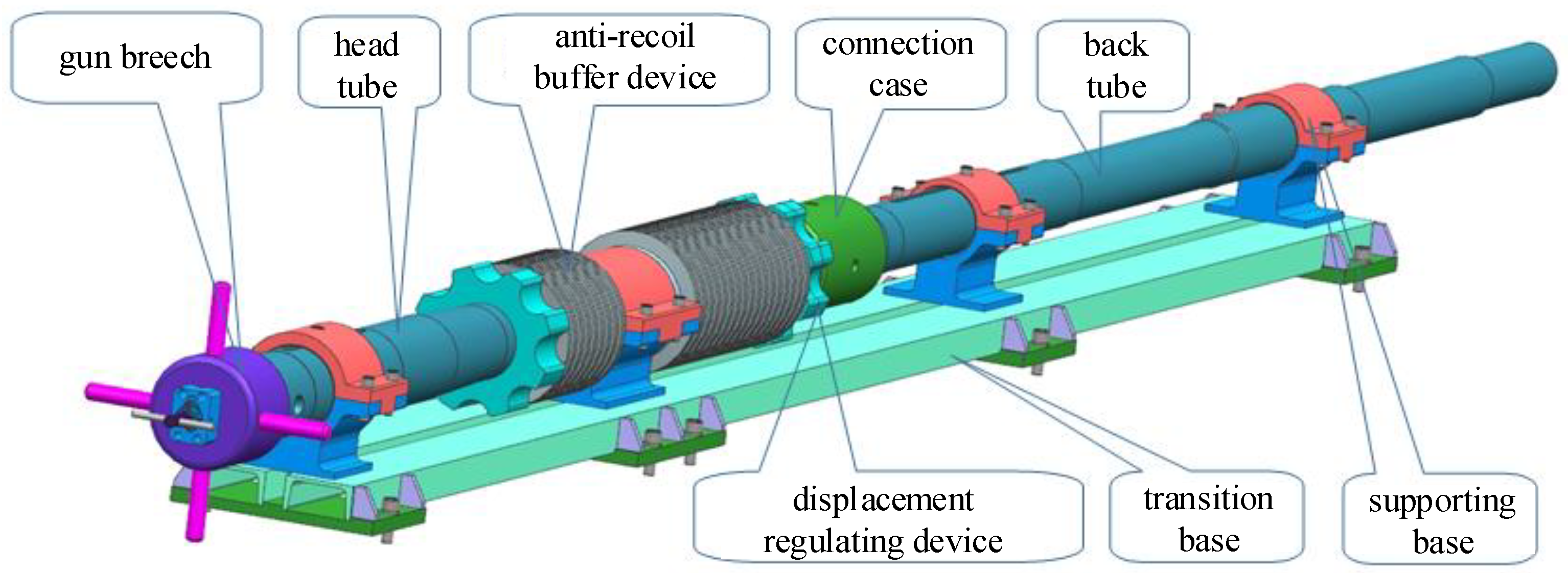
Experiments are carried out to analyze the movement characteristics of the fragment in the movement process, as shown in Figure 1. A 30 mm smoothbore gun drove by tubular powder with seven holes is designed to produce the fragment with high velocity in this experimental system. Figure 2 shows the detailed structure of the launching system, including gun breech, head tube, anti-recoil buffer device, displacement regulating device, transition base, connection case, back tube, and supporting base. The anti-recoil buffer device can absorb the recoil in the launching process. In this study, the buffer device is double buffer with recoil and advance and is installed on the back tube via adopting the apposition method of disc springs. The advance buffer is used to realize the brake and counter-recoil effect of the launching system, and the recoil buffer is mainly used to advance action when the counter-recoil is in place. This buffer device can satisfy the operating requirement of the maximum recoil of 183 KN that is enough for this experimental study. The combustion chamber in the head tube of the launching system is 35 mm caliber, and the length of the whole tube is 4.5 m.
The launching tube made of gun-steel is always working under the effect of the high-pressure combustion-gas, and thus the strength of the tube is designed according to the linear deformation potential theory. The tangential stresses of the inner surface and outer surface of the tube are calculated as the following equations, respectively:
σ i = 2 3 P 2 R e 2 + R i 2 R e 2 R i 2
σ e = P 2 R i 2 R e 2 R i 2
where, Ri and Re are the inner radius and outer radius of the tube, respectively. P is the pressure of the corresponding position of the tube where the projectile is located, and the unit is MPa. σi and σe are the tangential stresses of the inner surface and outer surface of the tube. The safety factors of the inner and outer stresses ni and ne are calculated as the following equations:
n i = [ σ ] σ i , n e = [ σ ] σ e
where, the permissible stress of the tube is [σ] = 1040 MPa and the maximum pressure of the tube is calculated as Pm = 400 MPa and then the corresponding results are shown in Table 1.
It can be seen in Table 1 that the safety factors of the inner and outer surface of the tube are all larger than 1.49 for the whole positions when the projectile is moving in the tube of the launching system. Consequently, the strength of the tube designed in the study satisfies the strength requirement.
In addition, the dedicated experimental projectiles are also designed according to the STANAG 4496, as shown in Figure 3. The projectile is composed of projectile sabot and fragment, and the fragment is surrounded by the projectile sabot to guarantee that the fragment cannot turn over in the tube. Meanwhile, the launching security in the tube and the flying stability in the air can be reached. The main function of the projectile sabot is to trap combustion-gases and transmit the thrust for the movement of the fragment. The projectile sabot is also preprocessed into four sections for the separation of the projectile sabot and fragment timely when the projectile is flying away from the muzzle of the launching system. In the experiment, the separation of the projectile sabot and fragment can be realized via adjusting the mass and shape of the fragment. The diameter of the fragment is 14.3 ± 0.05 mm, and the length-diameter ratio is 1. The Brinell Hardness is HB ≤ 270 with steel cylindrical body and the angle of the projectile is 160 ± 0.5°. Thus, the whole length of the experimental projectile is 15.56 ± 0.05 mm. The density of the projectile is 7.85 g/cm3 and the whole mass is 18.6 g.
In the experimental test system, the interval velocity measuring device is adopted to test the velocity and velocity attenuation of fragments in the movement process. The velocity measurement system is shown in Figure 1, and is mainly composed of fragmentation shields, and eight interval velocity measuring devices (namely IVMD). The velocity and velocity attenuation of the fragment can be calculated by the distance between two targets and the time difference when the fragment passes through zone-block device of the IVMD. The pressure test system is employed to obtain the pressure curve of combustion chamber when the gun powder is burning and propelling the projectile. In addition, the high-speed video camera system is also set near the gun muzzle to obtain a series of the flame evolution process.
In the experimental process, the gun primer located on the gun breech is firstly fired by the mechanical device, and then the high-temperature and high-pressure combustion-gas is produced with injection into the combustion chamber. Thus, the gun powder in the combustion chamber is ignited, rapidly producing amounts of combustion-gas. When the pressure of the combustion chamber reaches the launching condition of the projectile, the projectile can move along the back tube of the launching system. When the projectile leaves the muzzle of the launching system, the projectile sabot and the fragment realize an effective separation. Then, the fragment hits the target with a high velocity. The fragment can reach a desired velocity to damage the target via adjusting the grain configurations and powder charge. This is because the release rate of the combustion-gas for different shape of the powder is different, providing different energy for the projectile when the projectile with the same structure and mass is moving in the gun tube with an increasing velocity. Thus, the muzzle velocity of the projectile is different under different grain configurations and charge of the gun powder. The fragment can hit the target with a higher velocity when the muzzle velocity of the projectile is higher and the target position is the same.

2.2. Experimental Results and Discussions

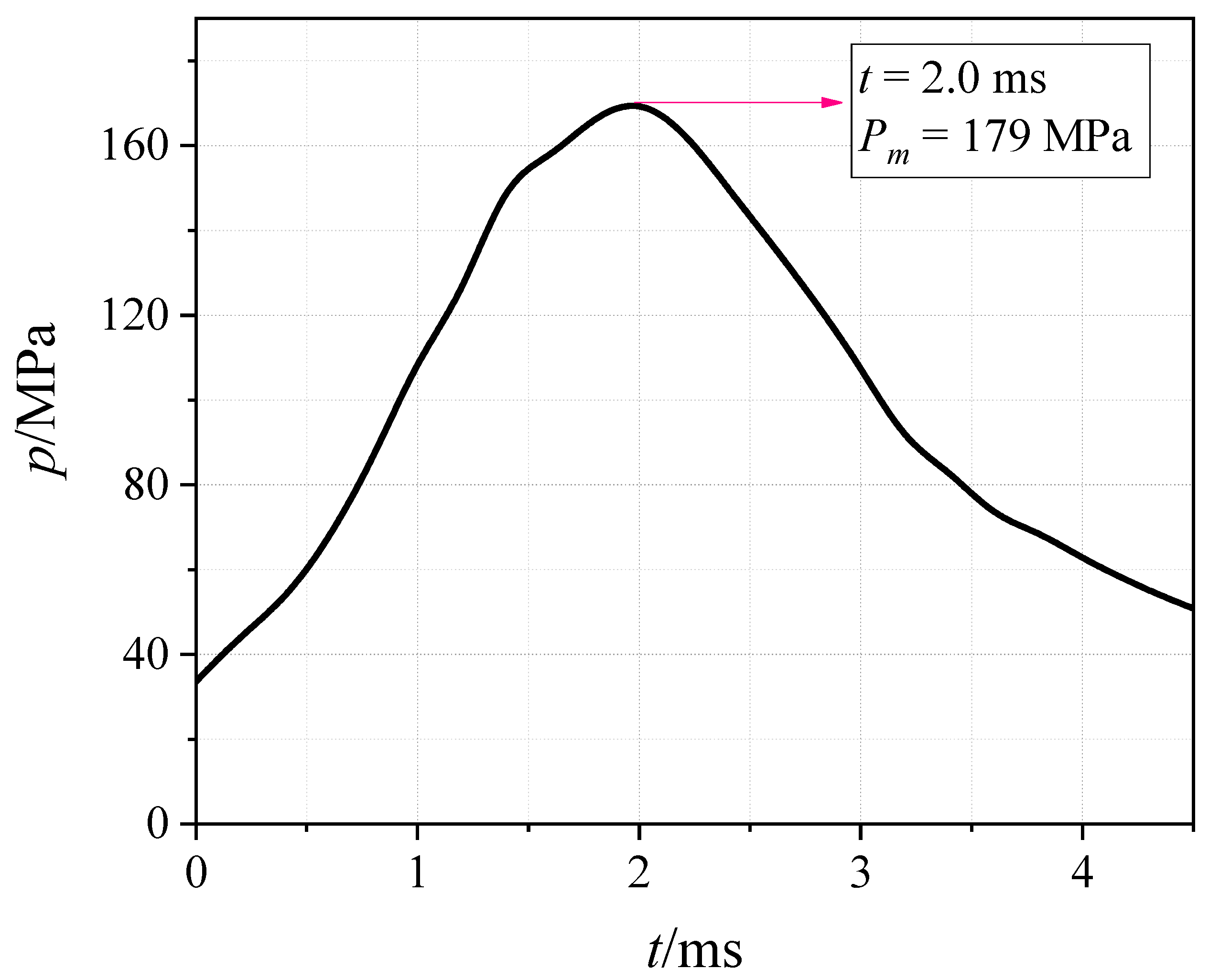
In the experiment process, the grain configuration is 5/7 tubular and the powder charge is 260 g. Figure 4 shows the pressure curve of the combustion chamber. When the pressure reaches 30 MPa, the projectile begins to move in the tube of the launching system. With the burning of the powder, the pressure of the combustion chamber is increasing. At t = 2 ms, the pressure reaches the maximum and the value is 179.3 MPa. The combustion-gas release rate increases with an increase in the pressure, providing more kinetic energy for the projectile, so the projectile velocity increases. The volume of combustion chamber gradually enlarges with the movement of the projectile. Consequently, the effect of the volume increment of the combustion chamber is larger than the release rate of the combustion-gas, and the pressure of the combustion chamber begins to decrease after 2 ms. Finally, when the projectile leaves the muzzle of the launching system, the pressure of the combustion chamber is only 45.6 MPa.
In the experiment, eight IVMDs are used to obtain the flight velocity of the fragment in the air. The distance between the first IVMD and muzzle of the launching system is 4.54 m. The distance between the first and fourth IVMDs is 6.242 m. The distance between the second and third IVMDs is 5.8 m. The distance between the fourth and fifth IVMDs is 6.8 m. The distance between the fifth and eighth IVMDs is 5.199 m. The distance between the sixth and seventh IVMDs is 4.755 m. The experimental results show that the fragment flies through these eight IVMDs at 2.616 ms, 2.737 ms, 5.987 ms, 6.114 ms, 10.172 ms, 10.309 ms, 13.323 ms and 13.467 ms. The distance between group IVMDs and corresponding interval times are shown in Table 2. Consequently, it can be seen the fragment velocity in the range of the second and third IVMDs is 1784.6 m/s and in the range of first and fourth IVMDs is 1784.4 m/s. With the movement of the fragment, the fragment velocity in the range of fourth and fifth IVMDs is 1675.7 m/s. Then, the fragment velocity decreases to 1577.6 m/s in the range of sixth and seventh IVMDs, which is the same with that in the range of fifth and eighth IVMDs. That means the fragment velocity is decreasing under the resistance effect. If the muzzle velocity of the fragment is lower, the kinetic energy of the fragment is not enough to damage the target. Thus, according to standard, the muzzle velocity of the fragment should be larger than 2000 m/s under the strength condition of the tube of the designed launching system.
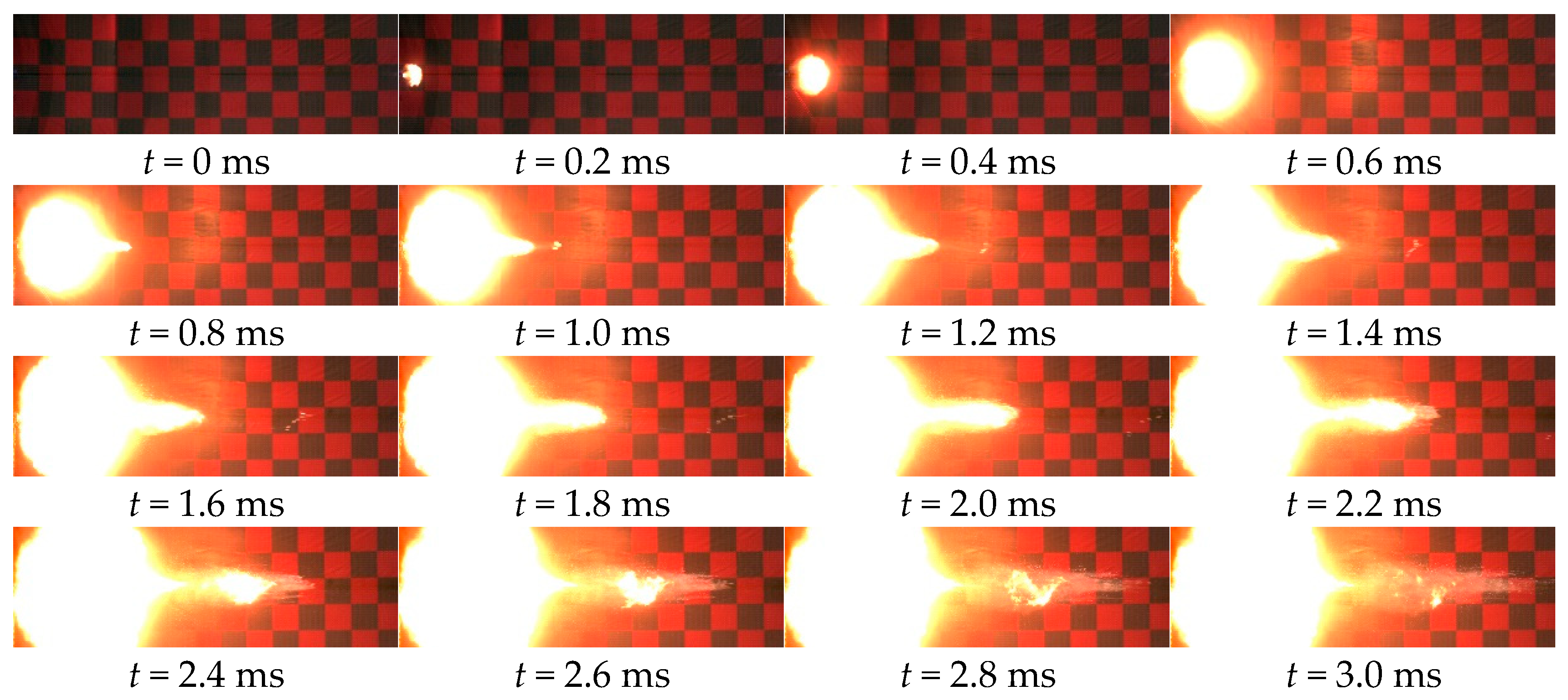
Figure 5 shows the flame evolution characteristics on the muzzle of the launching system. It can be seen that at the initial time, a small flame zone is formed with a mushroom-shape at 0.2 ms and the projectile is surrounded by the flame in 0.8 ms. This is because the combustion-gases with high-pressure and high-temperature formed by the burning of the gun powder are injected from the muzzle of the launching system when the projectile leaves the muzzle, forming a flame zone on the muzzle. With time proceeding, the flame zone increases and the shape also changes with a pointed cone, which indicates that the fragment begins to pass through the muzzle flame zone. At 1.0 ms, it is obvious that the fragment is far away from the muzzle flame zone and the muzzle flow has a little effect on the fragment velocity from 1.2 ms. When the projectile leaves the muzzle of the launching system, the pressure of the combustion chamber rapidly decreases and the burning rate of the gun powder is also decreasing. Consequently, the gun powder cannot burn out due to the lower burning rate. It is obvious that the residual gun powder is injected from the muzzle and forms many particles near the muzzle at 2.4 ms.
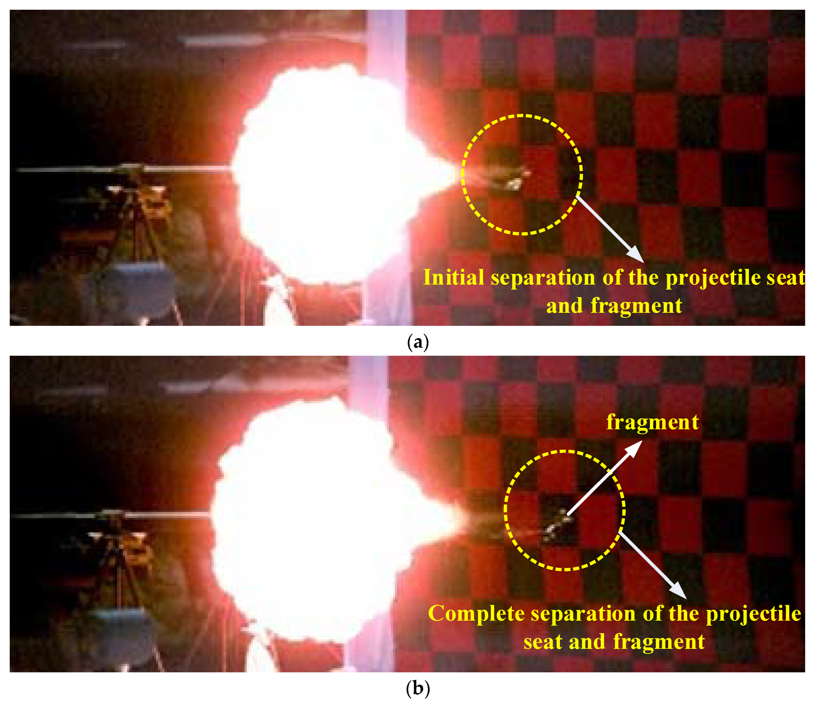
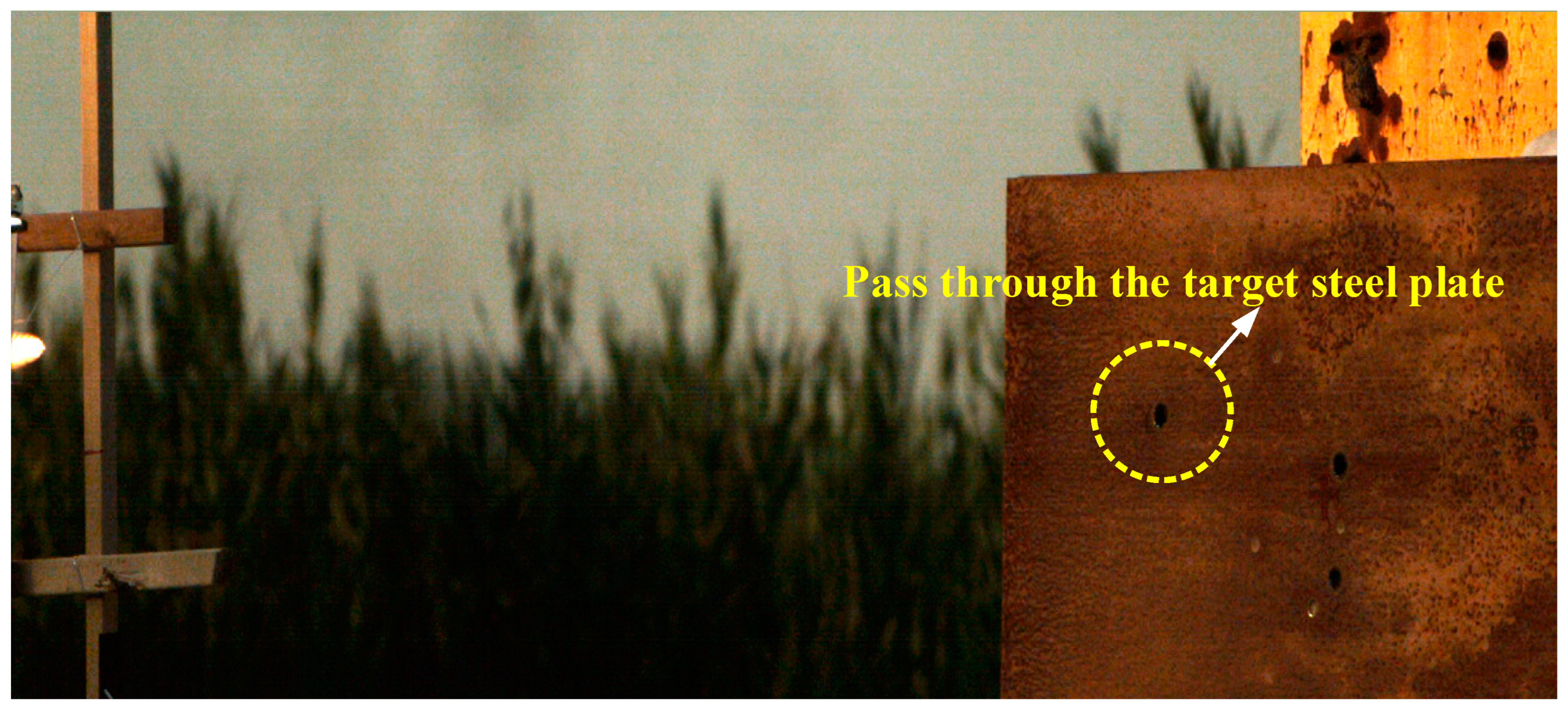
To further analyze the separation behavior of the projectile sabot and fragment, Figure 6 shows the movement process of the projectile at 1.2 ms and 1.4 ms, which is obtained by tracking the projectile via the high-speed camera system. It can be seen that at 1.2 ms, the fragment begins to be separated from the projectile sabot. Since the projectile sabot is preprocessed into four sections, these four sections are not all separated with the fragment. It is also obvious that the projectile is not far away from the muzzle of the launching system and has not reached the first IVMD. That is the projectile sabot and fragment can be separated timely once the projectile leaves the muzzle of the launching system, which satisfy the requirement of the fragment projectile. At 1.4 ms, the projectile sabot is completely separated with the fragment. The fragment can still fly in the air with a larger velocity and the sections of the projectile sabot are being left behind due to light weight and small inertia resistance. Figure 7 shows the deformation shape of the target steel plate after the fragment passes through the target. The thickness of the steel plate is 20 mm. It can be seen that the kinetic energy of the fragment is enough to damage this target. However, when the thickness of the steel plate increases, it is difficult to totally pass through the steel plate under this experimental condition. So, we can improve the parameters of the powder in the combustion chamber, providing more energy for the fragment under the restrain effect of the loading density and tube strength.

3. Optimization Calculation

According to the design requirement, the muzzle velocity of the fragment must be larger than 2000 m/s and the maximum pressure of the combustion chamber is less than 400 MPa when the projectile leaves the muzzle of the launching system. Based on this, the tube can perform the loading capacity to the maximum. Since the experiment numbers are limited, it is difficult to obtain the optimal muzzle velocity of the fragment. Here, the numerical simulations are also carried out by using the interior ballistics model under the conditions of different grain configurations and powder charge.

3.1. Calculation Method

The accelerating movement process of the projectile in the tube of the launching system is calculated by classic interior ballistics model and the powder in the combustion chamber is assumed as the geometric burning law. When the projectile reaches the starting pressure, the accelerating process of the projectile in the tube occurs. According to this description, the interior ballistics model in the launching process is presented as follows:
Form function of the powder:
ψ = { χ Z ( 1 + λ Z + μ Z 2 ) , 0 Z 1 χ s Z ( 1 + λ s Z ) , 1 < Z < Z k 1 , Z = Z k
where ψ is the burning percentage of the powder, Z is the burning relative thickness, χ , λ , and μ are the form characteristic quantities. χ s and λ s are the form characteristic quantities when the burn surface of the powder decreases. Zk is the burning relative thickness when the powder burns out.
Burning law of the powder:
d Z d t = u 1 p n e 1
where p is the pressure of the combustion chamber, u1 is the burning coefficient of the powder, n is the burning exponent, e1 is half of the web-thickness of the powder, and t is the interior ballistic time.
Energy equation:
S p ( l ψ + l ) θ = f ω ψ θ φ 2 m v 2 l ψ = l 0 [ 1 Δ ρ p ( α 1 ρ p ) Δ ψ ]
where l0 is diameter shrunk length of the diameter, Δ is the charge density, f is the impetus of the powder, ρ p is the powder density, k is adiabatic index and θ = k 1. Moreover, ω is the powder weight and m is the projectile mass, v is the projectile velocity, φ is the coefficient of all minor woks, S is the sectional area of the back tube, and l is the projectile displacement.
Momentum equation:
d v d t = p S F h φ m
where Fh is the resistance of the projectile head.
Moving equation:
d l d t = v
Overloading equation of the projectile:
n =   φ 1 p S m
where n is the overloading of the projectile, representing the accelerated velocity suffered by the projectile.
The fourth-order Runge-Kutta method is adopted to solve above partial differential equations, providing the velocity, displacement and pressure when the projectile moves in the tube of the launching system.

3.2. Verification of the Numerical Simulation

The simulation results under experimental conditions are firstly performed and the comparisons on the maximum pressure of the combustion chamber and muzzle velocity of the fragment are shown in Table 3. Here, the burning rate coefficient, burning rate index and impetus of the 5/7 powder are 1.78 × 10⁻⁸ m/(s·MPan), 0.821, and 900 kJ/kg, respectively. It can be seen the errors of the muzzle velocity of the fragment are 3.4% and 1.1%. In addition, the errors of the maximum pressure are 0.55% and 0.76%, respectively. Consequently, the results of the numerical simulation are in good agreements with experimental ones.

3.3. Optimization Results

As described above, the optimization calculations on the base of simulated annealing algorithm are also carried out to improve the damage capability under the restraint effect of the tube strength, which means the maximum pressure cannot be more than 400 MPa. The detail algorithm model can be seen in Refs. [41,42]. In this calculation, the objective function is muzzle velocity is larger than 2350 m/s and the constraint condition satisfies that the maximum pressure of the combustion chamber is less than 400 MPa. In the optimization process, the burning rate coefficient of the gun powder is in the range of 1.4 × 10⁻⁸ and 1.8 × 10⁻⁸ and the burning rate index is in the range of 0.8 and 0.83. The gunpowder impetus is in the range of 900–1000 kJ/kg. In addition, the distance between any adjacent holes of the powder is in the range of 0.2 mm and 0.4 mm with the hole diameter of 0.2–0.4 mm. It is worth noting that the powder charge is always 300 g due to the requirement of the loading density and the optimization design is realized to search the grain configuration and burning parameters. The optimization parameters of the gunpowder and a group of better results can be seen in Table 4. Figure 8 shows the velocity curve of the projectile with the displacement and the time of No. 8. The muzzle velocity can reach 2373.6 m/s under this optimization calculation. Thus, the damage capacity of the fragment on the target can be obviously improved by adopting the powder parameter. Finally, the maximum muzzle velocity can be obtained under these constraint conditions.

4. Conclusions

An experimental study is performed to investigate the velocity characteristics of the fragment in the flight process and pressure curve of the combustion chamber. A launching system is firstly designed with 30 mm caliber driven by the tubular powder of seven holes. The launching system and computational study can bear the pressure of 400 MPa via the strength validation design. Then, the steel cylindrical fragment with Brinell hardness HB ≤ 270 is also designed according to STANAG 4496 in the experiment. The flame characteristics presents an increasing area, and the fragment escapes the control of the muzzle field when the high-velocity fragment is flying out of the muzzle according the evolution process of the muzzle field from the high-speed camera system. Furthermore, the projectile sabot can be separated from the fragment in the range of the first interval velocity measuring device in a timely manner. In the whole process, the fragment velocity decreases once the projectile leaves the muzzle of the launching system due to the flight resistance in the air.
Based on the experimental test, the computational study is also carried out to improve the damage capacity under the restrain effect of the tube strength of the launching system. Consequently, the mathematic models on the interior ballistic process of the fragment movement are established and the effects of various charge structures on the motion characteristic of the fragment are also analyze in detail. Comparisons of fragment velocity and chamber pressure of computational results are carried out with experimental studies. A reasonable match has been obtained in these comparisons. Meanwhile, an optimization design on the charge parameters for this super high-velocity fragment (>2350 m/s) is firstly proposed based on this launching system and the projectile parameters.

Author Contributions

Conceptualization, J.H., H.C., Y.Y. and Y.F.; methodology, J.H. and X.X.; software, J.H. and X.X.; validation, J.H. and X.X.; formal analysis, J.H., H.C., Y.Y. and X.X.; investigation, J.H. and Y.F.; resources, J.H. and Y.F.; data curation, J.H., H.C., Y.Y. and X.X.; writing—original draft preparation, J.H. and H.C.; writing—review and editing, Y.Y. and X.X.; supervision, H.C. and Y.Y.; project administration, J.H. and H.C. All authors have read and agreed to the published version of the manuscript.

Funding

This research received no external funding.

Institutional Review Board Statement

Not applicable.

Informed Consent Statement

Not applicable.

Conflicts of Interest

The authors declare no conflict of interest.

References

  1. Ignatova, A.M.; Yudin, M.V.; Voronov, V.L.; Ignatov, M.; Gladky, I.; Inozemtsev, A.; Naimark, O. Velocity characteristics of fracture fragments of mica-crystal materials under high-speed impact. Procedia Struct. Integr. 2022, 41, 589–597. [Google Scholar] [CrossRef]
  2. Baker, E.L.; Al-Shehab, N.; Miers, K.; Pudlak, D. Insensitive munitions fragment impact gun testing technology challenges. Propellants Explos. Pyrotech. 2016, 41, 572–579. [Google Scholar] [CrossRef]
  3. Felix, D.; Colwill, I.; Harris, P. A fast and accurate model for the creation of explosion fragments with improved fragment shape and dimensions. Def. Technol. 2022, 18, 159–169. [Google Scholar] [CrossRef]
  4. Davydova, M.M.; Uvarov, S.V.; Naimark, O.B. Scaling invariance in dynamic fragmentation of quarts. Phys. Mesomech. 2014, 17, 81–88. [Google Scholar] [CrossRef]
  5. Demay, S.C.; Thelen, C.J. Insensitive munitions propulsion progress. Int. J. Energ. Mater. Chem. Propuls. 1997, 4, 1–6. [Google Scholar]
  6. Liao, W.; Jiang, J.W.; Men, J.-B.; Wang, S.-Y.; Li, M.; Liu, H. Effect of the end cap on the fragment velocity distribution of a cylindrical cased charge. Def. Technol. 2021, 17, 1052–1061. [Google Scholar] [CrossRef]
  7. Ning, J.; Duan, Y.; Xu, X.; Ren, H. Velocity characteristics of fragments from prismatic casing under internal explosive loading. Int. J. Impact Eng. 2017, 109, 29–38. [Google Scholar] [CrossRef]
  8. Grady, D.E. Local inertial effects in dynamic fragmentation. J. Appl. Phys. 1982, 53, 322–325. [Google Scholar] [CrossRef]
  9. Kipp, M.E.; Grady, D.E. Dynamic fracture growth and interaction in one dimension. J. Mech. Phys. Solids 1985, 33, 399–415. [Google Scholar] [CrossRef]
  10. Kipp, M.E.; Grady, D.E.; Swegle, J.W. Experimental and Numerical Studies of High-Velocity Impact Fragmentation; Sandia National Laboratories Report SAND93–0773; U.S. Department of Energy, Office of Scientific and Technical Information: Washington, DC, USA, 1993.
  11. Kipp, M.E.; Grady, D.E.; Swegle, J.W. Numerical and experimental studies of high-velocity impact fragmentation. Int. J. Impact Eng. 1993, 14, 427–438. [Google Scholar] [CrossRef]
  12. Glenn, L.A.; Chudnovsky, A. Strain-energy effects on dynamic fragmentation. J. Appl. Phys. 1986, 59, 1379–1380. [Google Scholar] [CrossRef]
  13. Englmant, R.; Rivier, N.; Jaeger, Z. Fragment-size distribution in disintegration by maximum-entropy formalism. Philos. Mag. Part B 1987, 56, 751–769. [Google Scholar] [CrossRef]
  14. Grady, D.E.; Passman, S.L. Stability and fragmentation of ejecta in hypervelocity impact. Int. J. Impact Eng. 1990, 10, 197–212. [Google Scholar] [CrossRef]
  15. Sil’Vestrov, V.V. Fragmentation of a Steel Sphere by a High-Velocity Impact on a Highly Porous Thin Bumper. Combust. Explos. Shock. Waves 2004, 40, 238–252. [Google Scholar] [CrossRef]
  16. Cagle, C.B.; Hill, K.J.; Woodruff, C.; Pantoya, M.L.; Abraham, J.; Meakin, C. High Velocity Impact Testing for Evaluation of Intermetallic Projectiles. J. Dyn. Behav. Mater. 2020, 6, 236–245. [Google Scholar]
  17. Myagkov, N.N. Scaling invariance of spherical projectile fragmentation upon high-velocity impact on a thin continuous shield. J. Exp. Theor. Phys. 2017, 124, 57–69. [Google Scholar] [CrossRef]
  18. Teng, T.L.; Chu, Y.A.; Chang, F.A.; Shen, B.C. Design and implementation of a high-velocity projectile generator. Combust. Explos. Shock. Waves 2007, 43, 233–240. [Google Scholar] [CrossRef]
  19. Rabczuk, T.; Eibl, J.S.L. The SPH/MLSPH method for the simulation of high velocity concrete fragmentation. In International Workshop on Meshfree Methods for Partial Differential Equations; Springer: Berlin, Germany, 2003. [Google Scholar]
  20. Johnson, J.C.; Puvvada, S.; Lu, Y. Energy Dissipation and Fragmentation of Granite Core During High Velocity Impact. Min. Metall. Explor. 2019, 36, 839–849. [Google Scholar] [CrossRef]
  21. Johnson, J.C. The Hustrulid Bar-A Dynamic Strength Test and Its Application to the Cautious Blasting of Rock. Ph.D. Dissertation, The University of Utah, Salt Lake City, UT, USA, 2010. [Google Scholar]
  22. Myagkov, N.N.; Shumikhin, T.A. Critical Behavior and Energy Dependence of Mass Distribution in High-Velocity Impact Fragmentation. In III European Conference on Computational Mechanics; Springer: Dordrecht, The Netherlands, 2006. [Google Scholar]
  23. Zelepugin, S.A.; Zelepugin, A.S. Modeling of the destruction of targets during a high-velocity impact. Russ. J. Phys. Chem. B 2008, 2, 246–250. [Google Scholar] [CrossRef]
  24. Kong, X.; Wu, W.; Li, J.; Liu, F.; Chen, P.; Li, Y. A numerical investigation on explosive fragmentation of metal casing using Smoothed Particle Hydrodynamic method. Mater. Des. 2013, 51, 729–741. [Google Scholar] [CrossRef]
  25. An, X.; Liu, J.; Ye, P.; Tian, C.; Feng, S.; Dong, Y. Axial distribution characteristics of fragments of the warhead with a hollow core. Int. J. Impact Eng. 2018, 122, 10–22. [Google Scholar] [CrossRef]
  26. Huang, G.; Li, W.; Feng, S. Fragment Velocity Distribution of Cylindrical Rings Under Eccentric Point Initiation. Powders Explos. Pyrotech. 2015, 40, 215–220. [Google Scholar] [CrossRef]
  27. Guo, Z.; Huang, G.; Liu, C.; Feng, S.-S. Velocity axial distribution of fragments from non-cylindrical symmetry explosive-filled casing. Int. J. Impact Eng. 2018, 118, 1–10. [Google Scholar] [CrossRef]
  28. Arnold, W.; Rottenkolber, E. Fragment mass distribution of metal cased explosive charges. Int. J. Impact Eng. 2008, 35, 1393–1398. [Google Scholar] [CrossRef] [Green Version]
  29. Persson, P. The relationship between strain energy, rock damage, fragmentation, and throw in rock blasting. In Rock Fragmentation by Blasting; Mohanty, B., Ed.; CRC Press: London, UK, 1996; pp. 113–120. [Google Scholar]
  30. Espinosa, H.D.; Zavattieri, P.D.; Dwivedi, S.K. A finite deformation continuum/discrete model for the description of fragmentation and damage in brittle materials. J. Mech. Phys. Solids 1998, 46, 1909–1942. [Google Scholar] [CrossRef]
  31. Camancho, G.T.; Ortiz, M. Computational modeling of impact damage in brittle materials. Int. J. Solids Struct. 1996, 33, 2899–2938. [Google Scholar] [CrossRef]
  32. Miller, O.; Freund, L.B.; Needleman, A. Modeling and Simulation of Dynamic Fragmentation in Brittle Materials. Int. J. Fract. 1999, 96, 101–125. [Google Scholar] [CrossRef]
  33. Denoual, C.; Hild, F. A damage model for the dynamic fragmentation of brittle solids. Comput. Methods Appl. Mech. Eng. 2000, 183, 247–258. [Google Scholar] [CrossRef] [Green Version]
  34. Zhang, Y.Q.; Lu, Y.; Hong, H. Analysis of fragment size and ejection velocity at high strain rate. Int. J. Mech. Sci. 2004, 46, 27–34. [Google Scholar] [CrossRef]
  35. Yen, C.F. A ballistic material model for continuous-fiber reinforced composites. Int. J. Impact Eng. 2012, 46, 11–22. [Google Scholar] [CrossRef] [Green Version]
  36. Zhikharev, M.V.; Sapozhnikov, S.B. Two-scale modeling of high-velocity fragment GFRP penetration for assessment of ballistic limit. Int. J. Impact Eng. 2016, 101, 42–48. [Google Scholar] [CrossRef]
  37. Judge, R.; Yang, Z.; Jones, S.W.; Beattie, G.; Horsfall, I. Spiral strand cables subjected to high velocity fragment impact. Int. J. Impact Eng. 2017, 107, 58–79. [Google Scholar] [CrossRef]
  38. Wang, Y.T.; He, Y.T.; Zhang, T.; Fan, X.-H.; Zhang, T.-Y. Damage analysis of typical structures of aircraft under high-velocity fragments impact. Alex. Eng. J. 2022, 62, 431–443. [Google Scholar] [CrossRef]
  39. Grisaro, H.Y.; Dancygier, A.N. Model of fragmentation distribution over a protective wall. Int. J. Impact Eng. 2019, 128, 1–10. [Google Scholar] [CrossRef]
  40. Kljuno, E.; Catovic, A. Estimation of projected surface area of irregularly shaped fragments. Def. Technol. 2019, 15, 198–209. [Google Scholar] [CrossRef]
  41. Morales-Castañeda, B.; Zaldívar, D.; Cuevas, E.; Maciel-Castillo, O. An improved Simulated Annealing algorithm based on ancient metallurgy techniques. Appl. Soft Comput. 2019, 84, 105761. [Google Scholar] [CrossRef]
  42. Yu, C.; Heidari, A.A.; Chen, H. A quantum-behaved simulated annealing algorithm-based moth-flame optimization method. Appl. Math. Model. 2020, 87, 1–19. [Google Scholar] [CrossRef]
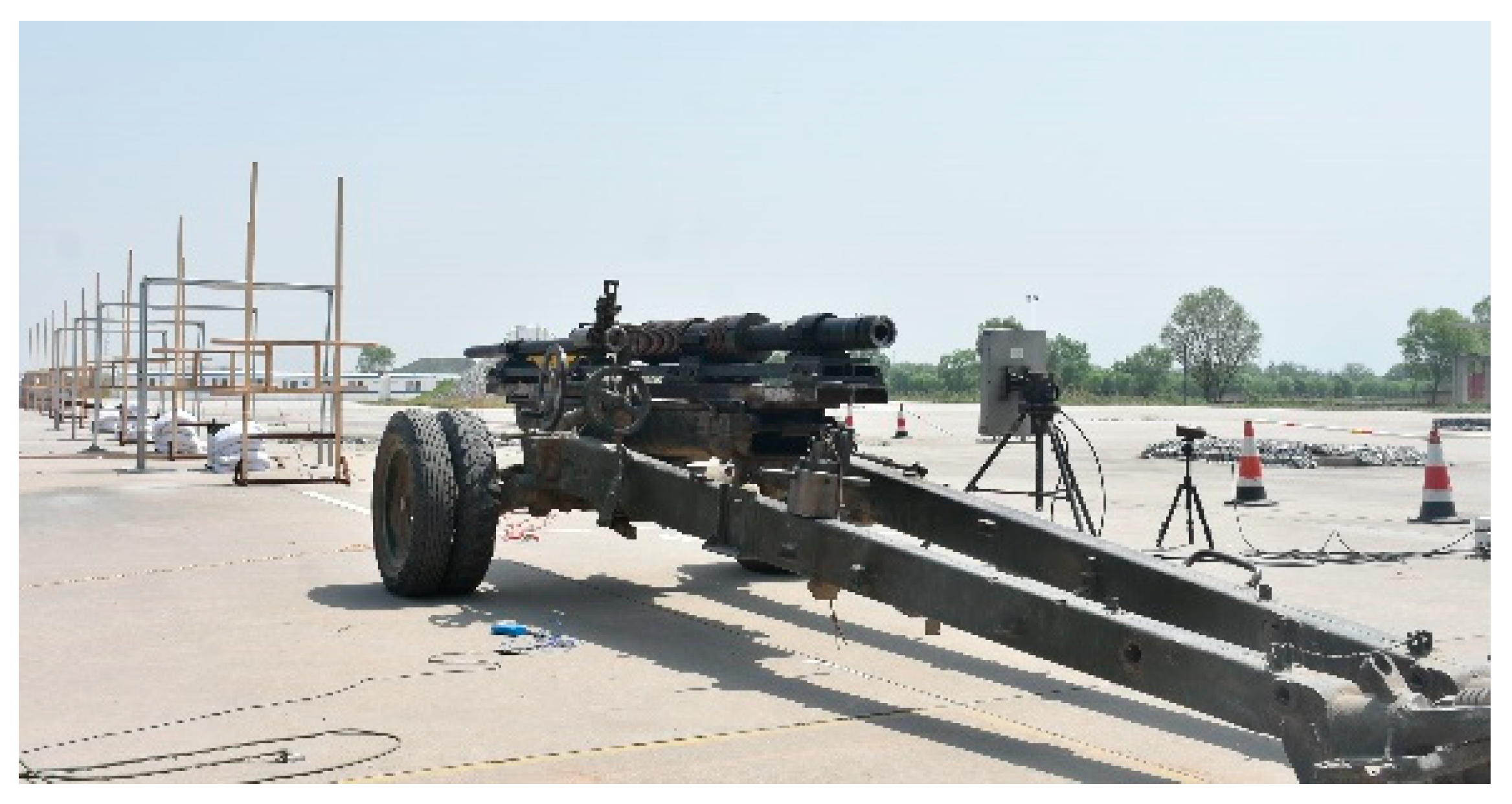
Figure 1. Schematic diagram of experimental system.
Applsci 12 09922 g001
Figure 2. Sub-caliber ultra-high speed fragment loading device.
Applsci 12 09922 g002
Figure 3. Size and shape of the experimental projectile.
Applsci 12 09922 g003
Figure 4. Pressure curve of the combustion chamber in the experiment.
Applsci 12 09922 g004
Figure 5. Flame evolution characteristics on the muzzle of the launching system.
Applsci 12 09922 g005
Figure 6. Movement process of the projectile. (a) t = 1.2 ms; (b) t = 1.4 ms.
Applsci 12 09922 g006
Figure 7. Movement process of the projectile.
Applsci 12 09922 g007
Figure 8. Velocity curve of the projectile in the tube. (a) v-l; (b) v-t.
Applsci 12 09922 g008
Table 1. Results of the tube strength.
No.Tube Length (mm)Pressure
(MPa)
Inner Diameter (mm)Outer Diameter (mm)σi
(MPa)
σe
(MPa)
nine
10~20040054130700.15166.821.496.23
2200~71531030120454.6741.332.2925.16
3715~96023030106346.7240.053.0025.97
4960~200018030100275.635.63.7729.21
52000~28508030100122.4915.828.4965.72
62850~356050308083.0316.3612.5363.56
73560~383038309060.179.517.29109.47
83830~427035307062.4215.7516.6666.03
94270~4500303060602017.3352
Table 2. The distance between group IVMDs and corresponding interval times.
No.Group IVMDsDistances (m)Interval Time (ms)Fragment Velocity (m/s)
11–46.2423.4981784.4
22–35.83.251784.6
34–56.84.0581675.7
45–85.1993.2951577.8
56–74.7553.0141577.6
Table 3. Comparisons of experimental and numerical results.
Grain
Configuration
Powder Charge(g)Muzzle Velocity (m/s)Maximum Pressure (MPa)
ExperimentSimulationExperimentSimulation
5/726017701844179178
5/730020802056263261
Table 4. Better optimization result.
No.Muzzle Velocity (m/s)Burning Rate CoefficientBurning Rate
Index
Gunpowder
Impetus (kJ/kg)
Distance between Adjacent Holes (mm)Diameter of Every Holes (mm)
12132.01.56 × 1080.8267975.10.300.25
22224.21.43 × 1080.8299991.30.370.23
32299.51.70 × 1080.8245958.40.380.22
42303.81.64 × 1080.8283905.10.220.21
52315.81.69 × 1080.8273917.30.250.22
62342.31.54 × 1080.8284967.80.360.21
72362.81.73 × 1080.8298950.70.230.24
82373.61.72 × 1080.8268967.20.240.23
Publisher’s Note: MDPI stays neutral with regard to jurisdictional claims in published maps and institutional affiliations.