Article

Battery Energy Storage Participation in Automatic Generation Control of Island Systems, Coordinated with State of Charge Regulation

by
Apostolos G. Papakonstantinou
* and
Stavros A. Papathanassiou
School of Electrical and Computer Engineering, National Technical University of Athens (NTUA), 15773 Athens, Greece
*
Author to whom correspondence should be addressed.
Appl. Sci. 2022, 12(2), 596; https://doi.org/10.3390/app12020596
Submission received: 5 December 2021 / Revised: 27 December 2021 / Accepted: 7 January 2022 / Published: 8 January 2022

Abstract

:
Efficient storage participation in the secondary frequency regulation of island systems is a prerequisite towards their complete decarbonization. However, energy reserve limitations of storage resources pose challenges to their integration in centralized automatic generation control (AGC). This paper presents a frequency control method, in which battery energy storage systems (BESSs) participate in automatic frequency restoration reserve (aFRR) provision, through their integration in the AGC of an island system. A local state of charge (SOC) controller ensures safe operation of the BESS in case of disturbances, without jeopardizing system security when available energy reserves are diminishing. The aFRR participation factors of regulating units are altered when the storage systems approach their SOC limits, re-allocating their reserves to other load-following units. Restoration of BESS energy reserves is achieved by integrating SOC regulation in the real-time economic dispatch of the system, formulated as a mixed-integer linear programming problem and solved every few minutes to determine the base points of the AGC units. A small autonomous power system, comprising conventional units, renewable energy sources and a BESS, is used as a study case to evaluate the performance of the proposed method, which is compared with alternative approaches to secondary regulation with BESS participation.

1. Introduction

Energy storage systems (ESSs) are capable of providing a wide array of services, including arbitrage, resource adequacy enhancement, congestion management, reduction of renewable energy source (RES) curtailment and frequency and voltage regulation [1,2,3]. RES integration in autonomous systems necessitates increased storage capacities, among other things, to manage curtailments at low load periods [4,5]. Substantial research is available regarding benefits afforded by storage in terms of unit scheduling and load dispatch, RES hosting capacity and resource adequacy in islands grids [5,6,7,8,9]. The low inertia of autonomous systems [10] amplifies the need for fast-acting storage units, with battery energy storage systems (BESSs) being the most appropriate technology, given the water column dynamics limitations inherent in pumped hydro facilities [11,12]. Li-ion is the prevailing technology, due to ease of deployment, high energy and power density, high lifetime expectancy, low self-discharge and continuous cost reduction [13,14], making them ideal for small- and medium-scale non-interconnected grids. With the accelerated decarbonization of the electricity sector, the introduction of fast response energy storage is considered as a key enabler to support the transition towards a generation mix dominated by stochastic RESs. Beyond autonomous island systems, energy storage brings considerable advantages in several applications including residential, industrial and commercial facilities, e.g., [15,16,17,18]. Enhancing the power management efficiency of seaports is another storage application field, attracting increasing research interest [3]. Electromobility constitutes another principal application field for batteries, where substantial research is taking place, including on optimum power management and battery design and sizing [19].
Focusing on electric power systems, the contribution of RES units to frequency control via droop and inertial emulation is well established in the literature [20,21,22,23]. Similar control principles have been applied to BESSs, taking into consideration state of charge (SOC) limits, to avoid battery degradation [14,24,25,26,27,28,29,30,31]. In [25,26], the authors present a method increasing the storage droop coefficient, when SOC is outside its normal range, while, in [26], another method is also proposed, superposing a charging/discharging term and the droop control. Tan et al. [30] propose SOC restoration to take place when the frequency regulation task permits, i.e., when frequency deviations are limited, whereas regulation is prioritized when deviations are large. The need for imposing constraints in SOC restoration, taking account of available system reserves, is noted in [30], as well as the existing gap in the literature on coordinating frequency and SOC regulation. Boyle et al. [31] propose a fuzzy logic controller for SOC restoration when the energy reserves are close to 50%, while using a different scheme (PI control of SOC) for larger SOC deviations.
BESS participation in load–frequency control (LFC), traditionally referred to as secondary regulation or deployment of automatic frequency restoration reserves (aFRR) [32], has received less attention. The intermittency of RES generation leads to the increase in aFRR system needs [33]. Enabling effective storage participation in the provision of aFRR reduces the burden placed on conventional power plants and eventually the balancing cost of the system, whilst enhancing frequency stability [5,34,35]. As noted in [23], there is room for further improvement in effective coordination between generating and storage units to implement primary and secondary frequency regulation, especially in isolated systems.
In [36,37,38,39], an automatic generation control (AGC) system is implemented allocating slow active power variations to conventional units and faster ones to battery systems. A similar control principle is also followed by PJM [10]. Zhang et al. [39] propose a fuzzy controller for the allocation of the fast-varying power reference to individual units in a group of BESS stations, based on techno-economic criteria. Although effective, these methods do not facilitate storage participation in aFRR economic scheduling on equal terms with conventional units. In [40], the proposed AGC scheme allocates BESS capacity to secondary frequency regulation, also considering their minute-level charge/discharge capability. Cheng et al. [40] note that distributing the AGC regulation signal to participating units based on pre-defined fixed allocation percentages is ineffective when BESSs are participating in secondary frequency regulation due to SOC management limitations.
Doenges et al. [41] propose a BESS control strategy reducing the rate of non-compliance to AGC signals in a regulation area. A similar SOC regulation method is also used in [38,42]. In all three papers, BESS charge/discharge is restricted, once energy reserves in the batteries reach their minimum/maximum limits. A “conditional neutrality controller” is applied by PJM, to restore the energy reserves of storage units, estimating SOC based on the timeseries of commands dispatched to the units and applying proportional SOC control, whose gain is adjusted depending on the SOC level [10]. The resulting SOC regulation term modulates the reference point of conventional resources [10]. In [43,44], an LFC scheme is presented where battery systems compensate for the low ramping capabilities of conventional units through a continuously active battery SOC controller, regulating battery output in parallel to the AGC.
References [45,46] study the participation of storage in standard LFC schemes, with the latter proposing an adjustment of the ESS setpoint every 15–60 min, according to the energy injected/absorbed. However, such a SOC regulation method does not consider the effect that ESS setpoint variations may have on system reserves; this factor is taken into account to a certain extent in [47], where the BESS active power reference is given by the superposition of a frequency containment reserve (FCR) term and an appropriately capped charging/discharging reference (e.g., at 20% of rated capacity). The negative impact on frequency regulation when an ESS participating in LFC reaches its SOC limits is noted in [35], indicating the need to consider SOC regulation under such circumstances, which needs to be incorporated in the central AGC system to avoid a detrimental effect on frequency stability.
Chang et al. [48] propose a hierarchical control for isolated systems dominated by ESSs, where multiple battery systems participate in isochronous frequency control, while diesel units do not participate in LFC, but regulate the SOC of the storage units. A similar approach is described in [49], where a BESS operates in grid-forming mode, thus completely taking up system power equilibrium maintenance, with its SOC regulation being performed by a diesel generator. Both [50] and [51] deal with the support that an ESS system can provide to RESs participating in reserve provision. Datta et al. [50] propose a fuzzy control method for a BESS to support participation of photovoltaics (PVs) in LFC, without, however, addressing SOC regulation, whereas the support of a wind farm in the provision of frequency-related reserves is addressed in [51], also applying an adaptive state-of-charge regulation scheme. In [52], BESSs provide solely secondary frequency regulation, via a fuzzy logic controller regulating energy reserves when frequency is near its nominal value. However, the SOC restoration consumes secondary reserves provided by other units. Hosseinzadeh et al. [53] propose a control scheme for an isolated AC-DC microgrid, in which a fuzzy-logic controller is regulating BESS power output, taking account of their SOC and the power deficit/surplus of each microgrid. Although effective, this approach is not applicable to standard central AGC systems, is complex in its practical implementation and it is non-scalable to large-scale interconnected systems. Moreover, in such a scheme the batteries do not participate on equal terms with other units—via a market-based mechanism—in the secondary regulation of the system. Control methods with significantly higher complexity addressing SOC regulation and participation of energy storage in LFC are also available in the literature, e.g., H control [54], whose implementation in real-world power systems is rather challenging.
In this paper, an active power control scheme is proposed for batteries in island systems to provide secondary frequency regulation, along with inertia emulation and droop response. SOC regulation is implemented through a local controller, continuously supervising SOC to ensure it remains within acceptable limits, with its restoration back to its reference being effected within the real-time economic dispatch process. To achieve frequency restoration, the BESS is integrated in a centralized AGC system that dynamically redistributes the total regulation signal to all load-following units, whilst considering participation factors coming from the electricity market, as well as the SOC of the BESS.
The proposed method allows batteries to participate in secondary regulation delivered through a centralized AGC system and driven by economic dispatch, while incorporating charge management functionality to prevent battery energy reserve depletion, particularly in challenging situations, when energy reserves are depleted while BESSs are providing secondary control. The questions addressed include how to minimize the impact on secondary regulation, as well as how to prevent SOC restoration from placing an excessive burden on system reserves provided by other regulating units. Building upon existing work on BESS participation in secondary regulation, this paper presents a complete solution in the time scale of seconds to minutes, consisting of an economic dispatch module, executed every 15 min to derive optimal loading base points for all units, a centralized AGC system generating regulating signals for load-following units every few seconds and continuously acting local BESS controllers to execute AGC signals while providing primary frequency control and charge management. Unlike other schemes presented in the literature, the proposed method is simple, scalable and easy to apply in real-life systems, its tuning is undemanding and it is compatible with different market and regulation environments.
The introduction of such a method constitutes the novelty and the main contribution of this paper, which is significant and timely given the momentum of grid storage and the anticipation that battery systems will fully participate in regulation and control. To validate its performance and demonstrate its advantages, the proposed method is compared with three alternative regulation approaches, using as a study case a small island system.
The paper is organized as follows: The proposed method, along with three alternative regulation methods, are described in Section 2. Section 3 presents the real-time economic dispatch problem. The study case island grid is described in Section 4. In Section 5, simulations results are presented and discussed, leading to the conclusions summarized in Section 6.

2. Frequency and Active Power Control Schemes

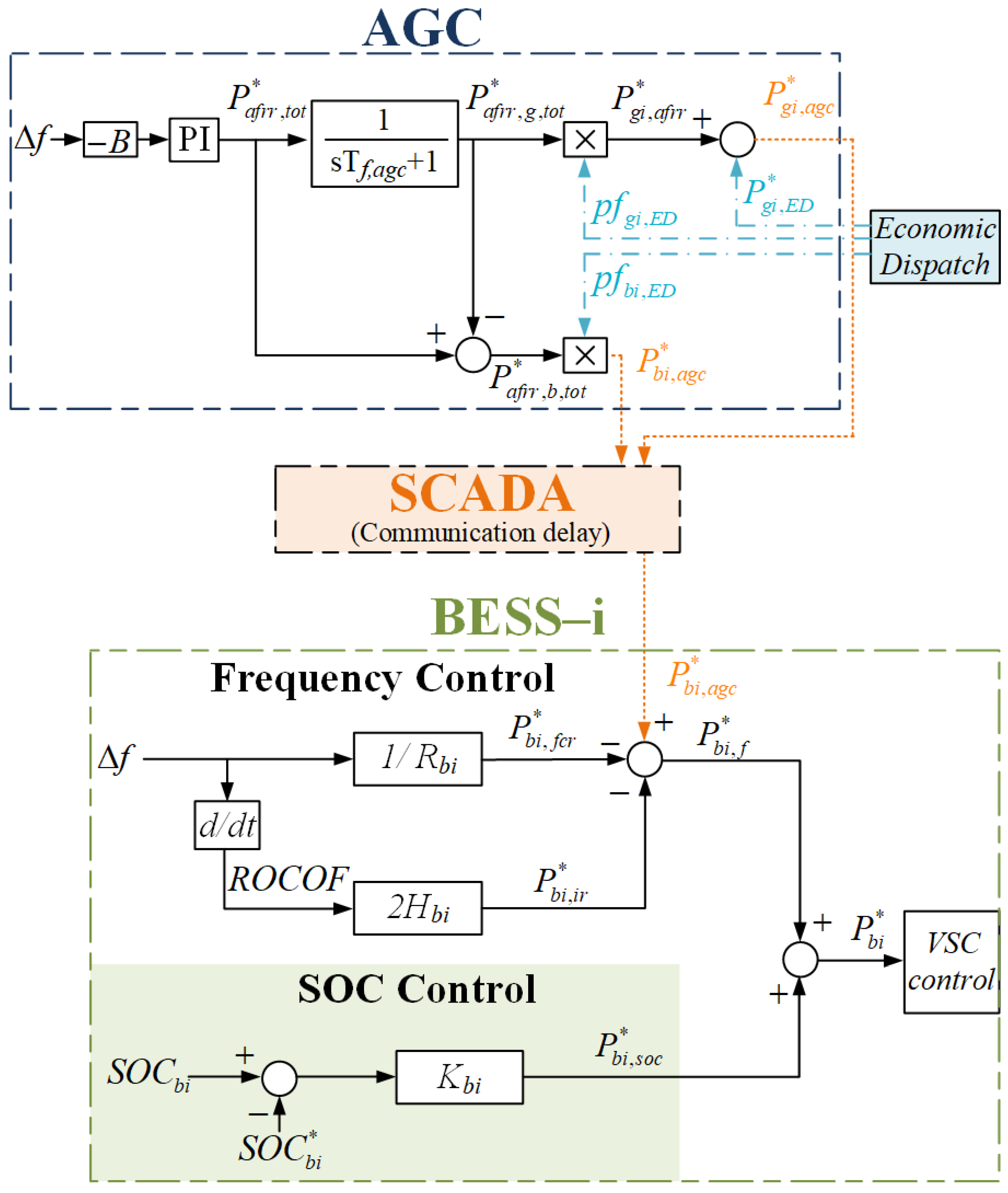
2.1. Proposed Method

The active power regulation scheme proposed in the paper is illustrated in Figure 1. The local BESS controller consists of two modules, the frequency regulation and the SOC control (in green). Links to the supervisory control and data acquisition (SCADA) system are shown with an orange dotted line; signals from the economic dispatch module (described in Section 3) are shown with a blue dash-dotted line.
For simplicity, a single energy storage system is assumed in the schematic diagrams of this section and in the simulation results presented in Section 5. The control principles can easily apply when dealing with multiple independent storages, by applying the local BESS controller of Figure 1 to each unit, without any further change needed to the algorithms of the central AGC system or the economic dispatch module presented in Section 3. For this reason, the subscript “bi” is used in BESS parameters to include the general case of having more than one independently controlled battery units in the isolated grid.
The output of the frequency control module, P b i , f * , is formulated by the superposition of three terms: P b i , f c r * and P b i , i r * representing droop (Rbi) and inertia emulation (Hbi), respectively, and the AGC dispatch order P b i , a g c * . Dispatch orders ( P g i , a g c * , P b i , a g c * ) are formed by superposing secondary regulation terms ( P g i , a f r r * ,   P b i , a f r r * ) on the economic dispatch (ED) base points ( P g i , E D * ,   P b i , E D * ) . Although more sophisticated secondary regulation schemes are available in the literature [55], a standard AGC scheme is chosen here as a basis, to develop a method widely applicable, scalable and easy to implement. A time delay of 1 s is assumed in data transmission between regulating units and the AGC system, as noted in Table A2 of Appendix A. All necessary filtering, dead bands and rate limiters are omitted in Figure 1 for the sake of clarity, but are described in Table A2 of Appendix A, for reproducibility purposes.
In Figure 1, parameter B stands for the bias factor ( B = g i G 1 / R g i + b i E S S 1 / R b i ), described in detail in [11,55]. G and ESS are the sets of conventional units and storages, respectively. A proportional integral (PI) controller regulates the frequency deviation to zero. The total aFRR ( P a f r r , t o t * ) is allocated to regulating units according to their participation factors pfgi and pfbi, which sum to unity in both directions (upwards and downwards). Participation factors pfgi,ED and pfbi,ED, determined in the scheduling process, are modified in real-time operation according to Equations (1) and (2) to account for the SOC regulation, as explained latter in this section.
SOC needs to be supervised and regulated within its normal variation range, to avoid a detrimental effect on battery life, especially when BESSs participate in the provision of aFRR. In this paper’s implementation, SOC is regulated within the economic dispatch process, as explained in Section 3, to ensure sufficient energy reserves for sustained FCR and aFRR provision, in an economically optimal manner. Nevertheless, battery safety dictates that SOC monitoring and regulation are also implemented at the local battery system level, modulating its output power as needed. To this effect, the term P b i , s o c * is included in Figure 1, ensuring that SOC remains close to its reference S O C b i * , using a proportional (P) controller. SOC control is only activated when the SOC range limits are approached, as shown in Figure 2. Minimum (SOCbi,min−SOCbi,min+) and maximum (SOCbi,max−SOCbi,max+) zones are defined, allowing gradual activation of the SOC regulation module, according to coefficients cbi,up (green) and cbi,dn (red). As illustrated in Figure 2, cbi,up > 0 while SOCbi < SOCbi,min+ and cbi,dn > 0 while SOCbi > SOCbi,max−. The term P b i , s o c * is then superimposed on the output of the frequency regulation module P b i , f * , to prevent BESS under/over-charging. This imposed deviation of BESS output from the AGC command, as well as cbi,(up/dn), are fed back into the AGC to modify the participation factors of all units according to Equations (1)–(3), thus preventing any impact on secondary frequency regulation. Equations (1)–(3) are used distinctly for upwards participation factors’ calculations (using the subscript “up”), and downwards participation factors’ calculations (using the subscript “dn”). The upwards (downwards) BESS aFRR participation factor is affected only by cbi,up (cbi,dn), since high (low) BESS energy reserves do not restrict its upwards (downwards) secondary reserve provision capability.
p f b i , ( u p / d n ) = ( 1 c b i , ( u p / d n ) ) p f b i , E D , ( u p / d n ) 1 c b i , ( u p / d n ) p f b i , E D , ( u p / d n ) ,   b i E S S
p f g i , ( u p / d n ) = ( 1 b i E S S p f b i , ( u p / d n ) ) p f g i , E D , ( u p / d n ) g i G p f g i , E D , ( u p / d n ) ,   g i G
p f g i , n o e s s , ( u p / d n ) = p f g i , E D , ( u p / d n ) g i G p f g i , E D , ( u p / d n ) ,   g i G
In the simulations presented in Section 5, it is assumed that the state of charge of each storage unit should be maintained within 20–90% (similarly as in [14,39,52,56]), thus SOCbi,min− and SOCbi,max+ are set at these values (see Table A2). Selection of SOCbi,min+ and SOCbi,max− parameters defines the SOC edge intervals where the battery has only partial contribution to frequency regulation. Selection of relatively high SOCbi,min+ and low SOCbi,max− values will reduce battery degradation and provide a smoother response in SOC edge intervals, but at the same time will result in under-exploitation of BESS regulation capabilities and reserves. In this work, a 5% range is considered sufficient, thus SOCbi,min+ and SOCbi,max− are set to 25% and 85%, respectively. A parametric evaluation is presented in Section 5.2.2, to show the effect of SOCbi,min+ on the performance of the proposed control method.
Given the slow dynamics of SOC change, a simple and straightforward tuning process is proposed for Kbi: With reference to Figure 1, a SOC level is defined where P b i , s o c * will always cancel P b i , f * , to exclude discharging below that SOC. To observe this requirement, Kbi is selected such that P b i , s o c * = 1 pu at the specified SOC level. For example, if SOCbi,min− = 20%, SOCbi,min+ = 25%, and half of the SOC control activation zone (2.5%) is used as a safety margin against hitting SOCbi,min−, then P b i , s o c * = 1 pu when SOC drops to 22.5%. Assuming S O C b i * = 55%, as noted in Section 3, this (i.e., P b i , s o c * = 1 pu for SOCbi = 22.5%) is achieved by setting K b i = 1 c b i , u p ( S O C b i * S O C b i ) = 1 0.5 ( 55 22.5 ) = 0.0615 , which is the value used in the simulations in Section 5. The same tuning process can be followed around maximum SOC. A Kbi parametric analysis is presented in Section 5.2.1.
The implementation of the proposed method requires that at least one more regulating unit is on-line to undertake part of the aFRR provided from the BESS, according to Equations (2) and (3), whenever its energy variation margins are depleted (SOCbi < SOCbi,min+ or SOCbi > SOCbi,max−). For this reason, a maximum BESS participation factor is proposed as a constraint in the dispatch scheduling problem. Such a limitation might be useful to ensure availability of energy reserves in storage units, as concluded by Zhang et al. [35]. As noted in [57], if action is not taken before SOC reaches its limits, the BESS would suddenly shut down by its battery management system (BMS), possibly resulting in a critical situation for the system.
Although an island system is used as a study case, the proposed coordinated active power control method is also applicable in large-scale interconnected power systems (where tie-line power flows will also enter in area control error formation), without losing its simplicity and minimum signals/control modules required. In fact, the proposed method is built upon an established standard AGC scheme implemented in power systems around the world. The required real-time calculations of participation factors using Equations (1)–(3), as well as of the term P g i , a f r r , s o c * , are simple and straightforward, while the three required signals per storage station ( P b i , s o c * , c b i , u p , c b i , d n ) add no burden to the SCADA infrastructure. The need for storage systems to transmit SOC-related information to the system operator is already established in grid codes of island systems (e.g., Cyprus, [58]). The proposed local BESS controller is also easy to implement, as it only requires a SOC measurement, already available to the BMS, and very simple calculations.
The BESS converter controller is illustrated in Figure 3. More detail is provided in [59]. The BESS active power reference ( P b i * ) comes from the local BESS controller of Figure 1, while the reactive reference is the output of a proportional voltage controller. Between the two, active power is prioritized in the current limiting module, although this could be reverted, depending on system needs. BESS current limits are dictated by its rated capacity, as well as by its BMS monitoring various operating parameters. An L filter is used to interface the voltage source converter (VSC) to its output step-up transformer.

2.2. Alternative aFRR Participation Methods for BESS

To demonstrate the effectiveness of the proposed control scheme, three alternative methods of BESS participation in the aFRR process are briefly presented in the following section and are further simulated in Section 5.1.

2.2.1. Filter-Based AGC

The principle behind the “filter-based AGC” method is that battery systems take up the fast-varying components of secondary regulation, while thermal units follow slow-varying dispatch orders for load-following purposes. Variants of this AGC control strategy are proposed in papers [36,37,38,39], using either a low pass filter or rate limiters to derive the regulating signals for thermal units. A proportional SOC control proposed in [36,37] is implemented at the local BESS level, to ensure energy reserves. Figure 4 illustrates the schematic diagram of the filter-based AGC method. A 1 min time constant is chosen for the AGC filter (Tf,agc = 60 s) to maximize battery utilization. As in [36,37], BESSs are not participating in the economic dispatch of the system, since their SOC is regulated through the always active p-controller. The participation factors of thermal units (pfgi,ED) sum to unity; the same holds for the participation factors of battery systems (pfbi,ED) [37].

2.2.2. BAU SOC Control

The business-as-usual (BAU) SOC control method is demonstrated in Figure 5. In this scheme, batteries participate on equal terms with thermal units on secondary frequency regulation, as well as in the ED problem of Section 3. When the SOC approaches its limits (SOCbi,min,BAU or SOCbi,max,BAU), the BESS will go into idling ( P b i * = 0 ) or provide regulation only in the direction of SOC restoration to its reference through P b i , f * , e.g., in low-charge conditions, the battery active power will only track a recharging reference ( P b i , f * < 0 ), else it will remain zero. The transitions between idling state (zero power) and a non-zero P b i , f * are rate limited (at 0.1 pu/s). Moreover, a safety margin of 2.5%, as in the proposed method, is used in selecting SOCbi,min,BAU, and SOCbi,max,BAU in relation to SOCbi,min− and SOCbi,max+ (see Table A2). Through the rate limiter and the SOC safety margins, smooth switching between rules is achieved. In this simple power control scheme, the AGC does not incorporate any SOC- or power-related signals from the BESS station.

2.2.3. SOC Control with No AGC Communication

This method is a combination of the “BAU SOC control” and the proposed method. The local BESS controller is as in the proposed method (Figure 1), the AGC is identical to the one used in the BAU SOC control scheme (Figure 5), but the regulating parameters of the local BESS controller ( P b i , s o c * , cbi,up, cbi,dn) are not fed back to the AGC. The purpose of this method is primarily to demonstrate the importance of communicating battery parameters cbi and P b i , s o c * to the AGC.

3. Economic Dispatch Process

The SOC controllers described in Section 2 ensure that SOC limits are always met, even in system disturbances. SOC restoration to its reference value, on the other hand, is incorporated in the real-time economic dispatch (ED) process. This is formulated as a mixed integer linear programming (MILP) optimization problem, executed almost in real time, typically every 1–15 min, resulting in dispatch orders ( P i , E D * ) and participation factors (pfi,ED) for all dispatchable units. Its goal is to minimize system cost in the respective time interval, whilst respecting the units’ technical constraints, commitment status and allocated reserves. The detailed description of this process for non-interconnected island systems can be found in [6,60], which formed the basis for the ED process implemented in this paper. The day-ahead or intra-day scheduling process resulting in the commitment status and reserve provision is not addressed in this paper. In terms of notation, lowercase letters are used in this section for decision variables and uppercase for parameters.
The objective function to be minimized in the ED process is:
J = ( g i G ( V C g i p t g i ) + i { G , E S S } ( C u p s l , r r u p , t i , s l + C d n s l , r r d n , t i , s l ) + C s l , e q p t s l , e q ) Δ t + C s l , s o c b i E S S ( ( s o c u p , t b i , s l + s o c d n , t b i , s l ) E b i , m a x )
where G is the set of conventional generators, ESS is the set of storage units, ri,sl, pi,sl and socbi,sl are the slack variables explained later in this section, Δt is the ED time interval (in hours) and Ebi,max is the ESS maximum energy capacity of each independently controlled storage unit. The first term of Equation (4) is the thermal unit variable production cost. Variable cost (VCgi) in €/MWh will depend on the production level ( p t g i ) of each thermal unit. Here, for simplicity, a constant VCgi is assumed for all units. The following two terms penalize deviations in available reserves and in the active power equilibrium of the system, while the last term penalizes SOC deviations from its reference value. High Csl,soc will over-prioritize SOC regulation, whereas low cost values may not prevent BESS energy depletion. The following relative priority of constraints is chosen: C s l , e q > C u p s l , r > C d n s l , r > C s l , s o c > V C g i (all in €/MWh).
The power equilibrium constraint is given by:
g i G p t g i + b i E S S p t b i , d + p t r e s + p t s l , e q = P t L + b i E S S p t b i , c
In (5), p t b i , d and p t b i , c are the ESS discharge and charge, respectively, p t r e s is the aggregate RES production and P t L the system load. The power equilibrium slack variable ( p t s l , e q ) ensures the feasibility of the solution.
The technical constraints of conventional units given in Equations (6) and (7) result in retaining the reserves ( F C R u p / d n , t g i , a F R R u p / d n , t g i ) allocated in the scheduling process, while leaving room for exceptional cases where this is not feasible, via the introduction of two slack variables ( r u p , t g i , s l ,   r d n , t g i , s l ) . The commitment status of thermal units ( s t t g i ) is a parameter in the ED problem, coming from the dispatch schedule. Constraint (8) ensures zero output for unsynchronized units ( s t t g i = 0 p t g i = 0 ) , even when the slack variable r u p , t g i , s l takes non-zero value. Ramping constraints are normally part of the ED problem, however, they are not important in small island systems, such as the study case of this paper, due to the high ramping capability of small diesel units.
p t g i + F C R u p , t g i + a F R R u p , t g i s t t g i P g i , max + r u p , t g i , s l , g i G
p t g i F C R d n , t g i a F R R d n , t g i s t t g i P g i , min r d n , t g i , s l , g i G
p t g i s t t g i P g i , max , g i G
p f u p / d n , t i = a F R R u p / d n , t i i { G , E S S } a F R R u p / d n , t i , i { G , E S S }
aFRR participation factors ( p f u p / d n , t i ) sent to the AGC are calculated using Equation (9), according to the scheduling process results. Calculation practices for participation factors, taking account of unit ramp rates, variable costs and capacity, are described in [11,12,41,55,61,62].
RES generation curtailment ( x t r e s ) is calculated using Equation (10), where P t r e s , m a x is the available RES generation.
p t r e s + x t r e s = P t r e s , max
Constraints (11)–(17) are associated with the operation of the energy storage systems. Using the integer state variables ( s t t b i , c ,   s t t b i , d ) in (11), the case of simultaneously charging and discharging storage units is avoided. Storage constraints (12) and (13) are equivalent to (6) and (7) of thermal units, where Pbi,d,max and Pbi,c,max refer to the maximum discharge and charge capacity, respectively. The charge/discharge states ( s t t b i , c ,   s t t b i , d ) are defined using constraints (14) and (15). Equation (16) calculates the SOC at the end of the ED time interval ( s o c t b i ) , using the expected SOC at the end of the previous time interval ( S O C t 1 b i ) , the dispatch orders ( p t b i , c ,   p t b i , d ) , the charging/discharging efficiency (nbi,c, nbi,d), the maximum energy capacity (Ebi,max), and the ED time interval duration, in hours (Δt).
Due to its short optimization horizon, the ED process cannot be relied upon to determine the optimal operation of limited energy resources. For this purpose, a reference SOC ( S O C t b i * ) is used as an input to the ED problem, which may be fixed or derived from a scheduling process executed at a previous step, with a longer optimization horizon (e.g., daily). Dealing with short-duration storages (e.g., 1 h), as in the study case of this paper, energy arbitrage is not part of their intended functionality, which is the provision of operating reserves. In such a case, the objective is to maintain energy reserves at a level that ensures sustained provision of FCR and aFRR for a minimum duration. Hence, in this paper, a constant S O C t b i * reference is assumed, set at 55% (see Table A1 of Appendix A) to ensure both an upwards and downwards regulation capability.
Equation (17) is introduced in the ED process, in order to penalize SOC deviations (using Equation (4)), expressed through slack variables ( s o c u p , t b i , s l ,   s o c d n , t b i , s l ) , from its reference. Thus, SOC is restored back to its reference in each ED interval, replenishing energy reserves utilized to support reserve deployment in real time. This process will not put system security at risk, as constraints (6) and (7) ensure that SOC regulation observes the level of reserves available by the thermal units.
s t t b i , d + s t t b i , c 1 ,   b i E S S
p t b i , d + F C R u p , t b i + a F R R u p , t b i P b i , d , m a x + p t b i , c + r u p , t b i , s l ,   b i E S S
p t b i , c + F C R d n , t b i + a F R R d n , t b i P b i , c , m a x + p t b i , d + r d n , t b i , s l ,   b i E S S
p t b i , d s t t b i , d P b i , d , m a x ,   b i E S S
p t b i , c s t t b i , c P b i , c , m a x ,   b i E S S
s o c t b i = S O C t 1 b i + ( n b i , c p t b i , c p t b i , d / n b i , d ) Δ t E b i , m a x ,   b i E S S
s o c t b i + s o c u p , t b i , s l s o c d n , t b i , s l = S O C t b i * ,   b i E S S
Overall, implementing SOC restoration within the ED process, rather than in the AGC or in the local controllers of storage units, is beneficial for system security, as charging/discharging is integrated in the overall system management, given the appropriate level of priority and respecting availability of FCR and aFRR.

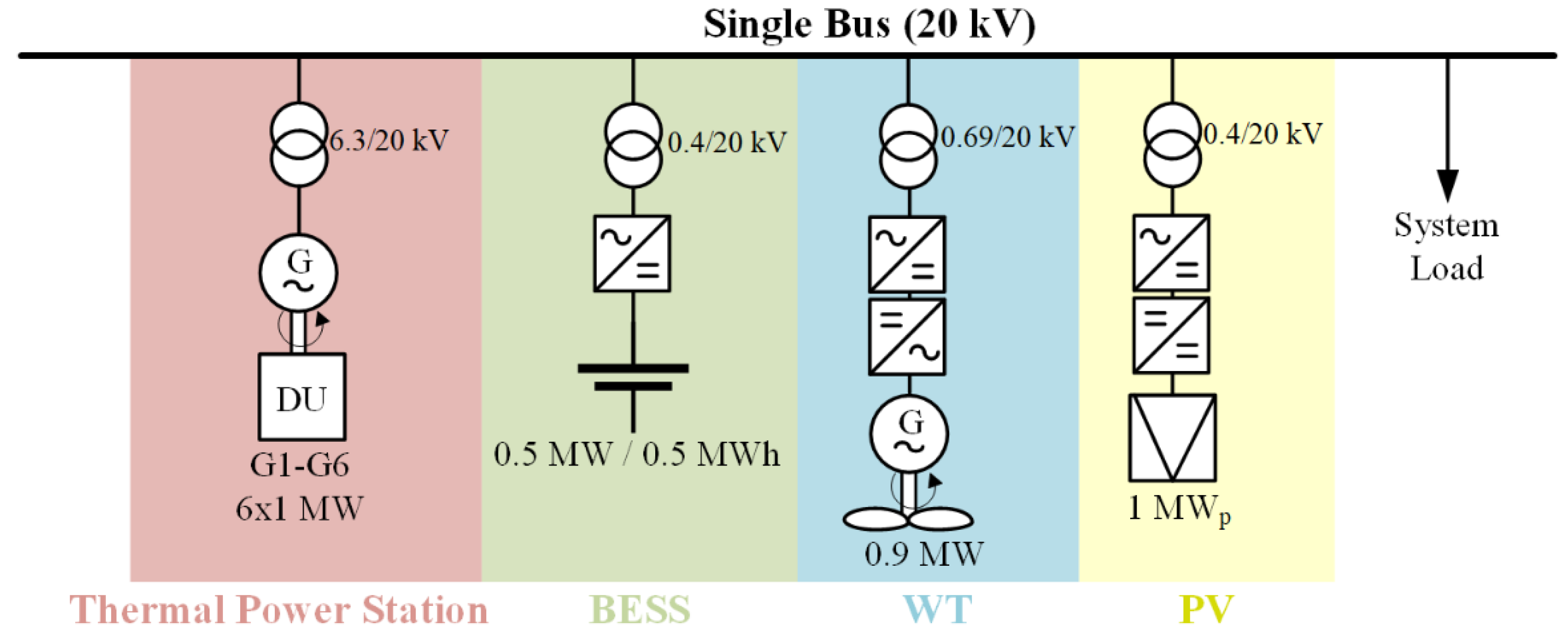
4. Study Case System

The proposed BESS participation model is simulated in the small island grid presented in Figure 6, consisting of (a) a thermal power station comprising 6 × 1 MW diesel units (DUs), (b) a 0.5 MW/0.5 MWh BESS, (c) a 0.9 MW wind turbine (WT), (d) a 1 MWp PV plant and (e) the system load. The six identical diesel units are modeled according to [63], including the non-linearities of the turbocharged prime movers, and a typical DU governor model (DEGOV1) [64,65], to capture the frequency response characteristics of the autonomous system. The 0.5 MW/0.5 MWh Li-ion BESS allows for a 1 h discharge time at rated power within its permissible SOC range (SOCb,min−SOCb,max+). Details on the battery model used can be found in [66]. The battery cycles are used as a simple degradation indicator in time-domain simulations, calculated based on the energy throughput of the batteries, as in [56]. A SOC variation from SOCb,max+ (90%) to SOCb,min− (20%) and back is equivalent to one full cycle.
A pitch controlled, full-power converter WT is considered, whose MPPT module is based on a static optimum power–speed curve and a PI speed controller [67,68,69]. The PV system is simulated as in [22] and operated in MPPT mode. The load damping is considered negligible, due to the small scale of the electrical system [70]. The system parameters used for the simulations are summarized in Appendix A (Table A1 and Table A2).

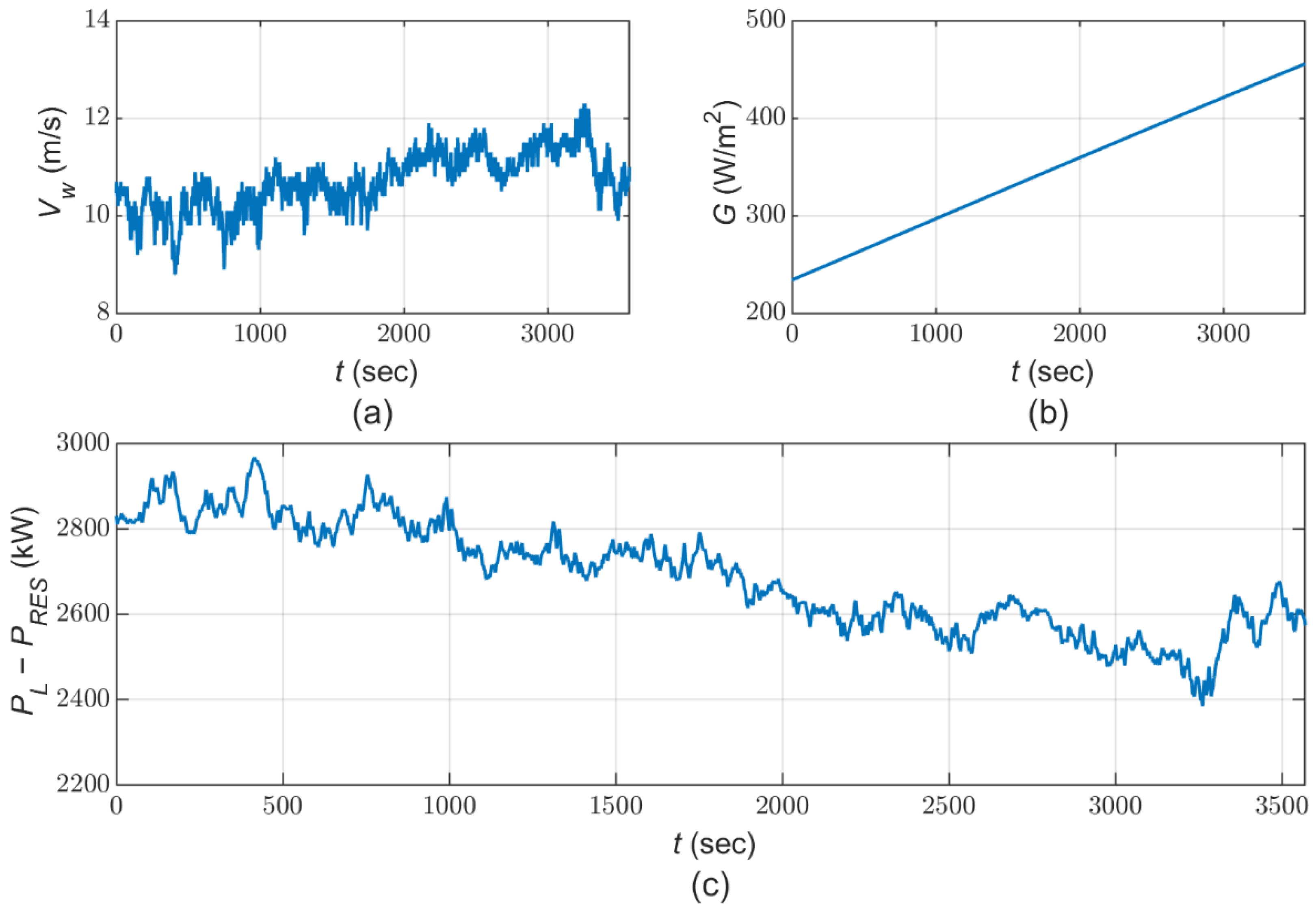
5. Simulation Results

Time-domain simulations were carried out using MATLAB/Simulink, with a positive-sequence phasor model implementation, that is sufficient to capture the frequency control dynamics of the studied system. The ED problem, providing dispatch orders and participation factors (PED and pfED) to the AGC, is executed using the Gurobi optimization solver in Python. Its timeframe is chosen equal to 15 min.
System response is simulated over an interval of one hour, using the wind and solar radiation timeseries depicted in Figure 7a,b. The resulting residual load (load-RES), supplied by the dispatchable units (DU and BESS), is shown in Figure 7c and corresponds to a constant load of 3.5 MW. No RES curtailments take place under the simulation conditions.
Four (4) diesel units (of 1 MW each) are on-line in the beginning of the simulation interval. One diesel unit (G4) trips at t = 150 s, followed by the synchronization of another unit (G5) 12.5 min after the contingency. A 30% initial charging level is assumed for the BESS, to study the response of the system when the battery SOC reaches the activation zone of the proposed method.

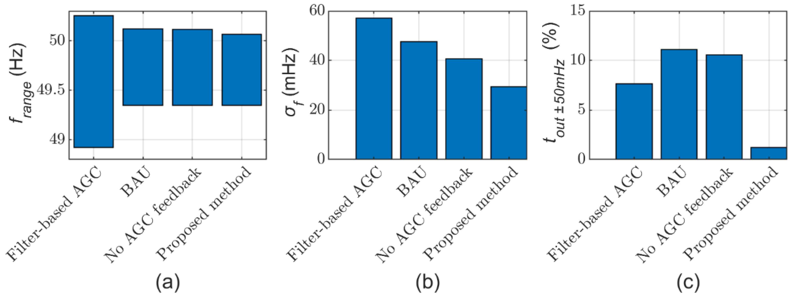
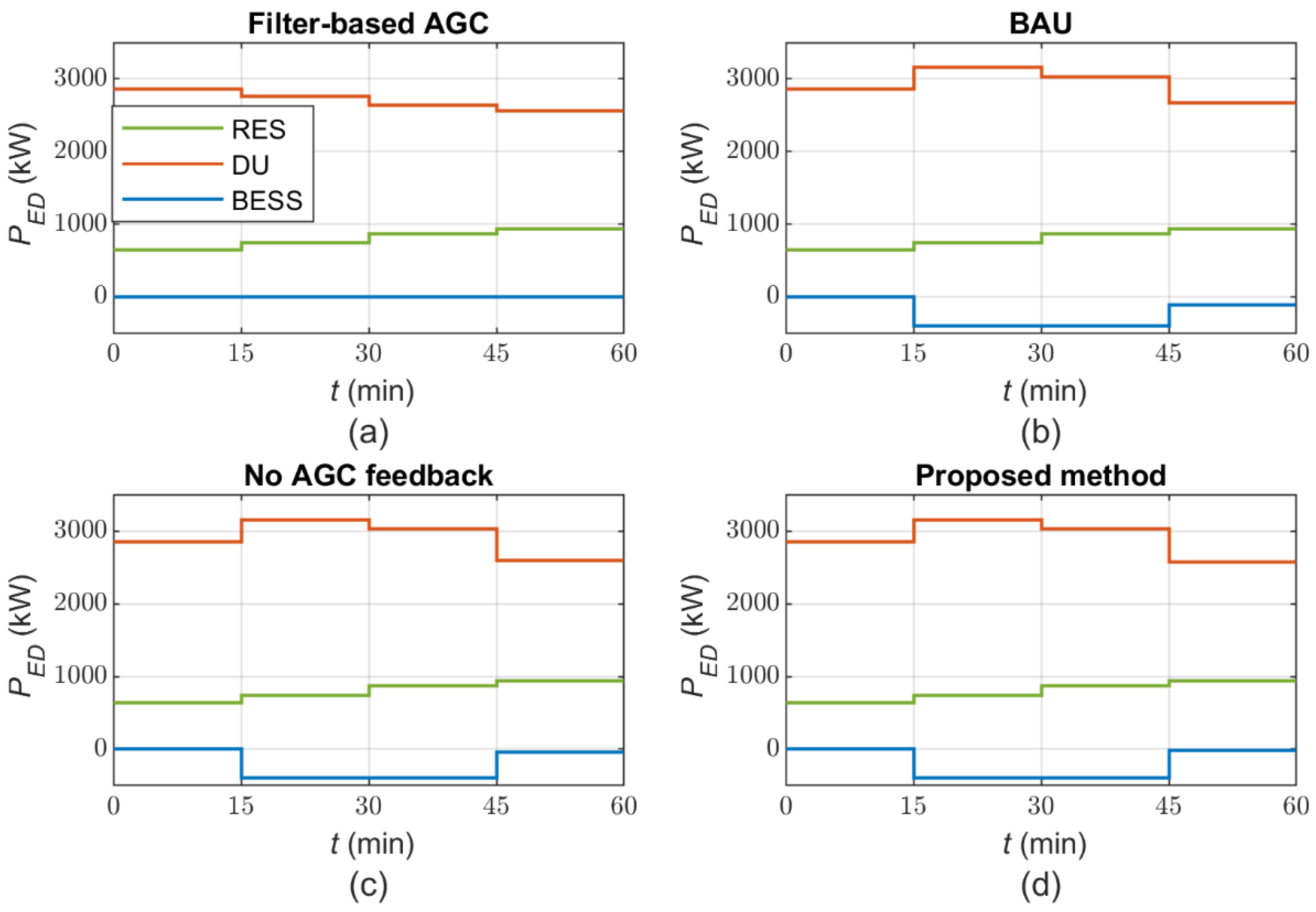
5.1. Comperative Assesment of Different Power Control Schemes

Time-domain simulation results in Figure 8 show the response of the system in the following cases:
(i)
Filter-based AGC (Section 2.2.1)—red dash-dotted line.
(ii)
BAU SOC control (Section 2.2.2)—orange dotted line.
(iii)
SOC control with no AGC feedback (Section 2.2.3)—green dashed line.
(iv)
Proposed method (Section 2.1)—blue continuous line.
The system requirements for aFRR-up and -down reserves in the simulation interval are 300 kW and 550 kW, respectively; the latter are increased to compensate for the PV output rise (~200 kW/h). The reserves allocated to diesel units and the BESS are presented in Table 1. Following the loss of G4, dispatch scheduling is executed out-of-step, to redefine unit commitment and reserves allocation to controllable units. As a result, G5 is brought on-line and aFRR-down reserves provided by the BESS in cases (ii)–(iv) are reduced, as shown in Table 1, in order for the batteries to restore their depleted energy reserves, again reaching their reference SOC (SOCb* = 55%).
The frequency, the diesel units’ total output, the BESS active power, the battery SOC and the aFRR-up participation factors of the BESS and DUs are shown in Figure 8 for the entire simulation interval. Figure 9 illustrates the main performance metrics for each method, namely, the frequency range (frange), standard deviation (σf) and percentage of time outside the ±50 mHz band (Tout ± 50 mHz). The ED results for all cases are displayed in Figure 10.
In the filter-based AGC method, the SOC deviation from its reference (55%) develops a charging term ( P b , s o c * ) in its local controller that prevails over frequency regulation (term P b , f * ), resulting in full-power recharging over most of the first 2.5 min of the simulation (pre-fault). Through this operation, SOC is restored to 34% when G4 trips. In the other three methods (cases (ii)–(iv)), the allocation of 500 kW downward aFRR reserves to the BESS leads to P b , E D * = 0 during the first 15 min (Figure 10b–d), given the prioritization of aFRR provision over SOC restoration ( C d n s l , r > C s l , s o c ). Thus, a near-zero battery output is observed in the pre-fault period.
Tripping of G4 leads to a maximum frequency excursion down to 48.9 Hz in case (i), and 49.3 Hz in all other cases. The inferior performance of the filter-based AGC is the result of relatively reduced primary reserves provided by the batteries after the contingency in case (i) and the diesel units reaching their maximum load (up to 105% of their rated power), as shown in diagrams Figure 8b,c. This is not the case with the other three methods, that provide a similar response following the contingency. ROCOF, calculated with a 500 ms sliding window, is contained at around −1 Hz/s in cases (ii)–(iv), avoiding risks of further loss of generation, unlike case (i), where a value of −1.5 Hz/s is reached. Typical ROCOF withstand capabilities are 1–2 Hz/s for a time window of 500 ms [71]. According to system codes for islands (e.g., [58,72] for Greek islands and Cyprus), generating units are not obligated to remain connected when ROCOF exceeds −1 Hz/s.
With the filter-based AGC method (case (i)), the BESS retains a small charging power after G4 trips, slowly increasing to >300 kW in about 1 min after the disturbance (Figure 8b). This is the result of the AGC operating principle in this case, described in Section 2.2.1, which dictates that batteries take up solely the fast-varying component of secondary regulation, thus leaving the main regulation burden exclusively on the thermal units, without exploiting all available resources (e.g., BESS reserves) even when the system is under stress. As a result, the remaining 3 × 1 MW diesel units are overloaded up to 105% of their rated power, as shown in Figure 8c, until G5 is started 12.5 min after the disturbance. Sustained overloading of generating units (which may last much longer than 12.5 min in real-life systems) poses unnecessary risks to system operation; same is true as regards the depletion of upward regulating reserves until standby generation is brought on-line, that would leave the system exposed in case of a RES output drop in the meantime. Similar drawbacks would characterize any regulation method relying on frequency deviations to initiate SOC restoration, as the frequency is quickly restored to near 50 Hz values (~15 s after the disturbance in the simulations).
In cases (ii)–(iv) (BAU, no AGC feedback, proposed method), battery participation to secondary regulation results in sustaining a high output power after the loss of G4, as shown in Figure 8b, which depletes its energy reserves. In cases (iii)–(iv), this activates the local SOC controller ~3 min following the trip of G4, when the SOC enters its lower variation zone (SOC < 25%). This happens because the initial SOC is low (30%) and therefore BESS does not have the required energy reserves for sustained secondary regulation at a high participation factor (pfb,ED,up = 67%). Battery operation at a low SOC can easily happen, e.g., due to RES forecasting errors leading to the deployment of aFRR, or possibly in the case of cascaded contingencies.
In cases (iii) and (iv), in the interval 6–15 min, BESS operates in the lower SOC activation zone (20–25%), resulting in a gradual P b , s o c * decrease, diminishing the active power of the battery unit, as shown in Figure 8b. Eventually, the BESS ends up operating at near zero output, with its SOC above the minimum level, with a sufficient safety margin, as described in the tuning process of Kbi in Section 2.1. In this state, the BESS is unable to continue providing aFRR. During this process, the battery does not discharge, but recharging is not initiated in the same dispatch interval as the G4 loss, to avoid further depletion of reserves provided by the remaining three diesel units (see Figure 8c). This response clearly showcases the proper coordination between SOC restoration and maintenance of system reserves with the proposed method. In the BAU SOC control method (case (ii)), the BESS participates in aFRR provision for around 6 min after the disturbance, but when SOC drops below 22.5%, the local SOC controller of Figure 5 drives the battery to idling in 10 s (at a rate of −0.1 pu/s, Table A2 in Appendix A).
With the proposed method (case (iv)), the SOC control activation and the resulting reduction in BESS output and cb,up are both communicated back to the AGC system, reducing pfb,up and increasing pfgi,up, thus substituting the diminishing BESS contribution by other load-following units, as shown in Figure 8e,f. Step-changes noted in the aFRR participation factors when G4 is lost and G5 comes on-line (Figure 8e,f) are due to the normalization of pf values to a unity sum. In case (iii), the AGC is not informed of changes in BESS output, thus small frequency deviations are observed when the SOC enters its minimum zone (at ~6 min, see Figure 8a zoomed-in view). The BAU SOC control scheme results in more pronounced frequency deviations. Frequency disturbances are also noted in the filter-based AGC method when the BESS output power is saturated at the rated value (−500 kW), partly losing its capability to track the fast-varying component of the AGC signal.
Improved frequency regulation performance of the proposed control scheme is also confirmed by the frequency quality metrics in Figure 9, due to smooth SOC control coordination with the AGC of the system. For example, the standard deviation of the frequency in the proposed method (case (iv)) is reduced by 49%, 38% and 28% in comparison to cases (i), (ii) and (iii), respectively.
G5 is brought on-line at 900 s, allowing restoration of the system back to its normal operating condition. As shown in Figure 10a, the battery system is not participating in the ED process in the filter-based AGC scheme, since its SOC is regulated by the p-controller of Figure 4. Thus, although the BESS has a zero ED base point (shown in Figure 10a), its real-time power absorption is around 300–400 kW for most of the first 15 min of the simulation. The comparison of Figure 8b,c and Figure 10a showcases this mismatch between ED and real-time operation, as the occurring overloading of the three remaining diesel units in the first 15 min is not reflected in the ED results. Since the same ED process is used in cases (ii)–(iv), and the SOC is similar in all cases, no major difference is evident in the economic dispatch results illustrated in Figure 10b–d. In all three cases (ii)–(iv), the SOC reaches its minimum value at around 10 min (Figure 8d) and the ED problem, solved for two the consecutive intervals, 15–30 and 30–45 min, issues a charging command ( P b , E D * = 400 kW ) to restore SOC; the full BESS rated power (500 kW) is not used for recharging, due to the downward aFFR of 100 kW allocated to the batteries in this time interval (see Table 1). This shows that the proposed method manages SOC regulation whilst respecting committed reserves of all units, unlike the filter-based AGC method where the ED results do not reflect real-time operation. Economic dispatch orders to all units are implemented using a 5 min ramp, to minimize interference with secondary frequency regulation [46]. This is the reason for the small deviation of SOC from its reference by the end of the simulated 1 h interval, evident in Figure 8d. As shown in Figure 8e,f, with the proposed method, participation factors are smoothly restored back to their ED values (pf = pfED), as soon as the SOC leaves its control activation zone.
As noted in Section 4, the equivalent battery cycles are used as a simple degradation metric. Case (i) results in 0.27 cycles in the 1 h simulation timeframe, case (ii) in 0.45, while cases (iii)–(iv) both lead to 0.43 cycles. The increased cycling in cases (ii)–(iv) is associated with the BESS discharging down to 22–23%, to support secondary frequency regulation following the disturbance (Figure 8d), while improved cycling in case (i) comes at the detriment of regulating performance. No major differences are noted in terms of battery degradation in cases (ii)–(iv).
Overall, the simulation results provided in this section demonstrate the effectiveness of the proposed method and its advantages compared to other approaches. Additional work that would broaden the scope, enhance the applicability and resolve limitations of the proposed method include the following:
  • Present applications in systems with multiple BESS units, operated independently or in portfolios. For the case of BESS portfolios, modification of the proposed method is necessary to aggregate all units in a single virtual entity, using its total active power and equivalent SOC for control purposes.
  • Address operating conditions with no on-line thermal units, where the system relies solely on RESs and storage, including conditions of 100% inverter-based resources.
  • Accommodate more sophisticated market functionalities in the economic dispatch module and address the case of larger storages, performing energy arbitrage alongside balancing.

5.2. Parametric Evaluation of the Proposed Method
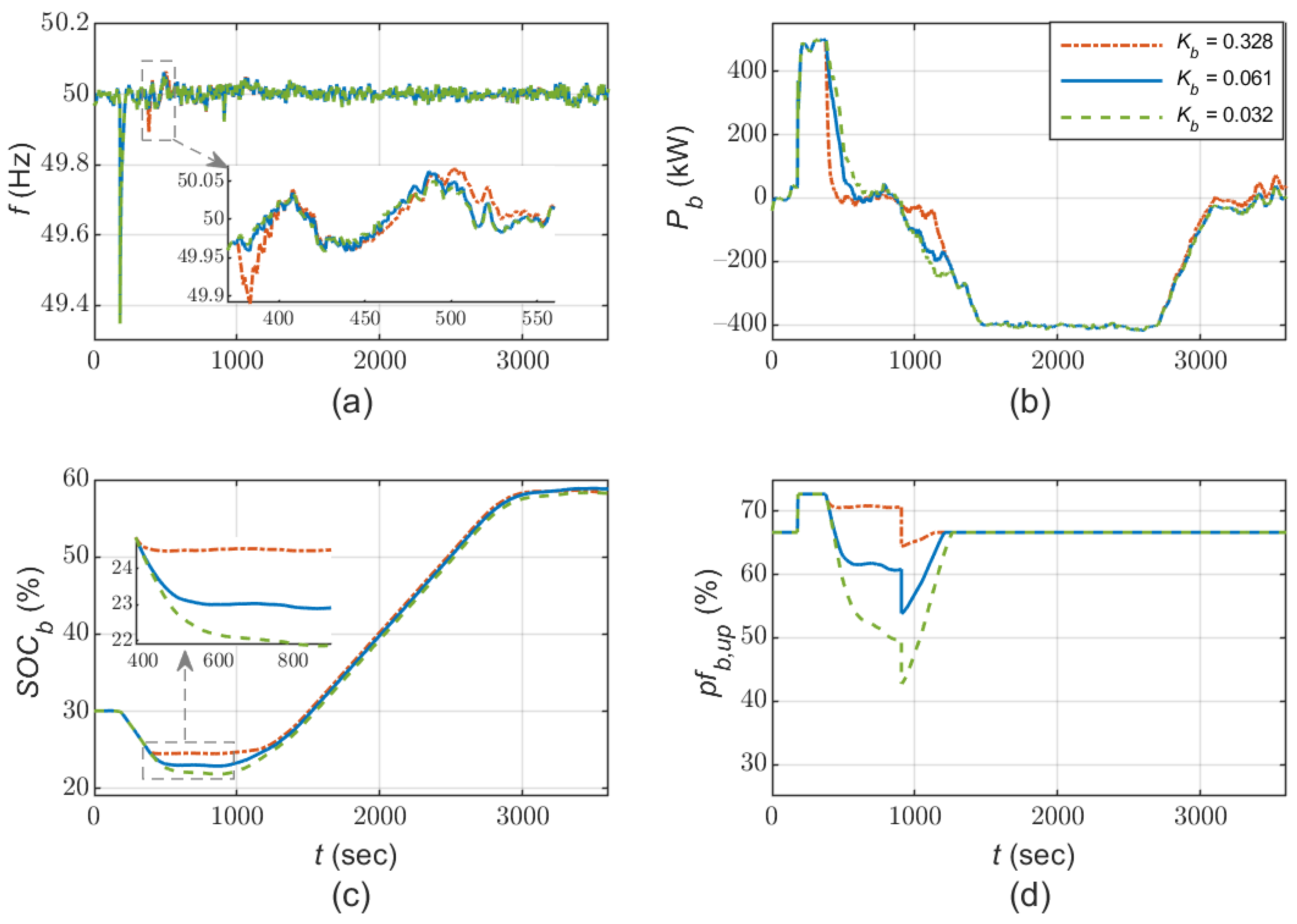
5.2.1. Kb Gain

The proportional gain Kb modulates BESS response when local SOC regulation is activated. Selecting a smaller gain will enhance the participation of the battery in aFRR provision but will also lead to operating closer to the edge of its SOC range. In Figure 11, the frequency, BESS response, SOC and participation factor are shown for three different Kb values (0.328, 0.061, 0.032), resulting from the tuning process described in Section 2.1, by requiring P b , s o c * = 1 pu for SOC 24.5% (red/dash-dotted), 22.5% (blue/continuous) and 20.5% (green/dashed), respectively.
Transition from providing secondary reserves to idling is smoother when smaller Kb values are used, thus minimizing the small transients in frequency noted in Figure 11a when entering the minimum SOC activation zone. However, a smaller Kb value leaves SOC closer to its minimum limit, even though this is never exceeded (Figure 11c). For this reason, a minor increase in BESS cycles takes place at low Kb values (cycle range: 0.40–0.45). Since smaller Kb values result in lower SOC levels in real-time operation, this also leads to reduced pfb,up values (as in Figure 11d), according to Equation (1) and the calculation of cb,up (Figure 2).
Overall, lower Kb values seem preferable, taking into account the improved exploitation of BESS energy reserves in real-time operation and the smoother transition to idling. However, higher Kb values will result in a slightly increased SOC level following a contingency, thus allowing provision of FCR to be sustained longer, if necessary. A relevant requirement is set in ENTSO-e’s proposal concerning limited-energy resources’ participation in frequency regulation [57].

5.2.2. SOC Activation Zone Range

The effect of SOC control activation zones is examined for SOCb,min+ equal to 21% (red/dash-dotted), 25% (blue/continuous) and 29% (green/dashed), while implementing the proposed control scheme. Kb is re-tuned in each case, according to the principles described in Section 2.1, so that P b , s o c * = 1 pu when SOCb = (SOCb,min− + SOCb,min+)/2. Figure 12 shows that the SOC control activation zone has a negligible effect on system frequency, with narrower zones leading to slightly higher frequency variations, due to the steeper cb,up slope. As with Kb, lower SOCb,min+ values lead to deeper battery energy reserve depletion following the disturbance. BESS cycles are 0.38, 0.43 and 0.46 for SOCb,min+ equal to 29%, 25% and 21%, respectively. For SOCb,min+ = 29%, the storage unit provides its full power reserves for only ~40 s, then reaches SOCb,min+. Overall, a narrower SOC activation zone seems preferable, as it would allow improved exploitation of available energy capacity, without any substantial impact on frequency quality. Its main drawback is a deeper discharge of the batteries.

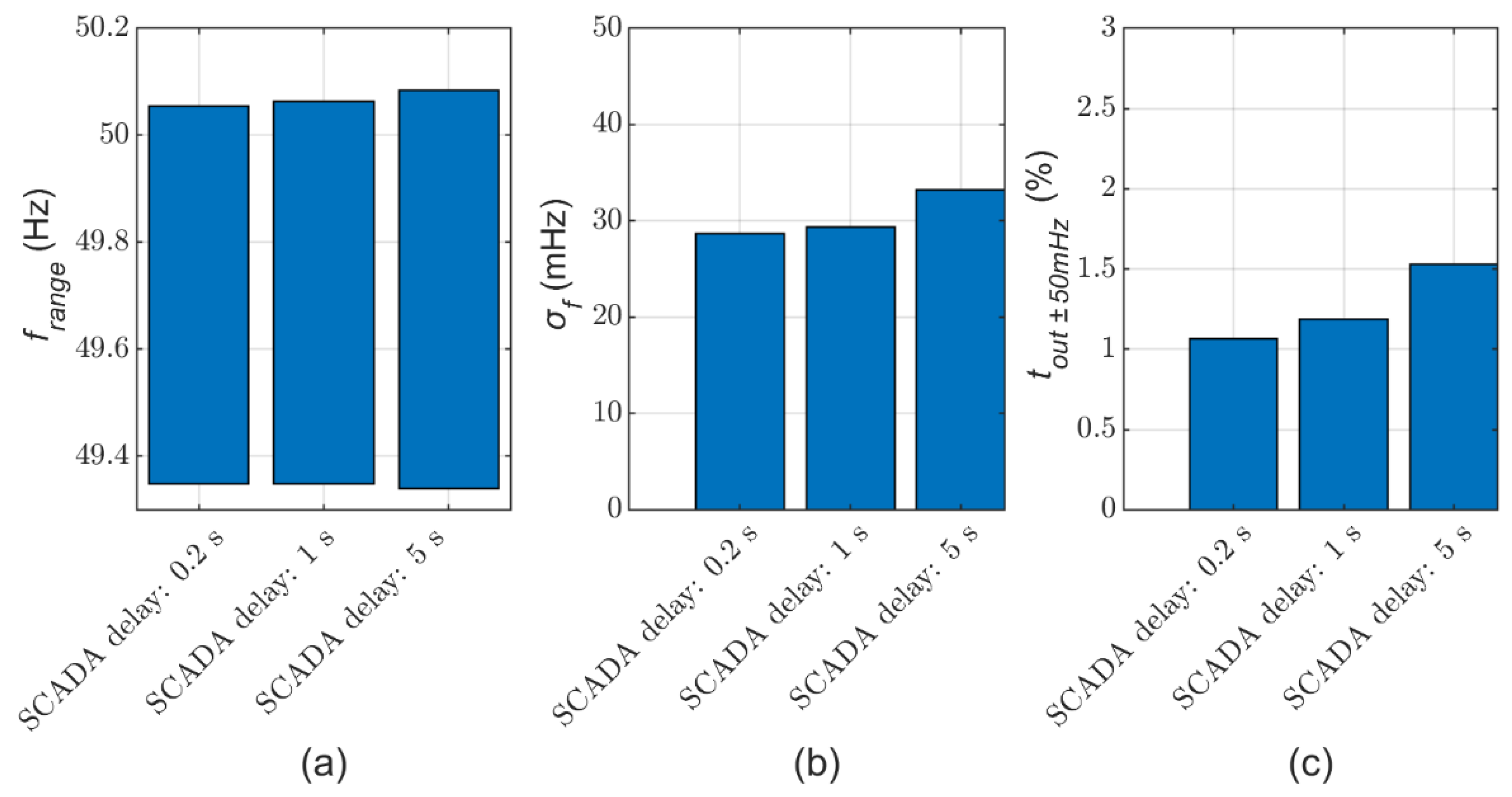
5.2.3. AGC Communication Delay

A sensitivity analysis is conducted to evaluate the dependence of the proposed method on communication efficiency by varying the SCADA time delay, so far assumed equal to 1 s in all simulations (Table A2). To demonstrate the effectiveness of the proposed method for a wide range, system frequency and BESS active power are shown in Figure 13, for three different SCADA time delay values, namely 0.2 s (red/dash-dotted line), 1 s (blue/continuous line) and 5 s (green/dashed line). The frequency quality metrics in each case are presented in Figure 14. It is observed that the effect of delays in data transfer between the battery unit and the AGC are insignificant, with the performance of the proposed method remaining effectively the same.

6. Conclusions

This paper presents a coordinated active power control scheme for a BESS participating in frequency containment and restoration, along with other regulating units. A comprehensive approach is introduced, comprising the economic dispatch schedule, AGC system and real-time local battery controller. A typical AGC, without any major deviation from systems implemented in practice, regulated deployment of secondary reserves, while BESS-level control ensures that SOC remains within acceptable limits, even following severe contingencies. For this purpose, a SOC controller is implemented locally, while BESS aFRR provision is gradually reduced when the SOC approaches its variation limits, re-dispatching aFRR from the batteries to other units under AGC control. All units are subject to economic dispatch scheduling, which is responsible for SOC restoration, via appropriate charge/discharge dispatch orders, ensuring that this process does not deplete the operating reserves of the system.
Simulation results from the application of the proposed BESS participation concept in a non-interconnected island system demonstrate its effectiveness. The batteries provide frequency restoration reserves in parallel with other regulating units, along with FCR and inertial response. When the SOC approaches its variation limits, BESS participation in LFC is gradually reduced, with secondary regulation undertaken by the other generating units in a smooth and well-coordinated manner via the central AGC system. The SOC is regulated back to its reference value when conditions allow, through a process managed by the system’s real-time economic dispatch process, rather than locally at the BESS level. In comparison to the other power control schemes evaluated in the paper, the main advantages of the proposed method lie in allowing the batteries to participate in the AGC and ED process on equal terms with other regulating units, whilst effectively managing energy reserve depletion. The robustness of the method is evaluated against various parameters. The proposed method is easily applicable in large-scale interconnected power systems and in the presence of multiple independent BESSs.
With storage taking up the role of traditional dispatchable generation in decarbonized power systems, further work on energy reserve management and prevention of depletion to ensure effective provision of balancing services is of critical importance. Future extensions of this work could include BESS portfolios’ secondary frequency regulation, RES participation in reserve provision and therefore storage charge management, adaptation of the proposed method for systems operating without conventional units, i.e., relying on RESs and storage, and expansion of the economic dispatch module to accommodate more sophisticated market functionalities.

Author Contributions

Conceptualization, A.G.P.; methodology, A.G.P.; software, A.G.P.; validation, A.G.P. and S.A.P.; writing—original draft preparation, A.G.P.; writing—review and editing, S.A.P.; visualization, A.G.P. and S.A.P.; supervision, S.A.P.; funding acquisition, A.G.P. All authors have read and agreed to the published version of the manuscript.

Funding

The work of Apostolos G. Papakonstantinou is co-financed by Greece and the European Union (European Social Fund—ESF) through the Operational Programme “Human Resources Development, Education and Lifelong Learning” in the context of the project “Strengthening Human Resources Research Potential via Doctorate Research” (MIS-5000432), implemented by the State Scholarships Foundation (ΙΚΥ).
Applsci 12 00596 i001

Conflicts of Interest

The authors declare no conflict of interest.

Appendix A. Economic Dispatch and Frequency Control Parameters

Table A1. Economic dispatch problem parameters.
ParameterSymbolValue
ED time intervalΔt0.25 h
Set of available DUsG{G1–6}
Maximum capacity of each DU P g i , m a x 1 MW
Minimum loading (technical minimum) of each DU P g i , m i n 0.5 MW
BESS maximum charge/discharge power P b , c / d , m a x 0.5 MW
BESS energy capacity E b , m a x 0.5 MWh
SOC reference S O C t b * 55%
BESS charge/discharge efficiency n b , c / d 0.92
Variable cost of each DU V C g i 100 €/MWh
SOC limit violation cost C s l , s o c 200 €/MWh
Downward reserve violation cost C d n s l , r 4000 €/MWh
Upward reserve violation cost C u p s l , r 8000 €/MWh
Energy equilibrium violation cost C s l , e q 20,000 €/MWh
Table A2. Time-domain simulation parameters.
ParameterSymbolValue
DU type S t r g i 4-stroke
DU droop coefficient R g i 5%
DU inertia constant H g i 2.5 s
DU active power rate limiter | d P g i / d t | max 0.3 pu/s
DU AGC dispatch order rate limiter | d P g i , a g c * / d t | max 0.02 pu/s
PV capacity P p v , n 1 MWp
WT capacity P w , n 0.9 MW
BESS frequency measurement dead band f b , d b 0.01 Hz
BESS droop coefficient R b 2%
BESS ROCOF measurement filter time constant T b , f , r o c o f 0.05 s
BESS ROCOF measurement dead band R O C O F b , d b 0.05 Hz/s
BESS inertia constant H b 3 s
Lower limit of minimum SOC control activation zone S O C b , min 20%
Upper limit of minimum SOC control activation zone S O C b , min + 25%
Lower limit of maximum SOC control activation zone S O C b , max 85%
Upper limit of maximum SOC control activation zone S O C b , max + 90%
Minimum SOC for BAU SOC control S O C b , min , B A U 22.5%
Maximum SOC for BAU SOC control S O C b , max , B A U 87.5%
SOC control gain K b 0.0615
BESS active power rate limiter | d P b * / d t | max 10 pu/s
BESS AGC dispatch order and SOC controller power reference rate limiter | d P b , a g c / s o c * / d t | max 0.1 pu/s
PI gains of BESS current controller ( K b , p , v s c , K b , i , v s c ) (0.1,5)
DU AGC time constant in filter-based AGC T f , a g c 60 s
PI gains of AGC ( K p , a g c , K i , a g c ) (0.005,0.05)
AGC cycle T a g c 4 s
SCADA communication delay T d , S C A D A 1 s

References

  1. European Commission. Study on Energy Storage—Contribution to the Security of the Electricity Supply in Europe; European Commission: Brussels, Belgium, 2020. [Google Scholar]
  2. Electricity Storage Valuation Framework: Assessing System Value and Ensuring Project Viability; International Renewable Energy Agency: Abu Dhabi, United Arab Emirates, 2020.
  3. Iris, Ç.; Lam, J.S.L. Optimal energy management and operations planning in seaports with smart grid while har-nessing renewable energy under uncertainty. Omega 2021, 103, 102445. [Google Scholar] [CrossRef]
  4. Hatziargyriou, N.; Margaris, I.; Stavropoulou, I.; Papathanassiou, S.; Dimeas, A. Noninterconnected Island Systems: The Greek Case. IEEE Electrif. Mag. 2017, 5, 17–27. [Google Scholar] [CrossRef]
  5. Psarros, G.N.; Papakonstantinou, A.G.; Papathanassiou, S.A. Integration of storage into large island power systems: The case of Cyprus. In Proceedings of the 12th Mediterranean Conference on Power Generation, Transmission, Distribution and Energy Conversion (MEDPOWER 2020), Paphos, Cyprus, 9–12 November 2020; Institution of Engineering and Technology (IET): London, UK, 2021; pp. 270–275. [Google Scholar]
  6. Psarros, G.N.; Karamanou, E.G.; Papathanassiou, S.A. Feasibility Analysis of Centralized Storage Facilities in Isolated Grids. IEEE Trans. Sustain. Energy 2018, 9, 1822–1832. [Google Scholar] [CrossRef]
  7. Psarros, G.N.; Kokkolios, S.P.; Papathanassiou, S.A. Centrally Managed Storage Facilities in Small Non-Interconnected Island Systems. In Proceedings of the 2018 53rd International Universities Power Engineering Conference (UPEC), Glasgow, UK, 4–7 September 2018; pp. 1–6. [Google Scholar]
  8. Psarros, G.N.; Papakonstantinou, A.G.; Papathanassiou, S.A.; Anagnostopoulos, J.S.; Boulaxis, N.G. Contribution of energy storage to capacity adequacy—Application to island power systems. In Proceedings of the 48th CIGRE Sess, Paris, France, 23–28 August 2020; pp. 1–11. [Google Scholar]
  9. Dratsas, P.A.; Psarros, G.N.; Papathanassiou, S.A. Battery Energy Storage Contribution to System Adequacy. Energies 2021, 14, 5146. [Google Scholar] [CrossRef]
  10. Meng, L.; Zafar, J.; Khadem, S.K.; Collinson, A.; Murchie, K.C.; Coffele, F.; Burt, G.M. Fast Frequency Response From Energy Storage Systems—A Review of Grid Standards, Projects and Technical Issues. IEEE Trans. Smart Grid 2019, 11, 1566–1581. [Google Scholar] [CrossRef] [Green Version]
  11. Kundur, P. Power System Stability and Control; McGraw-Hill Inc.: New York, NY, USA, 1994. [Google Scholar]
  12. Wood, A.J.; Wollenberg, B.F.; Sheble, G.B. Power Generation, Operation, and Control, 3rd ed.; John Wiley & Sons Inc.: New Jersey, NJ, USA, 2013. [Google Scholar]
  13. Lazard’s Levelized Cost of Storage Analysis—Version 7.0; Lazard: Hamilton, Bermuda, 2021; Available online: https://www.lazard.com/media/451882/lazards-levelized-cost-of-storage-version-70-vf.pdf (accessed on 4 December 2021).
  14. Stroe, D.-I.; Knap, V.; Swierczynski, M.J.; Stroe, A.-I.; Teodorescu, R. Operation of a Grid-Connected Lithium-Ion Battery Energy Storage System for Primary Frequency Regulation: A Battery Lifetime Perspective. IEEE Trans. Ind. Appl. 2017, 53, 430–438. [Google Scholar] [CrossRef]
  15. Aznavi, S.; Fajri, P.; Sabzehgarm, R.; Asrari, A. Optimal management of residential energy storage systems in presence of intermittencies. J. Build. Eng. 2020, 29, 101149. [Google Scholar] [CrossRef]
  16. Hartmann, B.; Divényi, D.; Vokony, I. Evaluation of business possibilities of energy storage at commercial and industrial consumers—A case study. Appl. Energy 2018, 222, 59–66. [Google Scholar] [CrossRef]
  17. Del Granado, P.C.; Pang, Z.; Wallace, S.W. Synergy of smart grids and hybrid distributed generation on the value of energy storage. Appl. Energy 2016, 170, 476–488. [Google Scholar] [CrossRef] [Green Version]
  18. Iris, Ç.; Lam, J.S.L. A review of energy efficiency in ports: Operational strategies, technologies and energy management systems. Renew. Sustain. Energy Rev. 2019, 112, 170–182. [Google Scholar] [CrossRef]
  19. Moura, S.J.; Callaway, D.S.; Fathy, H.K.; Stein, J.L. Tradeoffs between battery energy capacity and stochastic optimal power management in plug-in hybrid electric vehicles. J. Power Sources 2010, 195, 2979–2988. [Google Scholar] [CrossRef]
  20. Margaris, I.D.; Papathanassiou, S.A.; Hatziargyriou, N.D.; Hansen, A.D.; Sørensen, P.E. Frequency Control in Autonomous Power Systems With High Wind Power Penetration. IEEE Trans. Sustain. Energy 2012, 3, 189–199. [Google Scholar] [CrossRef]
  21. Papaefthymiou, S.V.; Lakiotis, V.G.; Margaris, I.D.; Papathanassiou, S.A. Dynamic analysis of island systems with wind-pumped-storage hybrid power stations. Renew. Energy 2015, 74, 544–554. [Google Scholar] [CrossRef]
  22. Nanou, S.I.; Papakonstantinou, A.G.; Papathanassiou, S.A. A generic model of two-stage grid-connected PV systems with primary frequency response and inertia emulation. Electr. Power Syst. Res. 2015, 127, 186–196. [Google Scholar] [CrossRef]
  23. Bevrani, H.; Golpîra, H.; Messina, A.R.; Hatziargyriou, N.; Milano, F.; Ise, T. Power system frequency control: An updated review of current solutions and new challenges. Electr. Power Syst. Res. 2021, 194, 107114. [Google Scholar] [CrossRef]
  24. Karapanos, V.; Kotsampopoulos, P.; Hatziargyriou, N. Performance of the linear and binary algorithm of virtual synchronous generators for the emulation of rotational inertia. Electr. Power Syst. Res. 2015, 123, 119–127. [Google Scholar] [CrossRef]
  25. Serban, I.; Marinescu, C. Control Strategy of Three-Phase Battery Energy Storage Systems for Frequency Support in Microgrids and with Uninterrupted Supply of Local Loads. IEEE Trans. Power Electron. 2013, 29, 5010–5020. [Google Scholar] [CrossRef]
  26. Liu, H.; Hu, Z.; Song, Y.; Lin, J. Decentralized Vehicle-to-Grid Control for Primary Frequency Regulation Considering Charging Demands. IEEE Trans. Power Syst. 2013, 28, 3480–3489. [Google Scholar] [CrossRef]
  27. Akram, U.; Khalid, M.; Shafiq, S. A Novel Operation Strategy of Battery-Supercapacitor Hybrid Energy Storage System Providing Frequency Regulation Service. In Proceedings of the 2018 IEEE 27th International Symposium on Industrial Electronics (ISIE), Cairns, QLD, Australia, 13–15 June 2018; pp. 31–36. [Google Scholar]
  28. Xu, X.; Bishop, M.; Oikarinen, D.G.; Hao, C. Application and modeling of battery energy storage in power systems. CSEE J. Power Energy Syst. 2016, 2, 82–90. [Google Scholar] [CrossRef]
  29. Greenwood, D.; Lim, K.; Patsios, C.; Lyons, P.; Lim, Y.; Taylor, P. Frequency response services designed for energy storage. Appl. Energy 2017, 203, 115–127. [Google Scholar] [CrossRef]
  30. Tan, Z.; Li, X.; He, L.; Li, Y.; Huang, J. Primary frequency control with BESS considering adaptive SoC recovery. Int. J. Electr. Power Energy Syst. 2020, 117, 105588. [Google Scholar] [CrossRef]
  31. Boyle, J.; Littler, T.; Foley, A. Battery energy storage system state-of-charge management to ensure availability of frequency regulating services from wind farms. Renew. Energy 2020, 160, 1119–1135. [Google Scholar] [CrossRef]
  32. Commission Regulation (EU) 2017/2195 of 23 November 2017 establishing a guideline on electricity balancing. Off. J. Eur. Union 2017, 312, 6–53.
  33. Brouwer, A.S.; van den Broek, M.; Seebregts, A.; Faaij, A. Impacts of large-scale Intermittent Renewable Energy Sources on electricity systems, and how these can be modeled. Renew. Sustain. Energy Rev. 2014, 33, 443–466. [Google Scholar] [CrossRef]
  34. Supporting Document for the Network Code on Load-Frequency Control and Reserves; European Network of Transmission System Operators for Electricity (ENTSO-E): Brussels, Belgium, 2013.
  35. Zhang, F.; Hu, Z.; Xie, X.; Zhang, J.; Song, Y. Assessment of the Effectiveness of Energy Storage Resources in the Frequency Regulation of a Single-Area Power System. IEEE Trans. Power Syst. 2017, 32, 3373–3380. [Google Scholar] [CrossRef]
  36. Amano, H.; Ohshiro, Y.; Kawakami, T.; Inoue, T. Utilization of battery energy storage system for load frequency control toward large-scale renewable energy penetration. In Proceedings of the 2012 3rd IEEE PES Innovative Smart Grid Technologies Europe (ISGT Europe), Berlin, Germany, 14–17 October 2012; pp. 1–7. [Google Scholar]
  37. Kim, Y.-J. Experimental study of battery energy storage systems participating in grid frequency regulation. In Proceedings of the 2016 IEEE/PES Transmission and Distribution Conference and Exposition (T&D), Dallas, TX, USA, 3–5 May 2016; pp. 1–5. [Google Scholar]
  38. Song, J.; Pan, X.; Lu, C.; Xu, H. A Simulation-Based Optimization Method for Hybrid Frequency Regulation System Configuration. Energies 2017, 10, 1302. [Google Scholar] [CrossRef] [Green Version]
  39. Zhang, S.; Liu, H.; Wang, F.; Yan, T.; Wang, K. Secondary frequency control strategy for BESS considering their degree of participation. Energy Rep. 2020, 6, 594–602. [Google Scholar] [CrossRef]
  40. Cheng, Y.; Tabrizi, M.; Sahni, M.; Povedano, A.; Nichols, D. Dynamic Available AGC Based Approach for Enhancing Utility Scale Energy Storage Performance. IEEE Trans. Smart Grid 2014, 5, 1070–1078. [Google Scholar] [CrossRef]
  41. Doenges, K.; Egido, I.; Sigrist, L.; Miguelez, E.L.; Rouco, L. Improving AGC Performance in Power Systems With Regulation Response Accuracy Margins Using Battery Energy Storage System (BESS). IEEE Trans. Power Syst. 2019, 35, 2816–2825. [Google Scholar] [CrossRef]
  42. Datta, U.; Kalam, A.; Shi, J. Battery Energy Storage System Control for Mitigating PV Penetration Impact on Primary Frequency Control and State-of-Charge Recovery. IEEE Trans. Sustain. Energy 2020, 11, 746–757. [Google Scholar] [CrossRef] [Green Version]
  43. Orihara, D.; Saitoh, H. Battery-assisted load frequency control coordinated with economic load dispatching. In Proceedings of the 2017 IEEE Innovative Smart Grid Technologies—Asia (ISGT-Asia), Auckland, New Zealand, 4–7 December 2017; pp. 1–5. [Google Scholar]
  44. Liang, L.; Zhong, J.; Jiao, Z. Frequency regulation for a power system with wind power and battery energy storage. In Proceedings of the IEEE International Conference on Power System Technology (POWERCON), Auckland, New Zealand, 30 October–2 November 2012; pp. 1–6. [Google Scholar]
  45. Aditya, S.; Das, D. Battery energy storage for load frequency control of an interconnected power system. Electr. Power Syst. Res. 2001, 58, 179–185. [Google Scholar] [CrossRef]
  46. Borsche, T.; Ulbig, A.; Koller, M.; Andersson, G. Power and energy capacity requirements of storages providing frequency control reserves. In Proceedings of the 2013 IEEE Power & Energy Society General Meeting, Vancouver, BC, Canada, 21–25 July 2013; pp. 1–5. [Google Scholar]
  47. Koller, M.; Borsche, T.; Ulbig, A.; Andersson, G. Review of grid applications with the Zurich 1MW battery energy storage system. Electr. Power Syst. Res. 2015, 120, 128–135. [Google Scholar] [CrossRef]
  48. Chang, J.-W.; Lee, G.-S.; Moon, H.-J.; Glick, M.B.; Moon, S.-I. Coordinated Frequency and State-of-Charge Control with Multi-Battery Energy Storage Systems and Diesel Generators in an Isolated Microgrid. Energies 2019, 12, 1614. [Google Scholar] [CrossRef] [Green Version]
  49. Kim, Y.-S.; Kim, E.-S.; Moon, S.-I. Frequency and Voltage Control Strategy of Standalone Microgrids with High Penetration of Intermittent Renewable Generation Systems. IEEE Trans. Power Syst. 2016, 31, 718–728. [Google Scholar] [CrossRef]
  50. Datta, M.; Senjyu, T. Fuzzy Control of Distributed PV Inverters/Energy Storage Systems/Electric Vehicles for Frequency Regulation in a Large Power System. IEEE Trans. Smart Grid 2013, 4, 479–488. [Google Scholar] [CrossRef]
  51. Tan, J.; Zhang, Y. Coordinated Control Strategy of a Battery Energy Storage System to Support a Wind Power Plant Providing Multi-Timescale Frequency Ancillary Services. IEEE Trans. Sustain. Energy 2017, 8, 1140–1153. [Google Scholar] [CrossRef]
  52. Li, P.; Tan, Z.; Zhou, Y.; Li, C.; Li, R.; Qi, X. Secondary Frequency Regulation Strategy With Fuzzy Logic Method and Self-Adaptive Modification of State of Charge. IEEE Access 2018, 6, 43575–43585. [Google Scholar] [CrossRef]
  53. Hosseinzadeh, M.; Salmasi, F.R. Power management of an isolated hybrid AC/DC micro-grid with fuzzy control of battery banks. IET Renew. Power Gener. 2015, 9, 484–493. [Google Scholar] [CrossRef]
  54. Zhu, D.; Hug-Glanzmann, G. Robust control design for integration of energy storage into frequency regulation. In Proceedings of the 2012 3rd IEEE PES Innovative Smart Grid Technologies Europe (ISGT Europe), Berlin, Germany, 14–17 October 2012; pp. 1–8. [Google Scholar]
  55. Bevrani, H.; Hiyama, T. Intelligent Automatic Generation Control; CRC Press: Boca Raton, FL, USA, 2011. [Google Scholar]
  56. Koller, M.; Borsche, T.; Ulbig, A.; Andersson, G. Defining a degradation cost function for optimal control of a battery energy storage system. In Proceedings of the 2013 IEEE Grenoble Conference, Grenoble, France, 16–20 June 2013; pp. 1–6. [Google Scholar]
  57. All CE TSOs’ Proposal for Additional Properties of FCR in Accordance with Article 154(2) of the Commission Regulation (EU) 2017/1485 of 2 August 2017 Establishing a Guideline on Electricity Transmission System Operation; ENTSO-e: Brussels, Belgium, 2019.
  58. Cyprus Transmission and Distribution Rules 5.3.0; Transmission System Operator: Strovolos, Cyprus, 2020. (In Greek)
  59. Yazdani, A.; Iravani, R. Voltage-Sourced Converters in Power Systems; Wiley-VCH Verlag GmbH: New York, NY, USA, 2010. [Google Scholar]
  60. Psarros, G.; Nanou, S.; Papaefthymiou, S.V.; Papathanassiou, S.A. Generation scheduling in non-interconnected islands with high RES penetration. Renew. Energy 2018, 115, 338–352. [Google Scholar] [CrossRef]
  61. Amano, H.; Shima, W.; Kawakami, T.; Inoue, T.; Uehara, Y.; Nakama, H.; Oshiro, Y.; Toguchi, M. Field verification of control performance of a LFC system to make effective use of existing power generation and battery energy storage system. In Proceedings of the IEEE PES ISGT Europe 2013, Lyngby, Denmark, 6–9 October 2013; pp. 1–5. [Google Scholar]
  62. Dai, J.; Castro, H.; Guo, J.; Khandelwal, T.; Shokooh, S.; Shokooh, F. Automatic generation control system for an industrial facility with onsite generation. In Proceedings of the 2009 IEEE/PES Power Systems Conference and Exposition, Seattle, WA, USA, 15–18 March 2009; pp. 1–8. [Google Scholar]
  63. Roy, S.; Malik, O.; Hope, G. Adaptive control of speed and equivalence ratio dynamics of a diesel driven power-plant. IEEE Trans. Energy Convers. 1993, 8, 13–19. [Google Scholar] [CrossRef]
  64. Turbine-Governor Models, Standard Dynamic Turbine-Governor Systems in NEPLAN Power System Analysis Tool; NEPLAN: Küsnacht, Switzerland, 2013.
  65. PSS/E Model Libray; Siemens Industry, Inc.: Munich, Germany, 2013.
  66. Tremblay, O.; Dessaint, L.-A. Experimental Validation of a Battery Dynamic Model for EV Applications. World Electr. Veh. J. 2009, 3, 289–298. [Google Scholar] [CrossRef] [Green Version]
  67. Erlich, I.; Wilch, M. Primary frequency control by wind turbines. In Proceedings of the IEEE PES General Meeting, Minneapolis, MN, USA, 25–29 July 2010; pp. 1–8. [Google Scholar]
  68. Mousa, H.H.; Youssef, A.-R.; Mohamed, E.E. State of the art perturb and observe MPPT algorithms based wind energy conversion systems: A technology review. Int. J. Electr. Power Energy Syst. 2021, 126, 106598. [Google Scholar] [CrossRef]
  69. Wu, Z.; Gao, W.; Wang, J.; Gu, S. A coordinated primary frequency regulation from Permanent Magnet Synchronous Wind Turbine Generation. In Proceedings of the 2012 IEEE in Power Electronics and Machines in Wind Applications (PEMWA), Denver, CO, USA, 16–18 July 2012; pp. 1–6. [Google Scholar] [CrossRef]
  70. Malatestas, P.; Papadopoulos, M.; Stavrakakis, G. Modeling and identification of diesel-wind turbines systems for wind penetration assessment. IEEE Trans. Power Syst. 1993, 8, 1091–1097. [Google Scholar] [CrossRef]
  71. Bründlinger, R.; Schaupp, T.; Arnold, G.; Schäfer, N.; Graditi, G.; Adinolfi, G. Implementation of the European Network Code on Requirements for Generators on the European National Level. In Proceedings of the 8th Sol Integr Work, Stockholm, Sweden, 13–14 July 2018. [Google Scholar]
  72. Non-Interconnected Island Power Systems (NIIs) Management Code; Hellenic Electricity Distribution System Operator: Athens, Greece, 2020. (In Greek)
Figure 1. Proposed active power and frequency control scheme implemented locally (battery energy storage system-BESS) and centrally (automatic generation control-AGC).
Applsci 12 00596 g001
Figure 2. Calculation of cbi,up and cbi,dn parameters.
Applsci 12 00596 g002
Figure 3. BESS converter controller.
Applsci 12 00596 g003
Figure 4. Filter-based AGC method.
Applsci 12 00596 g004
Figure 5. BAU state of charge (SOC) control scheme.
Applsci 12 00596 g005
Figure 6. Study case autonomous system.
Applsci 12 00596 g006
Figure 7. (a) Wind speed, (b) solar irradiation and (c) residual load (load-renewable energy source generation) during the 1 h simulation interval.
Applsci 12 00596 g007
Figure 8. Response following a diesel unit outage at 150 s and synchronization of another unit at 900 s, for the different regulation methods of cases (i)–(iv). (a) Frequency, (b) BESS active output power (positive: injection, negative: absorption), (c) diesel units’ (DUs) aggregate active power, (d) SOC, (e) DUs’ automatic frequency restoration reserve (aFRR)-up participation factor, (f) BESS aFRR-up participation factor.
Applsci 12 00596 g008
Figure 9. Frequency quality metrics, for cases (i)–(iv). (a) Frequency range, (b) frequency standard deviation, (c) time outside 49.95–50.05 Hz.
Applsci 12 00596 g009
Figure 10. Economic dispatch results, for cases (i)–(iv). (a) Filter-based AGC, (b) BAU, (c) no AGC feedback, (d) proposed method.
Applsci 12 00596 g010
Figure 11. Response following a diesel unit outage at 150 s and synchronization of another at 900 s, for different Kb values. (a) Frequency, (b) BESS active output power (positive: injection, negative: absorption), (c) SOC, (d) BESS aFRR-up participation factor.
Applsci 12 00596 g011
Figure 12. Response following a diesel unit outage at 150 s and synchronization of another at 900 s, for different SOC activation zones. (a) Frequency, (b) BESS active output power (positive: injection, negative: absorption), (c) SOC, (d) BESS aFRR-up participation factor.
Applsci 12 00596 g012
Figure 13. Response following a diesel unit outage at 150 s and synchronization of another at 900 s, for different supervisory control and data acquisition (SCADA) communication delays. (a) Frequency, (b) BESS active output power (positive: injection, negative: absorption).
Applsci 12 00596 g013
Figure 14. Frequency quality metrics, for different SCADA communication delays. (a) Frequency range, (b) frequency standard deviation, (c) time outside 49.95–50.05 Hz.
Applsci 12 00596 g014
Table 1. Allocation of system reserves (in kW) to DUs and BESS.
Reserves g i G ( F C R u p , t g i ) F C R u p , t b g i G a F R R u p , t g i a F R R u p , t b g i G a F R R d n , t g i a F R R d n , t b
Case (i)60030030005500
Cases (ii)–(iv)60030010020050 (0–15 min)
450 (15–60 min)
500 (0–15 min)
100 (15–60 min)
Publisher’s Note: MDPI stays neutral with regard to jurisdictional claims in published maps and institutional affiliations.

