
Large Deformation Characteristics of Surrounding Rock and Support Technology of Shallow-Buried Soft Rock Roadway: A Case Study


Abstract
:1. Introduction
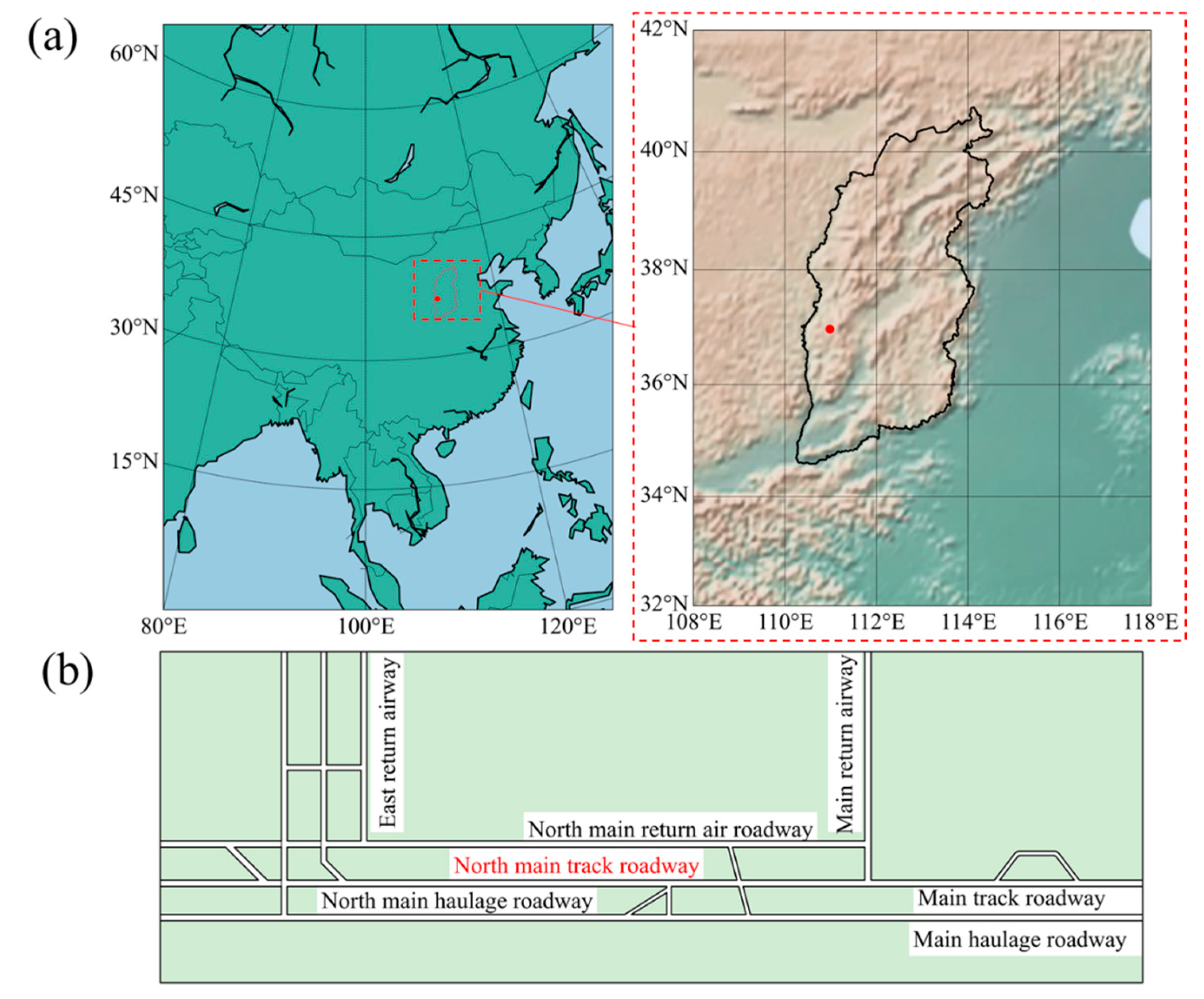
2. Project Overview
3. Field Investigation and Laboratory Tests
3.1. Damage of the Surrounding Rock Surface
3.2. Development of Deep Fracture in the Surrounding Rock
3.3. Laboratory Tests
4. Numerical Calculations
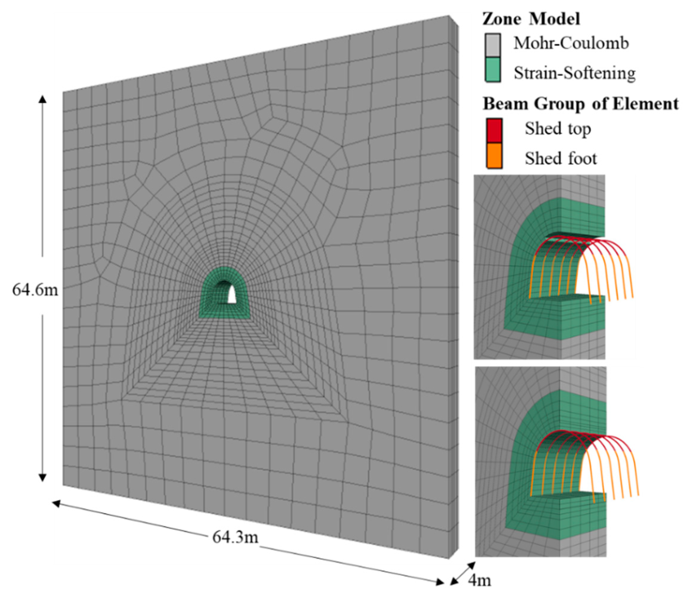
4.1. Model Establishment
4.2. The Constitutive Model and Parameter Calibration
4.3. Results
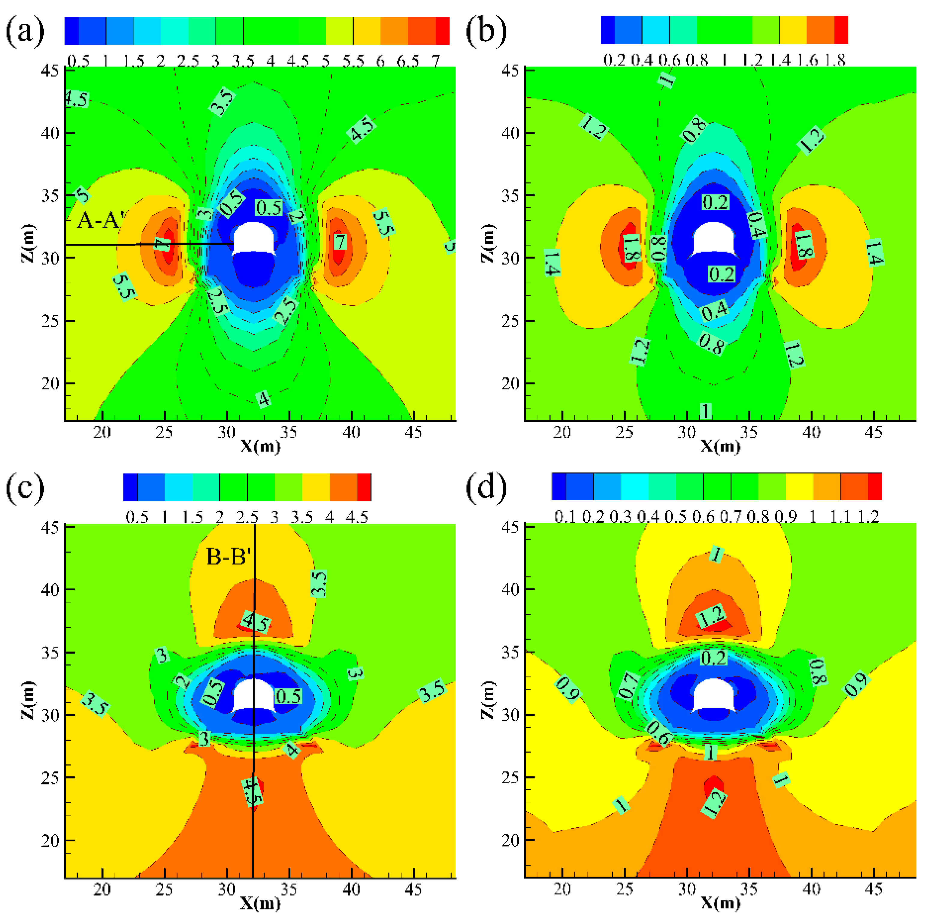
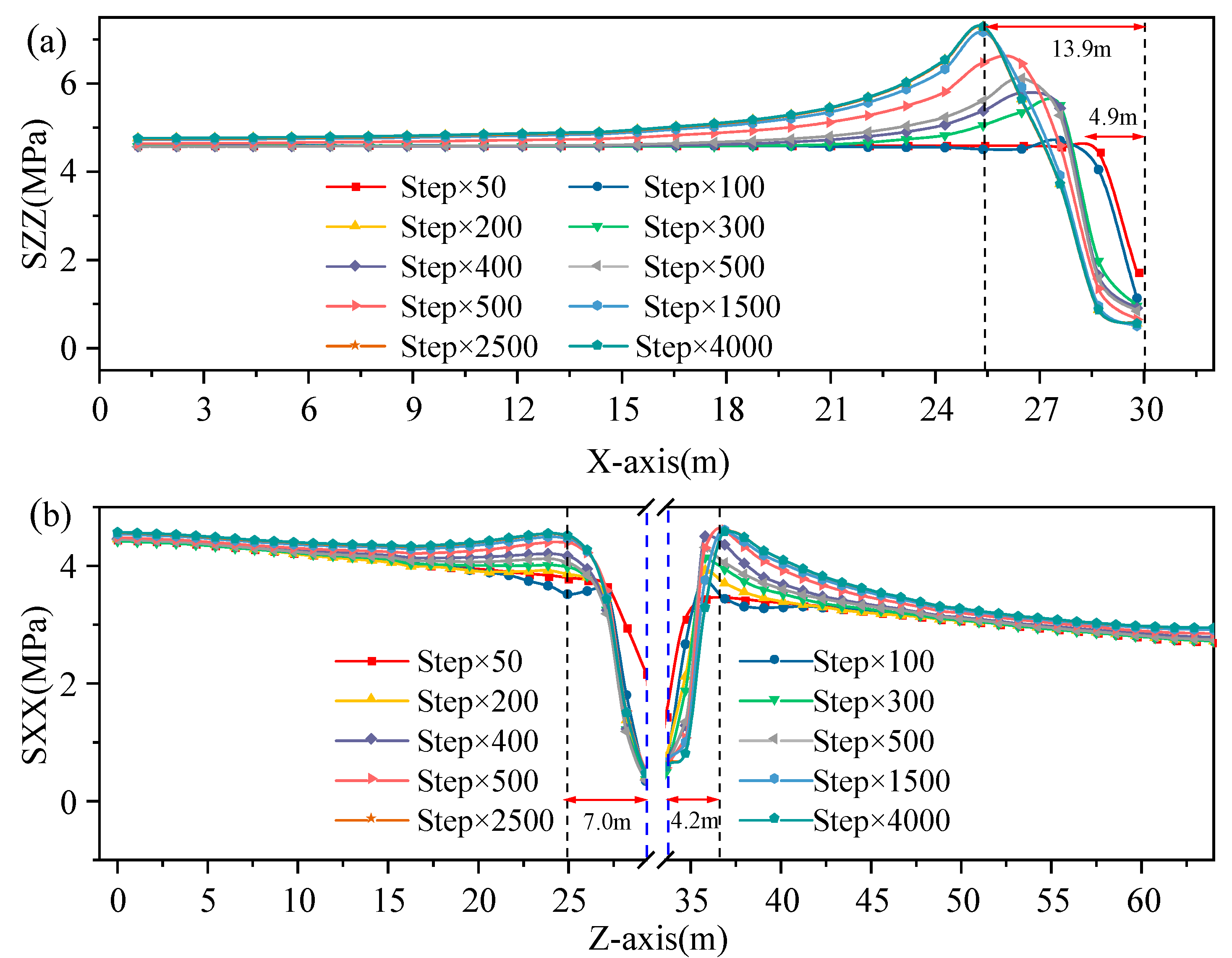
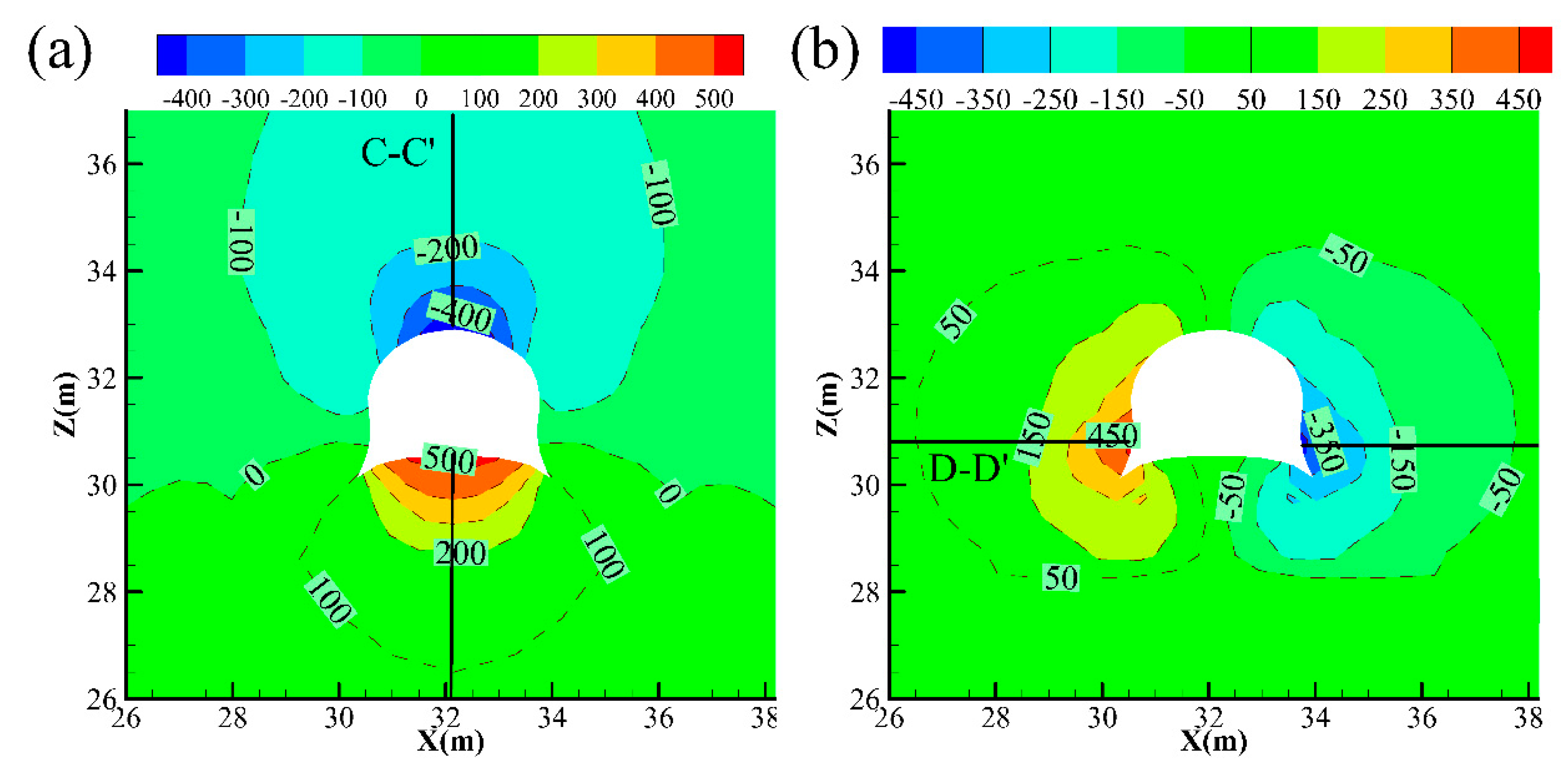
4.3.1. Stress Distribution of the Surrounding Rock
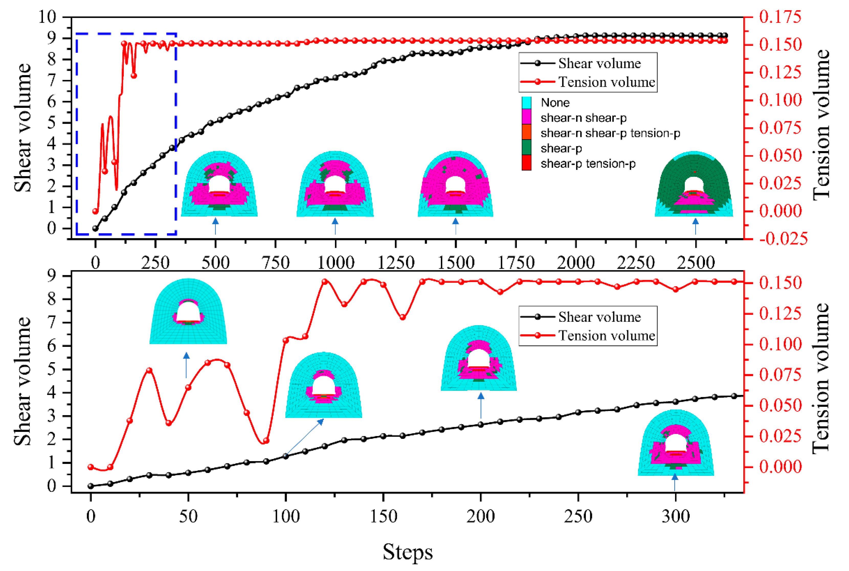
4.3.2. Plasticity State of the Surrounding Rock
4.3.3. Deformation of the Surrounding Rock
4.3.4. Failure Characteristics of the Supporting Structure
5. Stability Control Scheme of the Surrounding Rock
5.1. Influencing Factor for the Deformation of the Surrounding Rock
- (1)
- Influence of the surrounding rock lithology: The coal and rock masses exposed during roadway excavation are all soft rocks with poor strength, stability, and self-supporting ability; this mainly facilitates roadway deformation failure. Additionally, owing to the different degrees of water spraying in the roadway, the surrounding rock variably absorbs water and swells to become muddy, which further deteriorates it.
- (2)
- Influence of the supporting structure: On the one hand, the strength of U25 steel straight wall arched supports arranged at a distance of 800 mm was not sufficient to effectively limit the deformation of the roadway, which increased the uneven deformation of the roof and the roadway sides; on the other hand, the U-shaped steel support was not in complete contact with the wooden board filling and the surrounding rock, forming point-line contact, and making it easy to bear the hollow load, so the supporting capacity could not be fully utilized.
- (3)
- Influence of the roadway location: The studied roadway is a typical shallow-buried soft rock roadway. The excavation formed a falling arch, and stress was highly concentrated at the roadway sides. Unreasonable support led to a concentration of stresses in the surrounding rocks of the roadway sides, resulting in the expansion of the roof collapse to form a collapsed arch, and the rock load in the collapsed arch continued to be affected by the supporting system.
5.2. Control Scheme of the Surrounding Rock
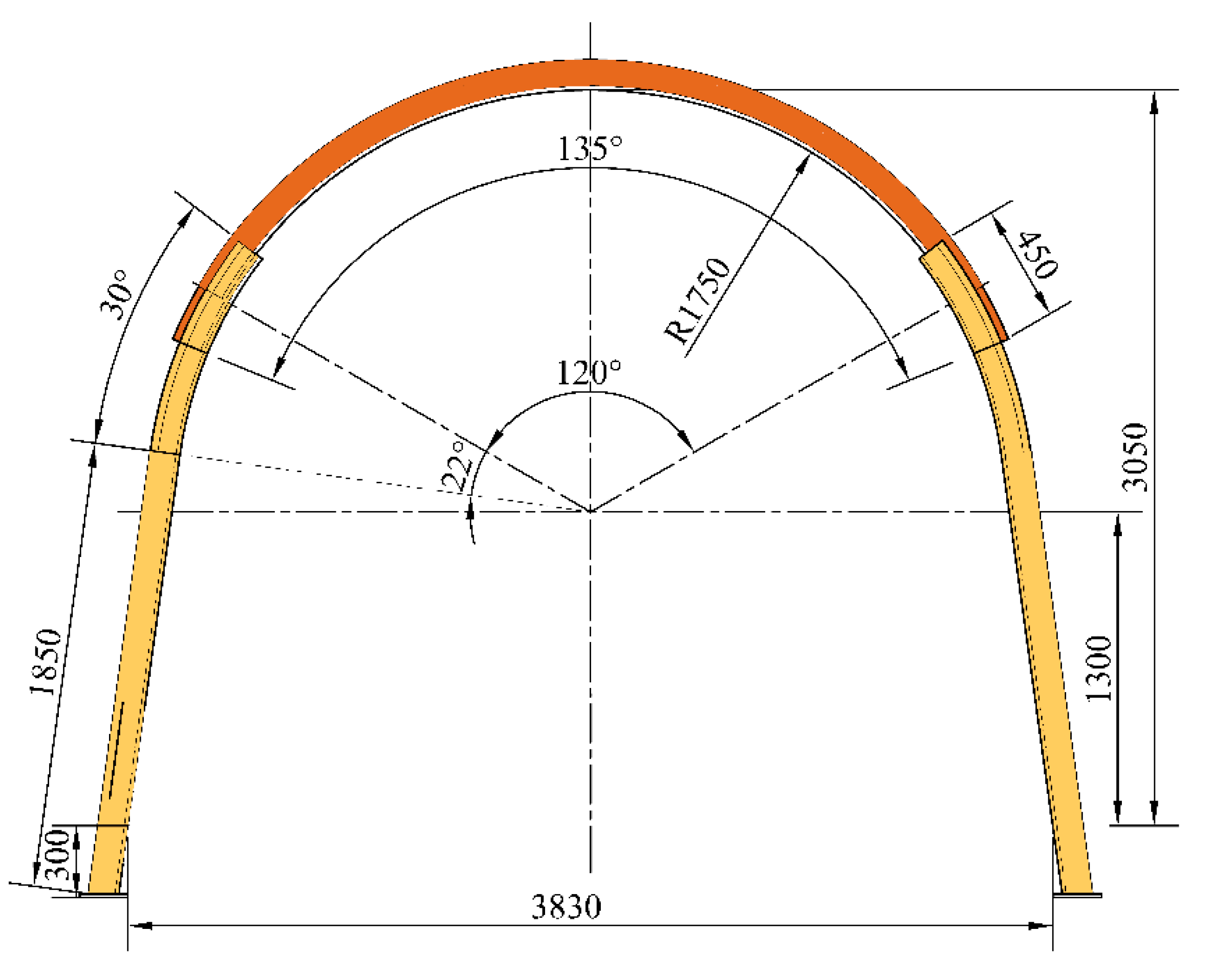
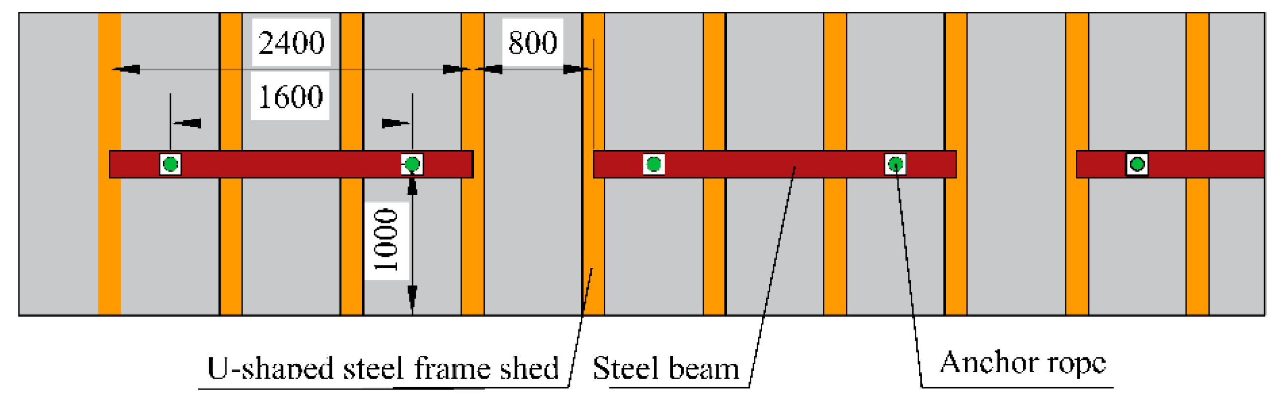
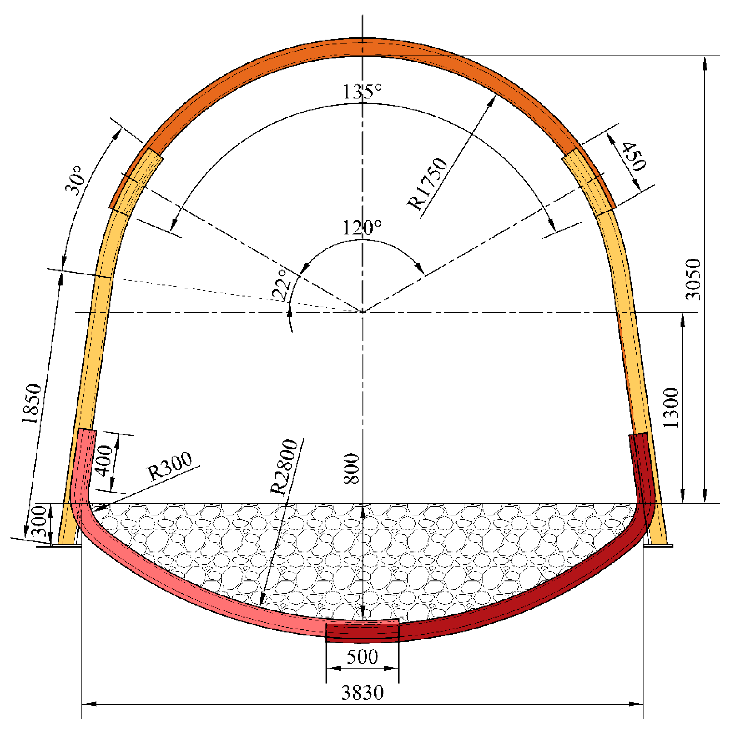
5.2.1. The Typical Support Scheme
5.2.2. Support Scheme for the Area with Severe Floor Dilation
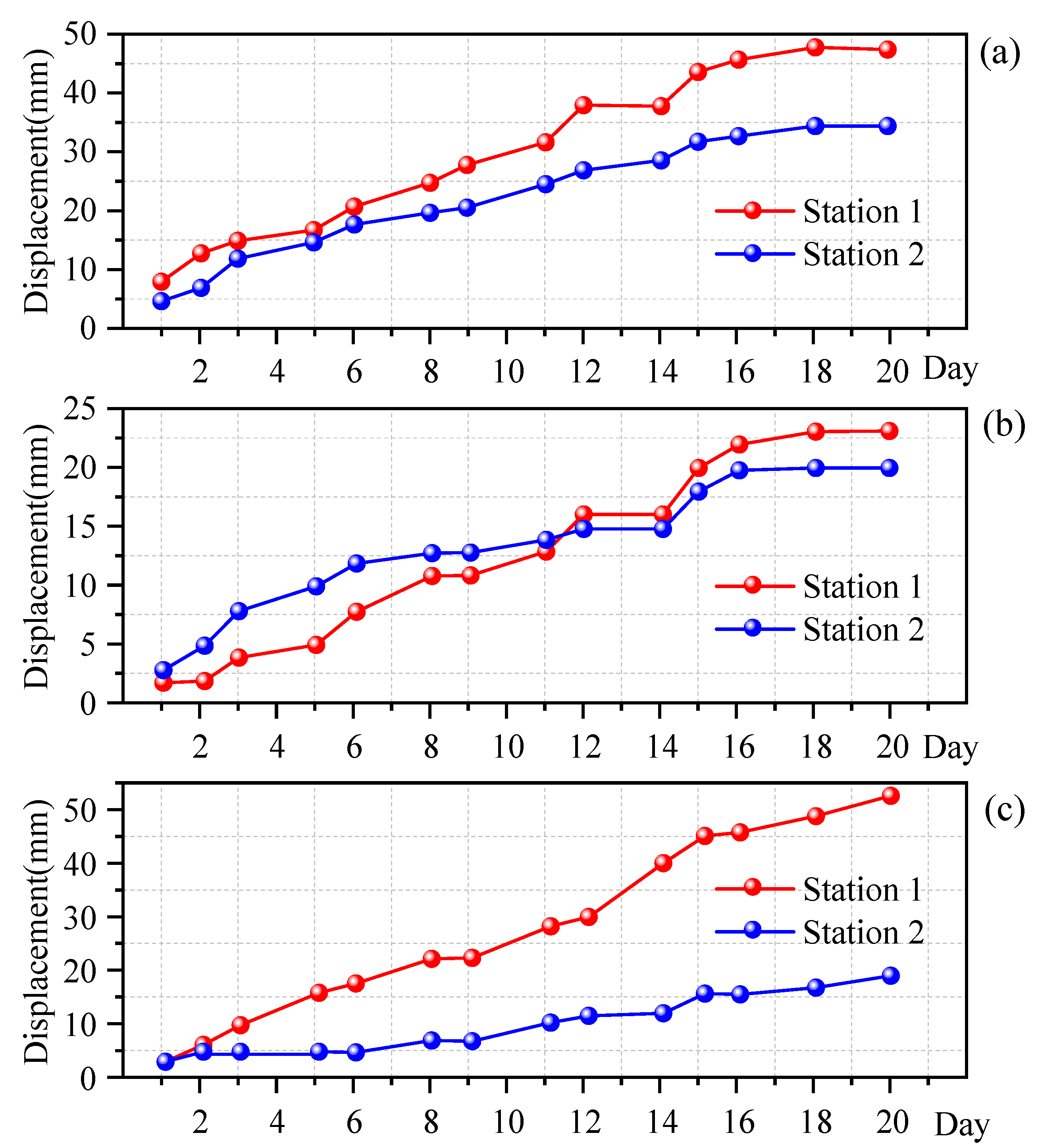
5.3. Monitoring the Displacement of the Roadway Surface
6. Conclusions
- (1)
- Field investigations and roof borehole television results showed that the roof and floor of the north return air track roadway are mainly composed of two types of mudstones, yellow mudstone and sandy mudstone. The rock layer on the surface of the roadway was loose and broken, and the deeper part of the mudstone strata had experienced cementation. The average compressive strength of the mudstone was 15.49 MPa, the average tensile strength was 0.72 MPa and the average shear strength was 3.13 MPa, which is typical of a shallow-buried soft rock roadway.
- (2)
- Numerical calculations showed that the vertical stress concentrated at both sides of the tunnel, with a stress concentration factor of 1.8 and a depth of 13.9 m. A horizontal stress concentration zone with a factor of 1.2 was formed at 7.0 m at the top and 4.2 m at the bottom, with shear damage dominating the surrounding rock and tension damage occurring at the bottom of the tunnel. After excavation, the deformation rate of the floor was maximum, followed by that of the top slab deformation. The lack of bearing capacity of the U-shape steel caused significant deformation of the surrounding rock, and the lack of filling behind the shed caused the U-shape steel shed roof to break down. Failure of the support system caused further deformation of the surrounding rock, especially the floor drum deformation of the roadway.
- (3)
- The trackway was deformed and damaged due to the low strength of the surrounding rock, insufficient strength of the U-shaped steel shed support, and lack of correlation between the U-shaped steel shed and the inability to form a complete unit. The choice of the filling body behind the shed was unreasonable. Therefore, the surrounding rock was controlled by improving the support strength of the roadway, filling the U-shaped steel shed with slurry, increasing the association between the U-shaped steel shed, and preventing the surrounding rock from weathering by spraying slurry on the surface of the roadway. The specific plan was to use the outward sloping form of a straight wall arch retractable bracket of the U29 column leg, with a double-slotted clamp plate upper and lower limit cable. The walls were filled with grout and reinforced with a high-strength steel mesh. A U29 steel counter-arch beam was used to reinforce the floor to control its deformation. Field monitoring showed that this solution could effectively control the deformation of the surrounding rock.
Author Contributions
Funding
Conflicts of Interest
References
- Kang, H.P.; Lin, J.; Fan, M.J. Investigation on support pattern of a coal mine roadway within soft rocks—A case study. Int. J. Coal Geol. 2015, 140, 31–40. [Google Scholar] [CrossRef]
- Mcnally, G.H.; Branagan, D.F. Geotechnical consequences of the Newcastle Coal Measures rocks. Aust. J. Earth Sci. 2014, 61, 363–374. [Google Scholar] [CrossRef]
- Shen, B. Coal Mine Roadway Stability in Soft Rock: A Case Study. Rock Mech. Rock Eng. 2014, 47, 2225–2238. [Google Scholar] [CrossRef]
- Tolooiyan, A.; Dyson, A.P.; Karami, M.; Shaghaghi, T.; Ghadrdan, M. Application of Ground Penetrating Radar (GPR) to Detect Joints in Organic Soft Rock. Geotech. Test. J. 2019, 42, 257–274. [Google Scholar] [CrossRef]
- Hao, J.; Li, X.; Song, Y.; Zhang, P.; Liu, H. Analysis of mining roadway with large deformation of broken soft coal and research on supporting technology: A case study in Xin’an coal mine, China. Eng. Fail. Anal. 2021, 130, 105761. [Google Scholar] [CrossRef]
- Zhao, Q.; Zhang, N.; Peng, R.; Ll, G.; Han, C.; Guo, Y. Discrete Element Simulation of Roadway Stability in an Efflorescent Oxidation Zone. Adv. Civ. Eng. 2018, 2018, 4183748. [Google Scholar] [CrossRef]
- Jiang, B.; Wang, L.; Lu, Y.; Gu, S.; Sun, X. Failure Mechanism Analysis and Support Design for Deep Composite Soft Rock Roadway: A Case Study of the Yangcheng Coal Mine in China. Shock Vib. 2015, 2015, 452479. [Google Scholar] [CrossRef]
- Wang, D.; Jiang, Y.; Sun, X.; Luan, H.; Zhang, H. Nonlinear Large Deformation Mechanism and Stability Control of Deep Soft Rock Roadway: A Case Study in China. Sustainability 2019, 11, 6243. [Google Scholar] [CrossRef] [Green Version]
- Sun, Y.; Li, G.; Zhang, J.; Xu, J. Failure Mechanisms of Rheological Coal Roadway. Sustainability 2020, 12, 2885. [Google Scholar] [CrossRef] [Green Version]
- Huang, Q.; Wang, X.; Chen, X.; Qin, D.; Chang, Z. Evolution of Interior and Exterior Bearing Structures of the Deep-Soft-Rock Roadway: From Theory to Field Test in the Pingdingshan Mining Area. Energies 2020, 13, 4357. [Google Scholar] [CrossRef]
- Li, W.; Liu, J.; Chen, L.; Zhong, Z.; Liu, Y. Roadway Support in Deep "Three-Soft" Coal Seam: A Case Study in Yili Mining Area, China. Shock Vib. 2021, 2021, 8851057. [Google Scholar] [CrossRef]
- Guo, S.; Zhu, X.; Liu, X.; Duan, H. A Case Study of Optimization and Application of Soft-Rock Roadway Support in Xiaokang Coal Mine, China. Adv. Civ. Eng. 2021, 2021, 3731124. [Google Scholar] [CrossRef]
- Li, G.; Ma, F.; Guo, J.; Zhao, H.; Liu, G. Study on deformation failure mechanism and support technology of deep soft rock roadway. Eng. Geol. 2020, 264, 105262. [Google Scholar] [CrossRef]
- Yang, S.; Chen, M.; Jing, H.; Chen, K.; Meng, B. A case study on large deformation failure mechanism of deep soft rock roadway in Xin’An coal mine, China. Eng. Geol. 2017, 217, 89–101. [Google Scholar] [CrossRef]
- Sun, X.; Zhao, C.; Zhang, Y.; Chen, F.; Zhang, S.; Zhang, K. Physical model test and numerical simulation on the failure mechanism of the roadway in layered soft rocks. Int. J. Min. Sci. Technol. 2021, 31, 291–302. [Google Scholar] [CrossRef]
- Wang, H.; Jiang, C.; Zheng, P.; Zhao, W.; Li, N. A combined supporting system based on filled-wall method for semi coal-rock roadways with large deformations. Tunn. Undergr. Space Technol. 2020, 99, 103382. [Google Scholar] [CrossRef]
- Ru, W.; Hu, S.; Ning, J.; Wang, J.; Gu, Q.; Guo, Y.; Zuo, J. Study on the Rheological Failure Mechanism of Weakly Cemented Soft Rock Roadway during the Mining of Close-Distance Coal Seams: A Case Study. Adv. Civ. Eng. 2020, 2020, 8885849. [Google Scholar] [CrossRef]
- Hou, C.; Zhang, Y.; Yan, Y. Effects of coal seam dip angle on the outburst in coal roadway excavation. Int. J. Min. Sci. Technol. 2019, 29, 757–764. [Google Scholar] [CrossRef]
- Tao, Z.; Zhu, C.; Zheng, X.; Wang, D.; Liu, Y.; He, M.; Wang, Y. Failure mechanisms of soft rock roadways in steeply inclined layered rock formations. Geomat. Nat. Hazards Risk 2018, 9, 1186–1206. [Google Scholar] [CrossRef] [Green Version]
- Wu, G.; Chen, W.; Jia, S.; Tan, X.; Zheng, P.; Tian, H.; Rong, C. Deformation characteristics of a roadway in steeply inclined formations and its improved support. Int. J. Rock Mech. Min. 2020, 130, 104324. [Google Scholar] [CrossRef]
- Sun, Y.; Bi, R.; Chang, Q.; Taherdangkoo, R.; Zhang, J.; Sun, J.; Huang, J.; Li, G. Stability Analysis of Roadway Groups under Multi-Mining Disturbances. Appl. Sci. 2021, 11, 7953. [Google Scholar] [CrossRef]
- Zang, C.; Chen, Y.; Chen, M.; Zhu, H.; Qu, C.; Zhou, J. Research on Deformation Characteristics and Control Technology of Soft Rock Roadway under Dynamic Disturbance. Shock Vib. 2021, 2021, 6625233. [Google Scholar] [CrossRef]
- Chen, Y.; Li, Q.; Pu, H.; Wu, P.; Chen, L.; Qian, D.; Shi, X.; Zhang, K.; Mao, X. Modeling and Simulation of Deformation Mechanism of Soft Rock Roadway considering the Mine Water. Geofluids 2020, 2020, 8812470. [Google Scholar] [CrossRef]
- Sun, Y.; Li, G.; Zhang, J.; Yao, B.; Qian, D.; Huang, J. Numerical Investigation on Time-Dependent Deformation in Roadway. Adv. Civ. Eng. 2021, 2021, 4280139. [Google Scholar] [CrossRef]
- Mo, S.; Sheffield, P.; Corbett, P.; Ramandi, H.L.; Oh, J.; Canbulat, I.; Saydam, S. A numerical investigation into floor buckling mechanisms in underground coal mine roadways. Tunn. Undergr. Space Technol. 2020, 103, 103497. [Google Scholar] [CrossRef]
- Shi, L.; Zhang, H.; Wang, P. Research on Key Technologies of Floor Heave Control in Soft Rock Roadway. Adv. Civ. Eng. 2020, 2020, 8857873. [Google Scholar] [CrossRef]
- Wang, C.; Li, G.; Gao, A.; Shi, F.; Lu, Z.; Lu, H. Optimal pre-conditioning and support designs of floor heave in deep roadways. Geomech. Eng. 2018, 14, 429–437. [Google Scholar]
- Ma, Z.; Liang, X.; Fu, G.; Zou, Y.; Chen, A.; Guan, R. Experimental and numerical investigation of energy dissipation of roadways with thick soft roofs in underground coal mines. Energy Sci. Eng. 2021, 9, 434–446. [Google Scholar] [CrossRef]
- Zhang, M.; Jiang, F. Rock burst criteria and control based on an abutment-stress-transfer model in deep coal roadways. Energy Sci. Eng. 2020, 8, 2966–2975. [Google Scholar] [CrossRef]
- Zhao, C.; Li, Y.; Liu, G.; Meng, X. Mechanism analysis and control technology of surrounding rock failure in deep soft rock roadway. Eng. Fail. Anal. 2020, 115, 104611. [Google Scholar] [CrossRef]
- Wang, H.; Jiang, C.; Zheng, P.; Li, N.; Zhan, Y. Deformation and failure mechanism of surrounding rocks in crossed-roadway and its support strategy. Eng. Fail. Anal. 2020, 116, 104743. [Google Scholar] [CrossRef]
- Yu, K.; Ren, F.; Puscasu, R.; Lin, P.; Meng, Q. Optimization of combined support in soft-rock roadway. Tunn. Undergr. Space Technol. 2020, 103, 103502. [Google Scholar] [CrossRef]
- Zhan, Q.; Zheng, X.; Du, J.; Xiao, T. Coupling Instability Mechanism and Joint Control Technology of Soft-Rock Roadway with a Buried Depth of 1336 m. Rock Mech. Rock Eng. 2020, 53, 2233–2248. [Google Scholar] [CrossRef]
- Lu, H.F.; Zhang, Q.Z. Investigations on Shear Properties of Soft Rock Joints under Grouting. Rock Mech. Rock Eng. 2021, 54, 1875–1883. [Google Scholar] [CrossRef]
- Sun, Y.; Li, G.; Zhang, J. Investigation on jet grouting support strategy for controlling time-dependent deformation in the roadway. Energy Sci. Eng. 2020, 8, 2151–2158. [Google Scholar] [CrossRef] [Green Version]
- Sun, Y.; Li, G.; Zhang, J.; Qian, D. Experimental and numerical investigation on a novel support system for controlling roadway deformation in underground coal mines. Energy Sci. Eng. 2020, 8, 490–500. [Google Scholar] [CrossRef] [Green Version]
- Kanji, M.A. Critical issues in soft rocks. J. Rock Mech. Geotech. 2014, 6, 186–195. [Google Scholar] [CrossRef] [Green Version]
- Wang, H.; Zheng, P.; Zhao, W.; Tian, H. Application of a combined supporting technology with U-shaped steel support and anchor-grouting to surrounding soft rock reinforcement in roadway. J. Cent. South Univ. 2018, 25, 1240–1250. [Google Scholar] [CrossRef]
- Yang, X.; Wang, E.; Wang, Y.; Gao, Y.; Wang, P. A Study of the Large Deformation Mechanism and Control Techniques for Deep Soft Rock Roadways. Sustainability 2018, 10, 1100. [Google Scholar] [CrossRef] [Green Version]
- Zhang, W.; He, Z.; Zhang, D.; Qi, D.; Zhang, W. Surrounding rock deformation control of asymmetrical roadway in deep three-soft coal seam: A case study. J. Geophys. Eng. 2018, 15, 1917–1928. [Google Scholar] [CrossRef] [Green Version]


| Lithology | Number | Density (kg/m3) | Compressive Strength (MPa) | Shear Strength (MPa) | Tensile Strength (MPa) | ||||
|---|---|---|---|---|---|---|---|---|---|
| Sandy mudstone | 1 | 2433 | 2413 | 15.74 | 15.49 | 3.73 | 3.13 | 0.32 | 0.72 |
| 2 | 2437 | 15.00 | 2.56 | 1.23 | |||||
| 3 | 2368 | 15.75 | 3.10 | 0.6 | |||||
| Yellow mudstone | 1 | 2115 | 2072 | / | 2.56 | 1.98 | 0.34 | 0.42 | |
| 2 | 2097 | 1.75 | 0.56 | ||||||
| 3 | 2003 | 1.63 | 0.36 | ||||||
| Lithology | Tensile Strength (MPa) | Elasticity Modulus (Gpa) | Poisson Ratio | Density (kg/m3) | Cohesion (MPa) | Friction Angle (°) |
|---|---|---|---|---|---|---|
| Sandy mudstone | 3.90 | 34.4 | 0.26 | 2535 | 19.10 | 30 |
| Plastic Shear Strain | 0 | 1 × 10−³ | 5 × 10−³ | 1 × 10⁻² | 1 |
| Cohesion (MPa) | 0.5 | 0.3 | 0.2 | 0.1 | 0.5 |
| Tensile Strength (MPa) | 0.3 | 0.2 | 0.1 | 0.05 | 0.1 |
| Friction Angle (°) | 28 | 25 | 22 | 19 | 19 |
Publisher’s Note: MDPI stays neutral with regard to jurisdictional claims in published maps and institutional affiliations. |
© 2022 by the authors. Licensee MDPI, Basel, Switzerland. This article is an open access article distributed under the terms and conditions of the Creative Commons Attribution (CC BY) license (https://creativecommons.org/licenses/by/4.0/).
Share and Cite
Zhu, L.; Yao, Q.; Xu, Q.; Yu, L.; Qu, Q. Large Deformation Characteristics of Surrounding Rock and Support Technology of Shallow-Buried Soft Rock Roadway: A Case Study. Appl. Sci. 2022, 12, 687. https://doi.org/10.3390/app12020687
Zhu L, Yao Q, Xu Q, Yu L, Qu Q. Large Deformation Characteristics of Surrounding Rock and Support Technology of Shallow-Buried Soft Rock Roadway: A Case Study. Applied Sciences. 2022; 12(2):687. https://doi.org/10.3390/app12020687
Chicago/Turabian StyleZhu, Liu, Qiangling Yao, Qiang Xu, Liqiang Yu, and Qundi Qu. 2022. "Large Deformation Characteristics of Surrounding Rock and Support Technology of Shallow-Buried Soft Rock Roadway: A Case Study" Applied Sciences 12, no. 2: 687. https://doi.org/10.3390/app12020687
APA StyleZhu, L., Yao, Q., Xu, Q., Yu, L., & Qu, Q. (2022). Large Deformation Characteristics of Surrounding Rock and Support Technology of Shallow-Buried Soft Rock Roadway: A Case Study. Applied Sciences, 12(2), 687. https://doi.org/10.3390/app12020687