1. Introduction
External fixation system is a medical tool used to immobilize fracture or heavy damage of the bone structure. External fixation is applied via pins that connect the bone with the frame (truss) of the device construction. Development of the external fixation system started with an elementary fixation system developed in 1840 by J.F. Malgaigne. The original device contained metal pins fastened to a metal strip [
1]. Since then, selection and installation of these devices is based on empirical foundations and accumulated practical experiences in clinical orthopedics and traumatology.
In order to improve necessary tests and make improvements, researchers seek to develop theoretical background of the fixation thematic based on the principles of structural mechanics [
2,
3]. Stiffness of the fixation device is defined according to specific type of load: axial load due to pressure force, bending and torsion [
4,
5]. Additionally, for the purposes of defining properties of these devices, researchers rely on force transducers [
6,
7].
In the context of biomechanical research, great focus is put on analyzing the influential construction parameters on the fixation device stability. These parameters include stiffness, maximum von Mises stress for zones of interest and bearing capacity of the pin–bone connection, as shown in many experimental studies [
8,
9,
10,
11].
We note that, today, ring external fixators are more often used than monolateral external fixators. One of the most commonly used ring external fixators is the Ilizarov external fixator. Investigations of five different frame models (one standard and four hybrid Ilizarov) were performed in order to determine the stiffness characteristics of standard and hybrid Ilizarov fixators [
12]. In the second study, research was conducted with the aim of determining the stiffness of the Ilizarov fixator depending on the type of derotation mechanism [
13].
In recent periods, conducted research is not only based on experimental investigations but also on benefits of 3D modeling and numerical analysis. This way, a more complete image and understanding of fixation device behavior is obtained [
14,
15,
16,
17,
18].
During the 1970s and 1980s and with development of new biomechanical materials such as polymers and composites, new research directions are established [
19,
20,
21,
22,
23,
24].
All of the commercial fixation device, which are in use today, have undergone the biomechanical tests before usage. Biomechanical investigation of the Sarafix fixation device, due to war conditions in which it was created, was not conducted by the means of the exact estimation of its stability under the loads. Baseline quantity for the stability assessment is system stiffness, which is gained on the basis of the interfragment displacement in the fracture, i.e., load zone. This paper describes the biomechanical research of the Sarafix external fixation device with frames built from two different materials (stainless steel and composite material) for two device configurations (B50 and C50). The main goal of this research was to quantify the mechanical behavior of the standard Sarafix device under the impact of the axial load for the different frame materials and configurations.
2. Materials and Methods
Before experiment was performed, two appropriate Sarafix configurations were chosen based on their applicability in the orthodontic practices. Testing configurations were established with the respect to the location of a tibia bone and other specifics of importance. The tibia was located eccentrically, which resulted in a very complex stress state and susceptibility to external effects, i.e., traumas and fractures. At the same time, the position of the tibia bone facilitated the application of the fixation device.
Two representative configurations of the Sarafix external fixation device is shown on
Figure 1 (configurations B and C). It is important to remark that chosen configurations are examined with a simulated open fracture with bone marrow defect with the interfragment clearance of 50 mm. This value is obtained from the orthodontic practices data, and it corresponds to length of an opened fracture with greater defect of a bone marrow [
25].
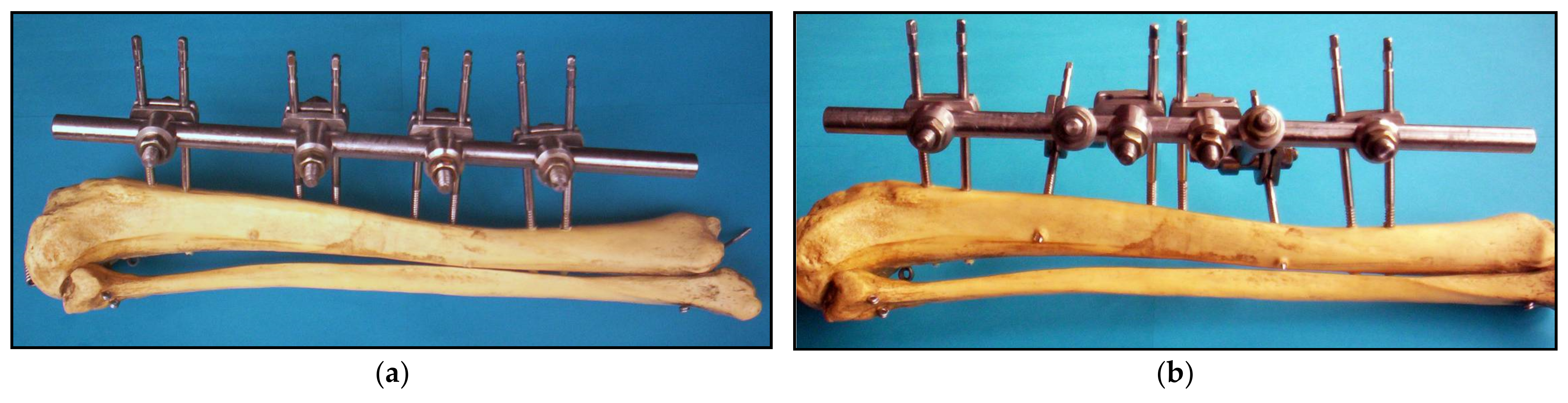
B configuration represents the unilateral external fixation device, which is composed of 4 half-pins fastened into upper and lower bone segments (
Figure 1a). All of the half-pins are placed in the anterior posterior plane (AP plane) parallel to each other. Configuration B is mainly used for the tibia and upper extremities.
C configuration represents the biplanar external fixation device also composed from 4 half-pins fastened into upper and lower bone segments (
Figure 2b). Unlike B configuration, this configuration has an additional half-pin on the upper and lower segment, respectively, fitted into a plane that forms a 45-degree angle with the AP plane. This way, half-pins are located in two planes, and, along with other components, they form a so-called triangular, i.e., delta, construction used for biplanar fixation of the bone segments.
During development of the Sarafix device with composite frame, special focus was directed to frame geometry, i.e., dimensions, which need to correspond to dimensions of the frame built from stainless steel. The material chosen for the composite frame is a recommended composite material with carbon fibers used for these types of constructions. Mechanical properties of the composite material used for frame construction are shown in
Table 1.
Before the experiment was conducted, it was necessary to manufacture the models of the human tibia bone that would be used for the Sarafix device application. Often used materials for bone models are PVC materials, wood, aluminum, copper, etc. This research considers human bone model made out of beech tree with mechanical properties similar to the human bone (
Table 1) [
26,
27]. The final form of the Sarafix device with the composite frame applied to the bone models is shown on
Figure 2.
3. Finite Element Model and Structural Analysis of Fixators
Model formulation implies the selection of the geometric, physical, mathematical and numerical approximation of the phenomena. The goals of the practical (not just qualitative) analysis restrict the number of possible models. Appropriate model selection is not always easy, since more complex models are also more efficient, but less effective.
Models of the fixation device and tibia bone are discretized with linear (TE4) and parabolic (TE10) tetrahedron finite elements in the CAD/CAM/CAE system CATIA. A linear tetrahedron (TE4) is a finite element that belongs to the group of CST (constant strain tetrahedronal) elements so that the deformation components in the element are constants. Namely, the interpolation functions of displacement within an element are linear functions of node displacement. Therefore, TE4 finite elements were used to discretize the fixator components that are predominantly loaded by pressure and tension without the presence of bending and complex stresses. These are small couplings, clamping ring, clamping plates, nuts and bone models.
On the other hand, a parabolic tetrahedron (TE10) is an LST (linear strain tetrahedronal), whose interpolation functions of displacement are second-order polynomials. Therefore, TE10 finite elements were used to discretize the fixator components that are predominantly loaded by bending and complex stresses. These are the frame, the half-pins and the big couplings.
Linear tetrahedron contains four nodes in the vertexes and has 12 degrees of freedom. A parabolic tetrahedron is actually a curve-lined tetrahedron which has 10 nodes and linear strain rate inside the element. The FEM model of the fixation device is discretized with 120.953 TE4 finite elements (46.7%) and 109.816 TE10 finite elements (42.4%). Both of these elements correspond to group of 3D (three-dimensional) iso-parametric elements, i.e., solids with six edges. Approximation of the geometry and the field of the basic unknown variables for the iso-parametric elements is founded on the interpolation functions. Every node of these elements has 3 degrees of freedom.
Connection between the parts of the fixation device (fastened, contact and pin connections) as well as supports (sliding connection) are modeled with the Spider type of elements (28.232 finite elements, i.e., 10.9%). Accordingly, the FEM model of the fixation device has a total of 259,001 finite elements with 262,665 nodes, which results in 787.959 degrees of freedom (
Figure 3).
The device shown in
Figure 1 is completely manufactured from stainless steel used for medical purposes. FEM analysis treats this material as isotropic and linearly elastic. Isotropic materials consider constitutive relations, i.e., stress–strain relations, with following constants: modulus of elasticity and Poisson’s coefficient, which have value of E = 215 ×10
9 Pa i ν = 0.29, respectively.
The device shown in
Figure 2 is manufactured from stainless steel (couplings, coupling carriers and half-pins) and composite material (device frame). As already mentioned, for the FEM model, stainless steel is treated as isotropic and a linearly elastic material, while composite is considered to be an-isotropic, and with cylindrical symmetry of its structure, it can be regarded as orthotropic material, which has attributes defined in three different planes defined with the transversal, tangential and radial cross-sections of the frame.
Models of the bone segments are made out of beech tree with known mechanical properties (
Table 1). This material belongs to the an-isotropic material group, and with the cylindrical symmetry attribute of the bone model, it can be viewed as orthotropic material.
For the composite material and the bone segment material, it is common to predefine parameters such as modulus of elasticity, Poisson’s coefficient and sliding modulus (
Table 1).
During its application, fixation device is influenced by complex stress state, i.e., combination of a pressure, bending and torsion. Most of the conducted studies, with usage of FEM or an experimental method, are based on separated load conditions, meaning research of the fixation device is carried out separately for pressure force, AP bending and torsion [
2,
14,
16,
28]. This study considers pressure force load.
A developed FEM model “mirrors” the experimental investigation of the fixation device under the axial pressure load. During examination, bone models are supported with spherical joints, while the axial pressure force is variable and has a value of
with an increment rate of 2 N/s. Load intensity corresponds to the actual load applied on the fixation device, for the case of patient treatment, and provided value is defined with the results obtained from in vivo examinations [
10,
29].
Structural analysis was performed with following assumptions: the load is quasistatic, supports are modeled with frictionless joints, fastened connection property is established between the half-pins and the bone segments and bone material characteristics correspond to beech tree mechanical properties.
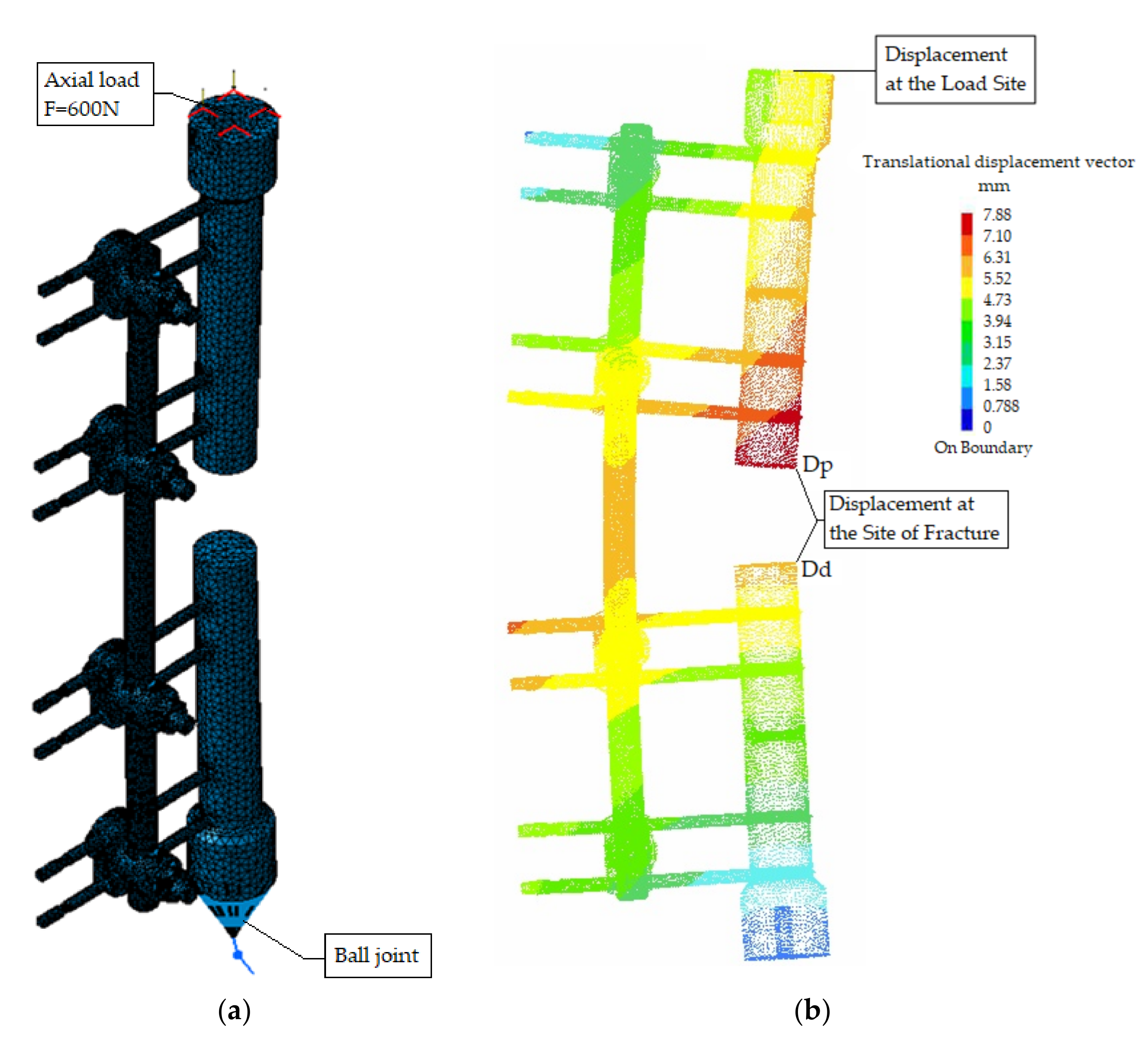
While performing the structural analysis, deflection values in the load zone were monitored (
Figure 4). These values are used to define the stiffness of the fixation device construction as a ratio of the applied load and the deflection values. Stiffness of the device construction under the impact of the axial pressure is calculated with following relation [
25,
26,
27,
28]:
where:
Figure 4.
FEM model (B50) in structural analysis; (a) preprocessing, (b) postprocessing.
Figure 4.
FEM model (B50) in structural analysis; (a) preprocessing, (b) postprocessing.
In order to define the stiffness of the fracture, displacements for the adjacent pair of points on the distal and proximal fracture planes are determined in the x, y and z directions. For these points, the resultant vector of the relative displacement (R) has the maximum value.
Intensity of this vector is described with the following [
2,
14,
16]:
Relative displacements for the pair of points on proximal and distal bone segment planes in
x,
y and
z directions are determined as [
30,
31]:
where:
, i —relative displacements of the bone segment points in x, y and z directions (mm);
, i —displacement of the proximal bone segment in the x, y and z direction (mm);
, i —displacement of the distal bone segment in the x, y and z directions (mm).
Stiffness of the fracture is defined as a ratio of the applied load and the resultant interfragmental displacement of the bone segments [
32,
33]:
Figure 4 shows the FEM model of the B50 device configuration after preprocessing. The end of the upper bone segment is loaded with an axial force, i.e., surface force in the
z direction. Translations in directions
x and
y are restricted in order to simulate the device load via the spherical joints.
Movement of the lower part of the fixation device model is restricted with the ball joint property, where the lower bone segment is connected with the bone model via the smooth virtual part property. Displacements of the described FEM model setup under the impact of axial load are show in
Figure 4b.
Apart from the displacement determination, complete structural analysis requires an insight of the principal stresses in characteristic zones of the fixation device [
27,
28]. Structural and experimental analysis requires monitoring of intensities and the directions of the principal stresses in the two control zones of the device construction. Control zones are located at the closer side to the bone (MM−) and opposite side (MM+), as shown in
Figure 5.
Axial pressure force, applied on the proximal bone segment, causes complex stress distribution on the fixation device frame, which is a combination of bending and axial pressure. This complex stress distribution is manifested with unequal stress distribution of the axial stresses, i.e., the elastic line of the frame cross-section does not match with the axis of symmetry.
Intensities and the directions of the principal stresses for the B50 configuration of the Sarafix device are shown in
Figure 5a, while
Figure 5b shows the von Mises stress distribution.
The value of the maximum principal stress (σ
1) in the control zone MM+ is significantly greater than the values of other principal stresses (σ
2 and σ
3), meaning the von Mises stress value is equal to the maximum principal stress value (σ
1) (
Table 2). For the other control zone, principal stress (σ
3) has significantly greater values than two other principal stresses by the means of the absolute value, so in this case, the von Mises stress is equal to the principal stress (σ
3).
4. Experimental Testing of Fixators
Experimental research was conducted in vitro, and necessary data were obtained with the material testing machine with usage of appropriate measuring equipment and side-tools used for supporting of the model (
Figure 6). The goal of the experimental setup was to verify the structural analysis results.
In real conditions, a fixation device is loaded via bone segments. Considering that fact, the experimental load of the fixation device was applied throughout the models of the bone segments [
24,
31,
34].
Figure 6 shows the experimental setup for the Sarafix fixation device.
Supporting of the ends for the upper and lower bone models was carried out with spherical joints mounted on the force transducer and lower side-tools. One of the side-tools was fixated to the base of the testing machine. Its upper part contained the spherical joint, which “grabbed” the lower bone model segment. The upper mobile side-tool also contained a spherical joint, which was connected with the force transducer.
During the examination, deflection of the proximal bone segment model was monitored with the deflection transducer, while load was controlled with the force transducer (U2A by the HBM manufacturer—Hottinger Baldwin Messtechnik GmbH, Darmstadt, Germany), and with the usage of the material testing machine (Zwick GmbH & Co., model 143501, Ulm, Germany). Deflections of the bone segments at the fracture zone were monitored with the digital high-speed CMOS camera (PCO AG, type: pco. 1200 s, Kelheim, Germany) (
Figure 6).
Stress analysis was performed with the strain gauges of type 3/120LY11 (HBM) and a data acquisition electronic device system QuantumX MX840B (HBM), used for signal receiving from the strain gauges. Strain gauges were connected into the Wheatstone’s quarter-bridge configuration and with the QuantumX system via two measuring channels.
Quarter-bride configurations were composed from active and compensation strain gauges, as shown in
Figure 7. Active strain gauges were applied on the opposite sides of the frame, i.e., MM- and MM+ control zones (
Figure 7). This way their longitudinal axis matched the direction of the maximal principal strain.
Compensation gauges are used to compensate the temperature effects, and they are the same type as the active gauges. Compensation gauges were mounted on a plate that was connected to the frame in an area near the control zones. The plate and fixation device frame were made out of the same material. After their application, all of the gauges were protected from the mechanical defects using the sealing tape.
The fixation device frame, due to axial pressure load, was exposed to the eccentric pressure. This caused the specific principal strain condition, which is formed by bending strains and axial pressure strains (
Figure 8). Using the superposition method, these strains can be defined as:
where
is the strain component caused by the axial compressive force,
the strain component caused by the bending moment, F the axial compressive force, A the area cross-section of the fixator connecting rod, E modulus of elasticity, M bending moment and Z section modulus of the fixator connecting rod.
In this case, the bending strains are significantly greater than the pressure strains. Therefore, this form of a load is manifested with an unequal distribution of the main strains, i.e., the neutral axis does not match with the frame symmetry axis (
Figure 8).
Strain registered with the Wheatstone’s bridge configuration is as follows [
27]:
whereas
i
are output and power supply voltages, and
is the strain gauge factor.
On the basis of the obtained data for the control zones (
i
) and known modulus of elasticity of the fixation device frame, and with usage of the Hooke’s law for the one-axis stress condition, intensities of the principal stresses for the control zones are:
Acquisition, processing, monitoring and analysis of the data obtained with the QuantumX system are performed with the DAQ Catman software (HBM).
6. Discussion
Biomechanical properties of the external fixation device have a significant impact on the fracture treatment process by the means of influencing fracture environment. The basic task of the external fixation is to stabilize the fracture during the patient treatment. This paper presents a comparative analysis of the biomechanical performances of the Sarafix fixation device under the impact of the axial load for different frame materials and device configurations.
It is important to note that during experimental measurements, measures may be subject to some degree of systematic measurement error and therefore result in the introduction of bias into the study. In order to reduce the measurement error, during the process of experimental tests for each of the analyzed designs, five measurements of the load-displacement and load–stress dependence were performed. Based on the measurements, the mean values of the observed quantities were determined.
In addition, since the research was conducted in laboratory conditions, we used a human bone model made out of beech tree with mechanical properties similar to the human bone. This limitation is likely to have a negligible impact on results when human testing is performed in the future.
By analyzing the displacement values in the load zone, regarding the configuration aspect, it is noticeable that the B50 configuration has lower displacement values compared to the C50 configuration for the stainless steel frame. For the carbon frame, the results give the opposite conclusion, i.e., the B50 configuration has greater displacement values compared to C50.
If same displacement values are analyzed from the material aspect, it can be observed that fixation device with composite frame has much greater displacements compared to steel frame, which amount to about 38% (for the B50 configuration), i.e., 9.3% (for C50 configuration). By comparing the results of the transversal displacements for the bone segment models, regarding the device configuration aspect, it can be stated that for the steel frame case, the B50 configuration has lower displacement values than the C50 configuration. For the carbon frame case, opposite statements can be drawn.
By analyzing the transversal displacement results, from the frame material aspect, the same statements can be drawn for the load zone displacements. The carbon frame device has greater displacement values at the load zone, with an approximate value of 30% (B50 configuration), i.e., 15% (C50 configuration).
Stiffness of the fracture zone was determined on the basis of the relative bone segment models’ displacements at the fracture zone, while the Sarafix device stiffness was determined on the basis of the bone segment models’ displacements at the load zone. In the absence of greater rotations, plastic deformations and sliding conditions, which is a basic task for conservation of the fragment’s anatomic reduction, studies have shown that there is a linear correlation between the applied load and bone fragment displacements.
By analyzing the values of the device stiffnesses for the different configurations, it can be noted that stiffness values do not differ much in the case of the steel frame. Sama analysis performed for the case of the carbon frame shows that stiffness of the C50 configuration is 21% higher compared to the B50 configuration. Same statements are drawn for the fracture stiffness, as well. Stiffness values for the steel frame configurations are almost matching, while carbon fiber configurations are distinguished by a 10% greater fracture stiffness for the C50 configuration compared to the B50 configuration.
Regarding Equations (1) and (4), it is obvious that stiffness values for the carbon frame configurations are lower than values for the steel frame configurations, due to greater displacements at the load and fracture zones. By comparing the values from the
Table 2, it is noticeable that the carbon frame device configuration has 28% lower construction stiffness than the one with the steel frame (for the B50 configuration), i.e., 9% (for the C50 configuration). In addition, fracture stiffness values for the composite frame application are approximately 23% lower (B50 configuration), i.e., 13% lower (C50 configuration), compared to steel frame.
Analysis of the stress results on the critical zones of the construction leads to a following statement: the carbon frame device has about 33% lower stresses at the critical zones compared to the steel frame at the control zone MM+ and, similarly, 35% lower stresses at the control zone MM−.


 ,
, 


