Article

Modeling Joule Heating Effect on Thermal Efficiency of Photovoltaic Thermal (PVT) Collectors with Operation Mode Factor (OMF)

Graduate School of Renewable Energy, Darma Persada University, Jl. Radin Inten 2, Pondok Kelapa, East Jakarta 13450, Indonesia
Appl. Sci. 2022, 12(2), 742; https://doi.org/10.3390/app12020742
Submission received: 29 November 2021 / Revised: 31 December 2021 / Accepted: 3 January 2022 / Published: 12 January 2022

Abstract

:
The purpose of the present study is developing the operation mode factor (OMF) by remodeling the thermal efficiency model of a hybrid PVT collector during steady state. Joule heating occurs when the photovoltaic (PV) panel operates at a high current during maximum power point tracking (MPPT) on higher irradiation. Under these conditions, some electrical energy converts to thermal energy within the PV cells. Joule heating contributed to increasing the PVT thermal efficiency. The steps were to construct the OMF by remodeling the thermal efficiency involving the Joule heating effect and to validate the results using the model by comparing the simulation and experiment. The dimensionless OMF was responsible for changes in thermal efficiency for PVT-mode. The conductive heat transfer coefficient from the surface to the absorber was the most decisive component in the OMF. Heat removal factor and OMF might be interrelated at the mass flow rate by decreasing PV temperature to maintain Joule heating. The proposed model with OMF had explained PVT-mode and T-mode with the RMS value of less than 1%. This model complemented the results of the previous studies. The results may contribute from the initial design to the operational monitoring for thermal to electrical energy production.

1. Introduction

Solar energy is an abundant source of renewable energy. It can convert directly into electrical energy by a photovoltaic (PV) module, thermal energy with a solar thermal collector, and electrical and thermal energy simultaneously with a hybrid photovoltaic (PVT) collector. A hybrid PVT collector attaches a PV module on the top of a flat-plate-type thermal collector [1]. The original idea was to control the PV module temperature as low as possible to maintain the electrical performance [2]. The thermal collector takes the heat from the PV module by circulating fluids, such as water and air. Thus, the total solar energy converted to electrical and thermal energy by the PVT collector can reach 60–70% [3]. The thermal energy generated by hybrid PVT collectors is applicable for low-temperature applications, such as domestic hot water and low-temperature industrial processes, or space heating [4,5].
Over the years, researchers have studied hybrid PVT collectors in various aspects. They have developed the design constructions, operational parameters, materials selection, system configurations, modeling simulation, and system performance [6]. The system performance of the PVT systems is still an interesting topic for researchers. Those aspects strongly influence the performance of the PVT system. The market expects the PVT system to be more applicable and cheaper with higher performance. Concerning the thermal efficiency η t of PVT collector [7,8], formulated as;
η t = F R τ α F R U L ( T i T a ) I
The PVT is influenced by heat removal factor F R , transmittance τ , absorptance α , optical efficiency η o or τ α , overall loss coefficient U L (in W/m2.°C), inlet water temperature T i (in °C), ambient air temperature T a (in °C), and irradiance I (in W/m2). The collector system has high performance, indicated by the high τ α and low U L (see Equation (1)). The energy gain part is F R ( τ α ) , while the energy loss part is F R U L ( T i T a ) / I . It is assumed that the PV cell in the PVT collector provides thermal resistance when electricity is not generated [9]. It is essential to determine the correlation between the PV cell without electricity generation and its resistance effect [10].
The thermal performance of the PVT system is influenced by the Joule heating when simultaneously generating electrical and thermal energy (PVT-mode) [11,12]; there is an important factor involved. Specifically, in an effective region [13], the PVT thermal efficiency in PVT-mode is higher than in T-mode. Joule heating has the effect of improving the thermal efficiency up to 13%. Joule heating appears when the PV panel works at a high electrical current during maximum power point tracking (MPPT) at higher irradiation. Joule heating induces a lower increase in the cell temperature. Joule heating is the heat generated when the electrical current passes through the resistive material. A part of the electrical energy in PV cells becomes thermal energy. At the zero reduced temperature, the PVT thermal efficiency in the PVT-mode is higher than in T-mode when generated heat only. With the conditions, T i T a or I is high.
The thermal performance of PVT collectors still attracts the attention of researchers to this day. Various thermal efficiency models have obtained more accurate results. Several numerical models have been used to evaluate the performance of PVT systems in more detail up to three dimensions, assisted by simulations with various conditions, such as steady state, transient, and real time [14,15,16,17,18,19,20,21,22,23,24,25]. Salameh et al. [14] developed a novel three-dimensional numerical model for the thermal efficiency of the PVT system and tested the flow adopting the usual k–epsilon model. The model applied the symmetric convection and boundary conditions for the PVT cooling system. Boumaaraf et al. [15] developed the numerical models for electrical and thermal efficiency using MATLAB simulation. They compared the electrical and thermal performance between a classical PV generator and water glazed PVT collector under northern Sahara climatic conditions. Slimani et al. [18] developed and validated a numerical model of thermal and electrical performance through experimental results indicated in the previous literature. The numerical model took the heat balance equations and different thermal and electrical parameters for each configuration. Simonetti et al. [19] developed a model to simulate a hybrid photovoltaic–thermal collector under a transient regime. The model used a control volume approach. The collector is divided into small elemental volumes where the energy equation is solved using a bidimensional finite difference method. Yu et al. [20] developed a novel 2D irradiance temperature coupling model for the performance of flat-plate PVT systems. M’Sirdi et al. [21] developed a nonlinear state-space model of a hybrid photovoltaic/thermal (glazed and unglazed PVT) system to couple the electrical and hydraulic circuits. The proposed model was used to predict, monitor, diagnosis, and increase the life span. El Manssouri et al. [22] developed the 1D (dimensional) steady-state numerical model and performed the bifluid using MATLAB. It used a commercial WISC PVT collector by adding an air channel, an aluminum absorber with fins, and a layer of thermal insulation. Khelifa et al. [23] established and verified a theoretical model of 22 designs for a concentrating PVT dual-fluid solar collector with 1D steady-state energy-balance equations. The air and water mass flow rates were varied to predict the system performances. Shen et al. [24] developed a theoretical model of the heat transfer in the PVT collector with different parallel cooling channels that was established to evaluate the effect on the thermal performance of the PVT collector. Najafi et al. [25] predicted the thermal efficiency of PVT collector by modifying multilayer perceptron artificial neural network (MLP-ANN), adaptive neuro-fuzzy inference system (ANFIS), and least squares support vector machine (LSSVM) approaches. Boumaaraf et al. [16] developed a mathematical model based on heat transfer balance equations and electrical and thermophysical proprieties to draw the output behavior of both PV module and hybrid PVT water-based system. Sahlaoui et al. [17] developed a numerical analysis and experimental validation of the thermal and electrical behavior of the air PVT collector based on the geometric design and the Tunisia climate conditions. The thermal modeling used the heat balance equations of each component. Das et al. [26] developed a novel thermal model for a PVT system which includes the thermal contact resistance between the layers of a PVT system and individual resistance. This model provides a clear understanding of how the properties of each layer influence their overall performance.
From those studies, numerical and theoretical models have predicted the thermal performance of PVT collectors with a certain complexity and flexibility. However, they have not included the effect of Joule heating, or Joule heating has not been the focus of the discussion. As a result, they have not explained the Joule heating effect on the thermal performance of a hybrid PVT collector. The commonly used thermal efficiency model has not also covered the Joule heating effect [7,8]. A factor needs to be involved and proved empirically in the thermal efficiency model used to explain the Joule heating effect on thermal efficiency in PVT-mode. A performance analysis was carried out for the previous result in steady-state [13]. The purpose of this study is to develop the operation mode factor (OMF) by remodeling the thermal efficiency model of a hybrid PVT collector during steady state.

2. Materials and Methods

2.1. Experiment Setup

Figure 1 shows the previous outdoor experiment to observe the Joule heating effect by experimenting with PVT-mode and T-mode alternately [13]. From the experimental setup in Figure 1a, the PVT collector faced south from the Kanagawa Institute of Technology campus, Atsugi—Japan, at a 50° tilt. For constant temperature setting and single flow rates ( m ˙ = 6.7 × 10 m3/s ≈ 4 L/min), the water circulation system used a temperature-controlled water chamber connected to a pump and flow meter. The heat exchanger system took heat from the outlet water collector before entering the water circulation system. The experiments took place during sunny days in winter, with four inlet water temperatures T i = 12; 15; 20; and 25 °C. The data of irradiation I from pyranometer, wind speed V w from anemometer, inlet water temperature T i , outlet water temperature T o , ambient air temperature T a , voltage V m p p , and current I m p p were collected by a data logger every 30 s. Data collection was focused during 12:00–13:00 to ensure stable irradiation and ambient air temperature. The experiments were run before and after that period to avoid the hysteresis effect on the PVT collector. Figure 1b shows the PVT array 2 × 2 connected in series for higher power output to provide a higher Joule heating effect. The experiment used polycrystalline silicon (p-Si) PV modules. Each PV module covered the top of the thermal collector. The numbers indicated the water flow from 1 (as inlet)—2—3—4 (as outlet). Figure 1c shows the construction of the PVT collector. Each PVT collector is 790 mm × 820 mm, or 0.60 m2. Each PV module area A p v is 780 mm × 770 mm or 0.58 m2. The total area of the PVT collector A c is 2.40 m2. A more detailed setup was given by [13].

2.2. Construction of Operation Mode Factor (OMF)

The construction operational mode factor (OMF) was obtained by remodeling the thermal efficiency model as shown in Equation (1) to the thermal efficiency results in [13]. Joule heating is involved in the results. As the previous results were carried out outdoors with the wind loss effect due to wind convection, it was then added back to the system to become the without wind loss effect (ideal condition).
Figure 2 shows the model analysis of the current PVT system: a simple solar energy balance during PVT-mode is shown in Figure 2a and its thermal simplification in Figure 2b. The analysis assumed that (1) the hysteresis effect was neglectable due to the system being in a steady state, (2) the surface temperature, T S (°C) was consistent throughout the glass layer area, (3) the glass layer did not permeate the sun’s heat, (4) the layer of the backside absorber was appropriately insulated, (5) the adhesive had excellent electrical insulation and thermal conduction [27], (6) the τ α was considered unchanged for T-mode and PVT-mode, and (7) the temperature of a silicon solar cell was constant along the direction perpendicular to the glass plate.
For overviews, there are differences in addressing PV cells as a reference. Florschuetz [7] treated the PV cells as the absorber, and included the radiation effect between the glass plate and the other surface forming the flow passage and the convection effect between the surface and the collector fluid. As assumed, no heat transfer occurred via the PV cells. It may give lower heat transport from the fin to the tube to lower the efficiency. The thermal resistance reduces, while thermal conductivity increases, in the absorber. These increase the electrical and thermal conversion into usable heat and release it to the water fluid Q t h . It is changed into electricity and channeled to the load Q e . The remaining losses leave the system (W) and never become absorbed by reflection Q r e f and by radiation Q r a d , discharged to the air as convection loss Q c o n v .
Here,
Q s = Q p v t + Q l , t o t
where Q p v t is the PVT solar conversion and Q l , t o t as the total losses. Here, Q p v t is the total solar conversion by the PV layer Q p v and the thermal layer Q t h , so
Q p v t = Q t h + Q p v
In this analysis, the Q p v generates both Q e and Q i h .
Q p v = Q e + Q i h
Both PVT and T-mode, the electrical-internal heat, Q i h , consequently enter the PVT system as the usable heat Q i h , t h or as the loss heat Q i h , l , so
Q i h = Q i h , t h + Q i h , l
Then, the total energy losses Q l , t o t is expressed as
Q l , t o t = Q r a d + Q c o n v + Q r e f + Q i h , l
Here, the energy balance for the PVT collector from the source of solar cell energy, with a size A c of 1 m2, can be expressed as follows:
Q t h + Q e = A c I τ α
From Figure 2, the PVT collector expresses heat balance at the silicon solar cell as follows:
Q t h = Q u , t h + Q i h , t h + Q l , t o t
where Q t h is the thermal energy absorbed by the surface of PVT collector A c (m2), with the heat transfer coefficient from the surface to an absorber of PVT collector K S A (W/m2.C) and the temperature difference between the surface and fluid of PVT, T S and T f (°C), respectively. Here, in steady state, the absorber temperature T A = T f .
Q t h = K S A A c ( T S T f )
As T f is the medium fluid temperature between the inlet T i and outlet T o to/from the collector, which is
T f = ( T i + T o ) / 2
or as an inlet water temperature T i ;
T i = 2 T f T o
then Equation (9) also can be expressed as
Q t h = K S A A c ( T S T i )  
Then, Q l , t o t is the loss of A c (m2) with the overall heat loss coefficient of PVT U L (W/m2.C) and the temperature difference between T s (°C) and the ambient T a (°C).
Q l , t o t = U L A c ( T S T a )
Then, Q t h is expressed as
Q t h = K S A A c ( T S T i ) + U L A c ( T S T a )
Substituting Equation (14) into Equation (7) and then dividing by A c I , results in the thermal efficiency η t ;
η t = ( τ α η e ) U L ( T S T a ) I
To obtain T S in Equation (15) by substituting Equation (7) into Equation (14), the result is inserted into the loss part of Equation (15).
η t = K S A K S A + U L ( τ α η e ) K S A U L K S A + U L ( T i T a ) I
or
η t = K S A K S A + U L { ( τ α η e ) U L ( T i T a ) I }
Equation (1) is modified to be Equation (17) for T-mode and PVT-mode analysis. The product τ α is assumed to be 0.81 [28]. The practical value of η e is provided by Equation (25), based on experimental results [29,30]. As shown, Equation (17) is integrated with η e and the dimensionless operation mode factor (OMF):
O M F = K S A / ( K S A + U L )
OMF is the ratio between the heat transfer coefficient of useful energy K S A to the sum of the heat transfer coefficient K S A and the overall heat loss U L . Because of the different operation modes, then the OMF in Equation (17) is distinguished by
T - mode :         O M F t = K S A , t / ( K S A , t + U L , t )           and           PVT - mode           O M F p v t = K S A , p v t / ( K S A , p v t + U L , p v t )

2.3. Validation

The results for the currently developed model are validated by comparing the thermal efficiency from simulation η t , s i m with the thermal efficiency from regression η t , r e g from Equations (21)–(24) by using a root mean square (RMS) percentage deviation:
R M S s r =   [ 100 x ( η t , s i m η t , r e g ) / η t , r e g ] 2 n                 R M S s e =   [ 100 x ( η t , s i m η t , exp ) / η t , exp ] 2 n               R M S r e =   [ 100 x ( η t , r e g η t , exp ) / η t , exp ] 2 n
where n is the number of data points observed. Previously, there was an actual thermal efficiency from the experimental results η t , exp . Now, there are two types of thermal efficiency available to examine RMS. It can be combined to find out the other value of RMS. The experimental values of thermal efficiency η t , exp are as previous experimental results [13], including solar radiation intensity, ambient temperature, inlet and outlet water temperature, water mass flow rate, PV surface and back temperature, wind velocity, electrical power, etc. The operational parameters, inlet water temperature, and water mass flow rate improve the system performance [31].

3. Result and Discussion

3.1. Reconstruction Thermal Efficiency with Operation Mode Factor (OMF)

The linear regression solved Equation (21) for T-mode and Equation (22) for PVT-mode for the wind loss effect [13]. In the same way, it was also repeated for T-mode and PVT-mode for the without wind loss effect on Equations (23) and (24). Equation (20) calculated the RMS value. Table 1 summarizes the results. Equation (17) uses the required parameters in Table 1 to prove the simulation using the results in [13]. Those parameters completed the ratio between PVT-mode to T-mode, such as O M F p v t / O M F t , K S A , p v t / K S A , t , U L , p v t / U L , t .
Wind loss effect (from actual measurement):
T - mode :             η t = 49.5 1726.2 ( T i T a ) I
PVT - mode :   η t = 56.7 3028.1 ( T i T a ) I
Without wind loss effect (ideal condition):
T - mode :             η t = 54.0 1556.7 ( T i T a ) I
PVT - mode :   η t = 60.3 2900.3 ( T i T a ) I
The electrical and thermal efficiency complemented the correlation analysis. At steady state and MPPT [13], electrical efficiency as a function of collector surface temperature T S :
η e = 14.21 0.0547 T S
with the R2 = 0.811. η e theorizes as
η e = η r ( 1 β ( T S T r ) )
where β is the efficiency temperature coefficient. For a crystalline PV module, β ≈ 0.0045. η r is the PV reference efficiency at the reference temperature T r = 25 °C.

3.2. Simulation

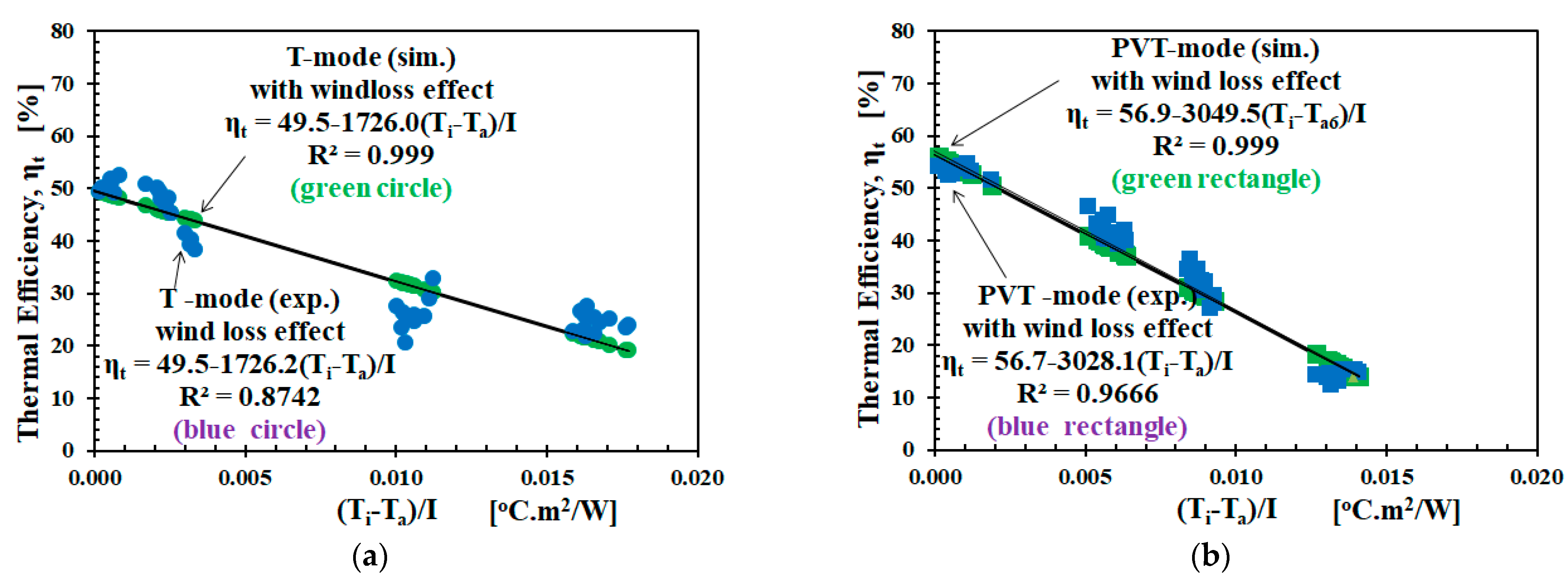
Figure 3 shows the PVT performance in thermal efficiency η t versus the reduced temperature parameter ( T i T a ) / I for wind loss effect; (a) T-mode and (b) PVT-mode. From Figure 3a, the T-mode simulation is represented by the black circle markers while the T-mode experiments by the white circle markers. The trend line for both T-modes crossed each other, with the slope η t / ( T i T a ) / I ≈ 1726.0 for the simulation and 1726.2 for the experimentation. For Figure 3b, PVT-mode simulation is represented by the black rectangle markers, while the PVT-mode experiment is by the white rectangle markers. The trend line for both T-modes also crossed with the slope η t / ( T i T a ) / I ≈ 3049.5 for the simulation and 3025.1 for the experimentation. Based on Equation (20), the R M S s r values of the η t . s i m to η t . r e g were 0.82% for T-mode and 0.00% for PVT-mode, giving an average of 0.4%, whereas the R M S s e values of the η t . s i m to η t . exp for T-mode and PVT-mode were 16.3% and 10.9%, with an average of 12.9%.
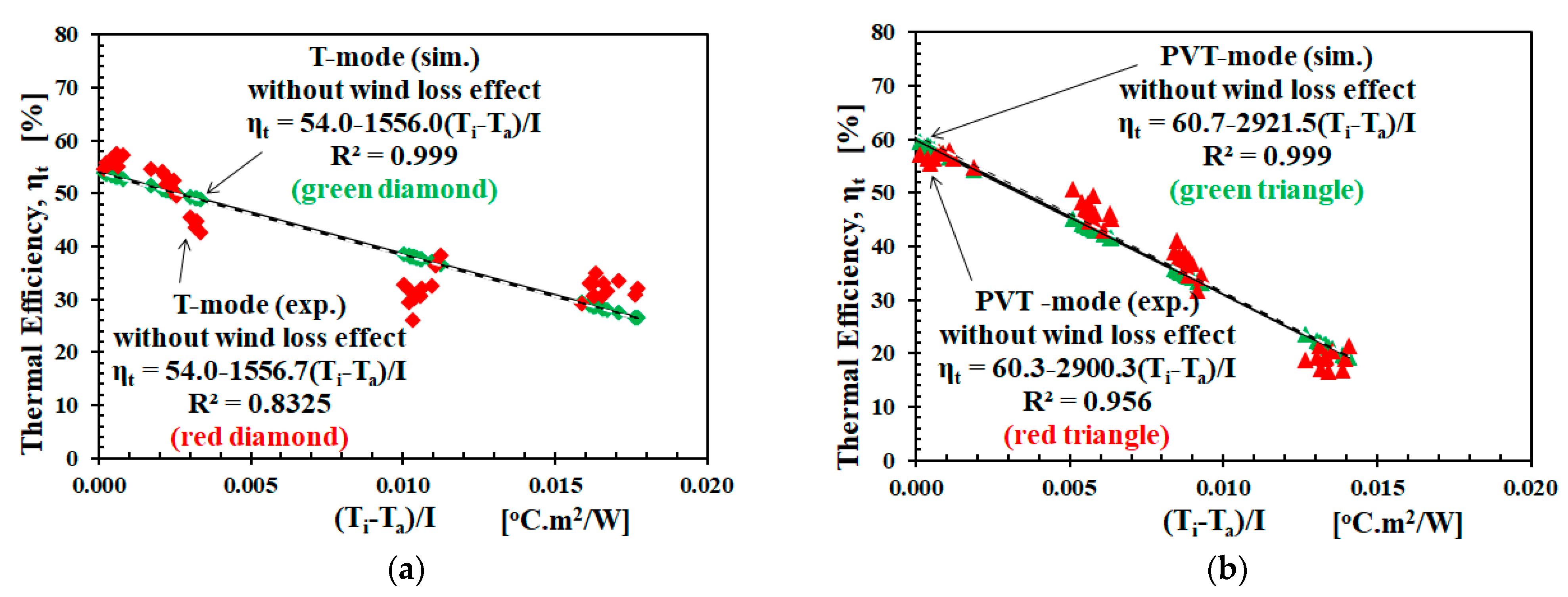
Figure 4 shows the PVT performance of thermal efficiency η t versus the reduced temperature parameter ( T i T a ) / I for without wind loss effect; (a) T-mode and (b) PVT-mode. In Figure 4a, the T-mode simulation is represented by the black diamond markers, while the experiment is by the white diamond markers. The trend lines for both T-modes crossed each other, with the slope η t / ( T i T a ) / I ≈ 1556.0 for the simulation and 1556.7 for the experiment. For Figure 4b, PVT-mode simulation is represented by the black triangle markers, while the PVT-mode experiment is by the white triangle markers. The trend lines for both T-modes also crossed, with the slope η t / ( T i T a ) / I ≈ 2921.5 for the simulation and 2900.0 for the experimentation. Based on Equation (20), the R M S s r values of the η t . s i m to η t . r e g are 0.02% for T-mode and 0.74% for PVT-mode, giving an average of 0.4%, whereas the R M S s e values of the η t . s i m to η t . exp for T-mode and PVT-mode were 10.2% and 14.0%, with an average of 12.1%.
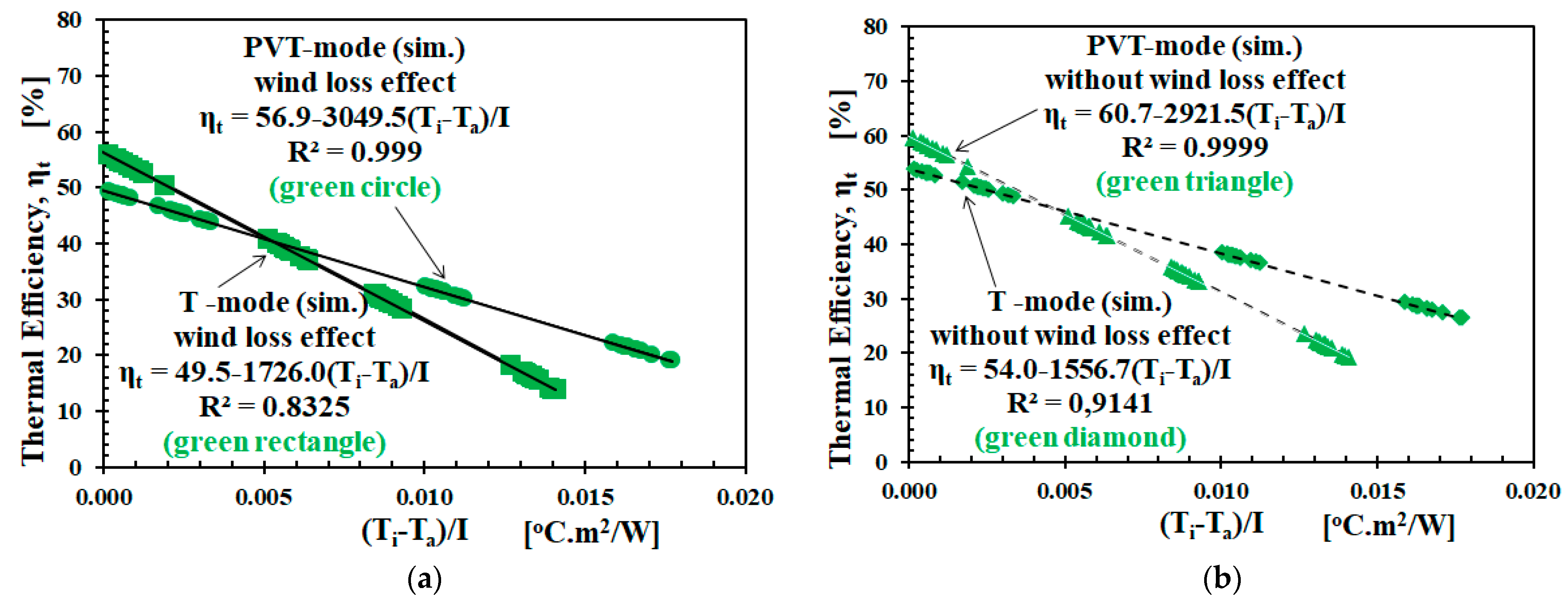
Figure 5 shows the PVT performance of thermal efficiency η t versus the reduced temperature parameter ( T i T a ) / I of simulation results for (a) wind loss effect and (b) without wind loss effect of T-mode vs. PVT-mode. From Figure 5a,b, the trend line of T-mode versus PVT-mode crossed each other. For the wind loss effect, the crossing point was η t = 39.8% and ( T i T a ) / I = 0.0056, whereas for the without wind loss effects, at η t = 46.4 and ( T i T a ) / I = 0.0049. The cross point was not much different compared to the results of the experiment; η t = 40.0% and ( T i T a ) / I = 0.0055 for the wind loss effect, or η t = 46.7% and ( T i T a ) / I = 0.0047 for the without wind loss effect [13]. The total efficiency of PVT, η p v t = η t + η e , at these crossing points are approximately 52.3% and 58.9% for wind loss effect and without wind loss effect, respectively. The area between 0 and the crossing point was called the effective region [13].
Figure 6 more specifically describes electrical efficiency versus thermal efficiency for the PVT-mode (simulation) versus the T-mode (simulation). Using Equation (25) to calculate η e based on T S , which was conducted simultaneously [2]. η e as a function of T S was plotted into the graph η t versus ( T i T a ) / I as the X-axis, as well as η e versus ( T i T a ) / I . As shown in the graphs, η e also decreased for ( T i T a ) / I > > 0 , as well as for T S > > 0 in Equation (25). Suppose the lowest η t occurred at ( T i T a ) / I for Figure 6a, then η e only lost 0.24% from 12.9% at ( T i T a ) / I = 0 . Suppose the cross point occurred at ( T i T a ) / I = 0.05 for Figure 6b, then η e only lost 0.79% from 12.9% at ( T i T a ) / I = 0 . When ( T i T a ) / I > > 0 , η e was smaller, the Joule heating effect was also low. Joule heating was only effective in increasing thermal efficiency in the interval with 0 ( T i T a ) / I 0.05 as the effective region.
For more details, Table 2 summarizes the complete parameters as the result of the simulation analysis in Figure 3, Figure 4, Figure 5 and Figure 6, such as K S A , U L , η t , ( T i T a ) / I , RMS, etc. There was no significant difference between Table 1 and Table 2. That is, the OMF component of the experiment and the simulation provided almost identical values.
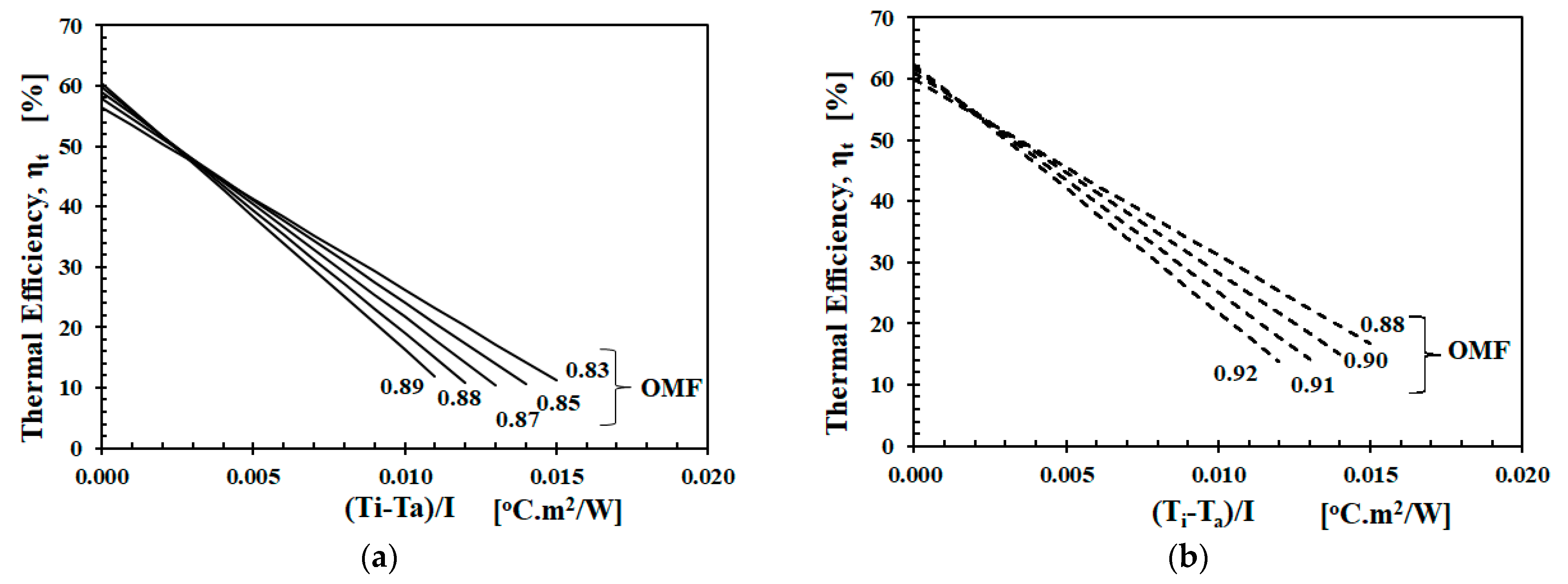
K S A U L η t ( T i T a ) / I = 0 ( T i T a ) / I     η t = 0 η t / [ ( T i T a ) / I ] R M S ( r e ) R M S ( s e ) K S A / U L O M F F R O M F p v t / O M F t K S A , p v t / K S A , t U L , p v t / U L , t Figure 7 shows the simulation results of thermal efficiency versus reduced temperature for without and wind loss effect. The OMF values were varied by increasing the values of K S A and U L proportionally. Then, the results were simulated for thermal efficiency. As seen in Figure 7a for the without wind loss effect, increasing OMF of 0.06 from 0.82 to 0.89 has the potential to increase the thermal efficiency by 3.9%. Figure 7b for the wind loss effect, shows increasing OMF of 0.04 from 0.88 to 0.92, potentially increasing the thermal efficiency by 2.7%.

4. Discussion

A simple, steady-state, one-dimensional thermal efficiency model has constructed the proposed thermal efficiency model with the influence factors. The result was validated and tested during T-mode and PVT-mode using the original experimental data [13]. Based on the results, OMF can explain the crossing of thermal efficiency lines between T-mode and PVT-mode. For more details, let us discuss some findings here.
First, to understand the most decisive component of OMF we compare PVT-mode with T-mode. As shown in Table 2, K S A , p v t / K S A , t = 4.06 and 5.51, then U L , p v t / U L , t = 1.30 and 1.41 for wind loss effect and without wind loss effect, respectively. K S A changes more significantly than U L . In other words, K S A was the most decisive component in OMF, which gives O M F p v t / O M F t = 1.36 and 1.33 for with and without wind loss effect, respectively. The reason for the K S A changes is as follows: during steady-state, when a load variation took place with the ambient air temperature remaining constant, the different loads had an effect on the overall conduction coefficient. Then, the temperature gradient across the PV surface would change, which means that the overall thermal conductivity of the PVT collector changed. Based on formula and value, OMF might correlate to F R . The empirical relation between F R and OMF may need to be studied further [32]. For the cases of wind loss effect and without wind loss effect, the RMS (sim.) value of PVT-mode of 10.6% was smaller than the T-mode of 15.2%.
Second, the PVT-mode thermal efficiency is greater than T-mode in the effective region, as shown in Figure 6b through K S A / U L (refer to Equations (12) and (13), and K S A / U L = Q u , t h ( T S T a ) / Q L , t o t ( T S T i ) ). As shown in Table 2, the K S A / U L of T-mode and PVT-mode for the wind loss effect are 1.57 and 4.92, or 2.0 and 7.81 for the without wind loss effect. The reasons why K S A / U L for PVT-mode was bigger than T-mode (in the effective region) can be explained as follows. Apart from heating, radiation entering a solar cell separates the electrons from their atomic bond. It produces the electron–hole pairs due to the PV conversion of a photoelectric current flow in the circuit. The bandgap decreases with temperature. Through thermal activation, more electrons cross the energy gap. These cause the dark current to increase. The open-circuit voltage decreases. Then, the thermal resistance of the absorber decreases, though the thermal conductivity increases. Finally, the electrical and thermal efficiency increase. As assumed in the Materials and Methods section, the PV cell in the PVT collector provided thermal resistance due to the additional thermal mass of the PV layer [9]. Therefore, there is heat from the internal heating Q i h , t h as expressed in Equation (5). For T-mode, Q i h , t h = 0 .
Third, we see the relation between OMF and F R . Referring OMF to Equation (17) and F R (see Equation (6.7.3) in [33]), OMF may represent F R at Equation (1) for T-mode, but not for PVT-mode. OMF was more triggered by the operation mode (PVT-mode and T-mode) [13], while F R was more influenced by the geometrical design and construction parameters [32,34]. They might be interrelated at the mass flow rate as the effect of decreasing PV temperature, thereby optimizing PV output [35], which maintains Joule heating. By formula, OMF and F R did not seem directly related to each other. However, by involving the previous analysis, OMF and F R might be related to each other. In PVT-mode, the material absorber in K S A might become more conductive or less resistive. Then, from the beginning, it already had the approach to consider the condition with and without wind loss effects. Based on the results and analysis with the approach, the top-loss coefficient U t was the most dominant component to change the overall heat loss coefficient U L uring PVT-mode.
Fourth, we explain the difference in RMS values. The value of OMF is less than 1% because it is derived from the regression formula of thermal efficiency. The thermal efficiency with OMF had good agreement with the thermal efficiency regression formula, while the average R M S ( r e ) and R M S ( s e ) for both T-mode and PVT-mode is 12.5%. The deviation between the experimental and theoretical values was due to the fluctuations in data taken during outdoor experiments over several days, which was accommodated in modeling. Even in a steady state, it could not control the outdoor parameters, such as ambient temperature, wind speed, solar irradiance, and other losses. The simple development of OMF from the steady-state thermal efficiency regression formula can give adequate results in explaining both PVT- and T-mode based on original experimental data.
From the Review section, the Joule heating effects on the thermal efficiency of the PVT collector, as shown in [13], have not been discussed by the previous models, although some have been, such as PVT-mode and T-mode [9,11]. However, they have not focused on, or discussed, the Joule heating effect. Some have focused on system performance [11,36,37], performance parameters [38], and design validation [39]. Joule heating effects on thermal efficiency was studied indoors using a hybrid PVT collector [40] and a halogen solar simulator [13] that was made. From the experiment with PV module only (without the T-part as cooling), the surface temperature of the PV module when generating electricity (PV-On) was slightly higher than without generating electricity (PV-Off) [41]. As the system and operation are not the same, it is not suitable to compare the results of this model to the other models directly. Further aspects of the presented model should be only comparable to the relevant systems and experimental setup [13]. The current proposed thermal efficiency model can complement the previous models.
Analytically, the PVT system can apply OMF to analyze from the early design to the post-installation to identify the effective region described in Figure 6b and simulated in Figure 7. The design can include OMF as an important parameter, such as F R . Concerning the manufacturability and production cost, it can contribute from the initial stages of design to predict its value. In the operation stage after installation, by considering the electricity and low-temperature heat as equally important, OMF can be used to monitor the optimal thermal and electrical energy production for the domestic small- and medium-scale PVT systems [42,43,44], even on the industrial scale [45]. Furthermore, this will be interesting in terms of low investment cost and penetration of the PVT system in the future [46,47]. Therefore, for future research direction, the material analysis of the layer by layer has to determine the expected values for K S A and U L , as well as software development optimization parameter design [48] with advanced working fluids [49] and intelligent forecasting in operation [50].

5. Conclusions

Steady-state modeling of the Joule heating effect has explained the thermal efficiency of hybrid PVT collectors during electricity generation. The primary results are outlined as follows. The operation mode factor (OMF) as a dimensionless parameter, constructed by K S A and U L , is responsible for changes in the thermal efficiency of T-mode and PVT-mode. From T-mode to PVT-mode, OMF increases 1.3 times, with K S A and U L by more than 4 times and 1.3 times, respectively. OMF may correlate to F R , and their empirical relation may need to be studied further. The most decisive component in OMF was K S A , which may reduce the absorber thermal resistance, while the thermal conductivity increases (see Table 1 and Table 2). There was additional heat from internal heating in the effective region, which caused the PVT-mode thermal efficiency to be higher than T-mode. The electrical efficiency η e decreases as the PV surface temperature T S increases, and the reduced temperature ( T i T a ) / I also increases. Thus, the Joule heating effect also decreases. This OMF thermal efficiency model can complement the previous models. The steady-state thermal efficiency model with OMF has confirmed PVT-mode and T-mode. The practical application of OMF is for domestic small- and medium-scale PVT systems, considering the electricity and low-temperature heat as equally important. For future research, the layers analysis should investigate K S A and U L values, as well as software development, for design optimization and operation.

Funding

The works were conducted partly and assisted by the “High-Tech Research Project” with grant number 07H018 from the Ministry of Education, Culture, Sports, Science and Technology, Japan.

Data Availability Statement

The data used in this study are publicly available in the previously published paper: https://doi.org/10.1016/j.renene.2017.03.094 (accessed on 22 November 2021).

Acknowledgments

Thanks to Takeshi Kawashima, Kazutaka Itako and Naoto Hagino from Kanagawa Institute of Technology, Atsugi—Japan and Mika Yoshinaga from Meijo University, Nagoya—Japan, on the research occasion and consultation, then Rinaldi Idroes from Syiah Kuala University, Banda Aceh—Indonesia and Sparisoma Viridi from Bandung Institute of Technology, Bandung—Indonesia for their valuable support. Finally, thanks to the reviewers who have provided their worth suggestions to improve this paper.

Conflicts of Interest

The author declares that there are no conflicts of interest regarding the publication of this article.

Abbreviations

PVTHybrid photovoltaic and thermal
EVAEthylene Vinyl Acetate
SCShort-circuit
RMSRoot mean square
OMFOperation mode factor
p-SiPolycrystalline silicon
MPPTMaximum power point tracking
OCOpen-circuit
vs.Versus
Nomenclatures
T S Collector surface temperature [°C]
T A Absorber temperature [°C]
T i Inlet water temperature [°C]
T f Medium temperature of fluid [°C]
T a Ambient air temperature [°C]
U L Collector overall loss coefficient [W/m2.°C]
η e Electrical efficiency of PV [%]
β Temperature coefficient of PV cell
η t Thermal efficiency of a collector [%]
η p v t Total efficiency of PVT collector [%]
η t , s i m Thermal efficiency from simulation [%]
η t , r e g Thermal efficiency from regression [%]
n Number of data points observed
R M S r e RMS value regression to experiment
Q s Total solar energy strikes the system [W]
Q t h Thermal energy converted [W]
Q r e f Energy loss by reflection [W]
Q c o n v Energy loss by convection [W]
Q l , t o t Total losses [W]
Q p v Energy generated by the PV cell [W]
K S A Cond. h. tr. coeff. Surf. – Abs. [W/m2.°C]
Q r e f Energy loss by reflection [W]
Q c o n v Energy loss by convection [W]
Q u Useful heat collected by the fluid [W]
m ˙ Mass flow rate [m3/s] or [litre/minute]
A p v Effective PV area [m2]
V m p p Voltage output of PV at MPPT [V]
I m p p Current output of PV at MPPT [A]
R L Load resistor [Ω]
T o Outlet water temperature [°C]
A c Total area of PVT collector [m2]
F R Heat removal factor
η r Reference efficiency of PV cell [%]
T r Reference temperature of PV cell [%]
τ Transmittance
α Absorptance
η o Optical efficiency [%]
η t , exp Thermal efficiency from the experiment
R M S s e RMS value simulation to experiment
R M S s r RMS value simulation to regression
Q u , t h Thermal energy transferred to the fluid [W]
Q r a d Energy loss radiation [W]
Q p v t Solar energy converted by PVT [W]
Q e Electrical energy converted by PV [W]
Q i h Electro-thermal / internal heating energy [W]
Q i h , t h Useful heat from internal heating [W]
Q i h , l Waste heat from internal heating [W]
U L Overall loss coefficient [W/m2.°C]
O M F p v t Operation Mode Factor for PVT-mode
O M F t Operation Mode Factor for T-mode

References

  1. Chandrasekar, T.S.M. Five decades of evolution of solar photovoltaic thermal (PVT) technology—A critical insight on review articles. Clean. Prod. 2021, 322. [Google Scholar] [CrossRef]
  2. Mellit, A.; Pavan, A.M.; Ogliari, E.; Leva, S.; Lughi, V. Advanced methods for photovoltaic output power forecasting: A review. Appl. Sci. 2020, 10, 487. [Google Scholar] [CrossRef] [Green Version]
  3. Sultan, S.M.; Ervina Efzan, M.N. Review on recent Photovoltaic/Thermal (PV/T) technology advances and applications. Sol. Energy 2018, 173, 939–954. [Google Scholar] [CrossRef]
  4. Evans, D.L. Simplified method for predicting photovoltaic array output. Sol. Energy 1981, 27, 555–560. [Google Scholar] [CrossRef]
  5. Herrando, M.; Simón, R.; Guedea, I.; Fueyo, N. The challenges of solar hybrid PVT systems in the food processing industry. Appl. Therm. Eng. 2021, 184, 116235. [Google Scholar] [CrossRef]
  6. Das, D.; Kalita, P.; Roy, O. Flat plate hybrid photovoltaic- thermal (PV/T) system: A review on design and development. Renew. Sustain. Energy Rev. 2018, 84, 111–130. [Google Scholar] [CrossRef]
  7. Florschuetz, L.W. Extension of the Hottel-Whillier model to the analysis of combined photovoltaic/thermal flat plate collectors. Sol. Energy 1979, 22, 361–366. [Google Scholar] [CrossRef]
  8. Hottel, H.C.; Willier, A. Evaluation of Flat-Plate Solar Collector Performance Transactions of the Conference on the Use of Solar Energy; University of Arizona Press: Tucson, AZ, USA, 1958; Volume 3, pp. 74–104. [Google Scholar]
  9. Guarracino, I.; Freeman, J.; Ramos, A.; Kalogirou, S.A.; Ekins-daukes, N.J.; Markides, C.N. Systematic testing of hybrid PV-Thermal (PVT) solar collectors in steady-state and dynamic outdoor conditions. Appl. Energy 2019, 240, 1014–1030. [Google Scholar] [CrossRef]
  10. Akhsassi, M.; El Fathi, A.; Erraissi, N.; Aarich, N.; Bennouna, A.; Raou, M.; Outzourhit, A. Experimental investigation and modeling of the thermal behavior of a solar PV module. Sol. Energy Mater. Sol. Cells 2018, 180, 271–279. [Google Scholar] [CrossRef]
  11. Sandnes, B.; Rekstad, J. A photovoltaic/thermal (PV/T) collector with a polymer absorber plate. Experimental study and analytical model. Sol. Energy 2002, 72, 63–73. [Google Scholar] [CrossRef]
  12. Pokorny, N.; Matuska, T. Borivoj Sourek Modeling of glazed Liquid PV-T collector with use of detail model. In Proceedings of the 14th Conference of International Building Performance Simulation Association, Hyderabad, India, 7-9 December 2015; IBPSA. pp. 2554–2560. [Google Scholar]
  13. Yandri, E. The Effect of Joule Heating to Thermal Performance of hybrid PVT Collector during Electricity Generation. Renew. Energy 2017, 111, 344–352. [Google Scholar] [CrossRef]
  14. Salameh, T.; Tawalbeh, M.; Juaidi, A.; Abdallah, R. A novel three-dimensional numerical model for PV/T water system in hot climate region Tareq. Renew. Energy 2020, 164, 1320–1333. [Google Scholar] [CrossRef]
  15. Boumaaraf, B.; Touafek, K.; Ait-cheikh, M.S.; Slimani, M.E.A. Comparison of electrical and thermal performance evaluation of a classical PV generator and a water glazed hybrid photovoltaic–thermal collector. Math. Comput. Simul. 2020, 167, 176–193. [Google Scholar] [CrossRef]
  16. Boumaaraf, B.; Boumaaraf, H.; Slimani, M.E.A.; Tchoketch_Kebir, S.; Ait-cheikh, M.S.; Touafek, K. Performance evaluation of a locally modified PV module to a PV/T solar collector under climatic conditions of semi-arid region. Math. Comput. Simul. 2020, 167, 135–154. [Google Scholar] [CrossRef]
  17. Sahlaoui, K.; Oueslati, H.; Mabrouk, S. Ben Thermal and electrical performance evaluation of hybrid air PV/T collector–numerical analysis and experimental study. Int. J. Sustain. Energy 2021. [Google Scholar] [CrossRef]
  18. Slimani, M.E.A.; Amirat, M.; Kurucz, I.; Bahria, S.; Hamidat, A.; Chaouch, W.B. A detailed thermal-electrical model of three photovoltaic/thermal (PV/T) hybrid air collectors and photovoltaic (PV) module: Comparative study under Algiers climatic conditions. Energy Convers. Manag. 2017, 133, 458–476. [Google Scholar] [CrossRef]
  19. Simonetti, R.; Molinaroli, L.; Manzolini, G. Development and validation of a comprehensive dynamic mathematical model for hybrid PV/T solar collectors. Appl. Therm. Eng. 2018, 133, 543–554. [Google Scholar] [CrossRef]
  20. Yu, Q.; Hu, M.; Li, J.; Wang, Y.; Pei, G. Development of a 2D temperature-irradiance coupling model for performance characterizations of the flat-plate photovoltaic/thermal (PV/T) collector. Renew. Energy 2020, 153, 404–419. [Google Scholar] [CrossRef]
  21. M’Sirdi, N.K.; Benabdellatif, M.; Tina, G.M.; Naamane, A. Dynamic coupled electrical and thermal model for PV-T solar energy collectors. In Proceedings of the 2018 5th International Symposium on Environment-Friendly Energies and Applications (EFEA), Rome, Italy, 24–26 September 2018; pp. 1–8. [Google Scholar] [CrossRef]
  22. El Manssouri, O.; Hajji, B.; Tina, G.M.; Gagliano, A.; Aneli, S. Electrical and thermal performances of Bi-fluid PV/thermal collectors. Energies 2021, 14, 1633. [Google Scholar] [CrossRef]
  23. Baljit, S.S.S.; Chan, H.Y.; Audwinto, V.A.; Hamid, S.A.; Fudholi, A.; Zaidi, S.H.; Othman, M.Y.; Sopian, K. Mathematical modelling of a dual-fluid concentrating photovoltaic-thermal (PV-T) solar collector. Renew. Energy 2017, 114, 1258–1271. [Google Scholar] [CrossRef]
  24. Shen, C.; Liu, F.; Qiu, S.; Liu, X.; Yao, F.; Zhang, Y. Numerical study on the thermal performance of photovoltaic thermal (PV/T) collector with different parallel cooling channels. Sustain. Energy Technol. Assessments 2021, 45, 101101. [Google Scholar] [CrossRef]
  25. Najafi, H.; Woodbury, K.A. Optimization of a cooling system based on Peltier effect for photovoltaic cells. Sol. Energy 2013, 91, 152–160. [Google Scholar] [CrossRef]
  26. Das, D.; Kalita, P.; Dewan, A.; Tanweer, S. Development of a novel thermal model for a PV/T collector and its experimental analysis. Sol. Energy 2019, 188, 631–643. [Google Scholar] [CrossRef]
  27. Wu, J.; Zhan, X.; Shen, J.; Wu, Y.; Connelly, K.; Yang, T.; Tang, L.; Xiao, M.; Wei, Y.; Jiang, K.; et al. A review of thermal absorbers and their integration methods for the combined solar photovoltaic/thermal (PV/T) modules. Renew. Sustain. Energy Rev. 2017, 75, 839–854. [Google Scholar] [CrossRef]
  28. Bahaidarah, H.; Subhan, A.; Gandhisan, P.; Rehman, S. Performance evaluation of a PV (photovoltaic ) module by back surface water cooling for hot climatic conditions. Energy 2016, 59, 445–453. [Google Scholar] [CrossRef]
  29. Yandri, E. Uniformity characteristic and calibration of simple low cost compact halogen solar simulator for indoor experiments. Int. J. Low-Carbon Technol. 2018, 13, 1–13. [Google Scholar] [CrossRef]
  30. Sajjad, U.; Amer, M.; Ali, H.M.; Dahiya, A.; Abbas, N. Cost effective cooling of photovoltaic modules to improve efficiency. Case Stud. Therm. Eng. 2019, 14, 100420. [Google Scholar] [CrossRef]
  31. Chen, J.F.; Zhang, L.; Dai, Y.J.; Zhang, L.; Dai, Y.J. Performance analysis and multi-objective optimization of a hybrid photovoltaic/thermal collector for domestic hot water application. Energy 2017, 143, 500–516. [Google Scholar] [CrossRef]
  32. Orlando Montoya-Marquez, J.J.F.-P. Heat Removal Factor in Flat Plate Solar Collectors: Indoor Test Method. Energies 2018, 11, 2783. [Google Scholar] [CrossRef] [Green Version]
  33. Duffie, J.A.; Beckman, W.A. Solar Energy of Thermal Processes Solar Engineering, 4th ed.; John Wiley & Sons: Madison, WI, USA, 2013; ISBN 9780470873663. [Google Scholar]
  34. Rosli, M.A.M.; Sopian, K.; Mat, S.B.; Sulaiman, M.Y.; Salleh, E. Heat Removal Factor of an Unglazed Photovoltaic Thermal Collector with a Serpentine Tube. In Renewable Energy in the Service of Mankind Vol II; Springer: Cham, Switzerland, 2016; Volume II, pp. 583–590. ISBN 9783319182155. [Google Scholar] [CrossRef]
  35. Hussein, A. Kazem Evaluation and analysis of water-based photovoltaic_thermal (PV/T) system. Case Stud. Therm. Eng. 2019, 13, 100401. [Google Scholar] [CrossRef]
  36. Bergene, T.; Lovvik, O.M. Model calculations on a flat-plate solar heat collector with integrated solar cells. Fuel Energy Abstr. 1996, 37, 200. [Google Scholar] [CrossRef]
  37. Zohri, M.; Fudholi, A.; Ruslan, M.H.; Sopian, K. Mathematical modeling of photovoltaic thermal PV/T system with v-groove collector. AIP Conf. Proc. 2016, 1862, 030063. [Google Scholar] [CrossRef] [Green Version]
  38. Khelifa, A.; Touafek, K.; Moussa, H.B.; Tabet, I. Modeling and detailed study of hybrid photovoltaic thermal (PV/T) solar collector. Sol. Energy 2016, 135, 169–176. [Google Scholar] [CrossRef]
  39. Lämmle, M.; Kroyer, T.; Fortuin, S.; Wiese, M.; Hermann, M. Development and modelling of highly-efficient PVT collectors with low-emissivity coatings. Sol. Energy 2016, 130, 161–173. [Google Scholar] [CrossRef]
  40. Yandri, E. Development and experiment on the performance of polymeric hybrid Photovoltaic Thermal (PVT) collector with halogen solar simulator. Sol. Energy Mater. Sol. Cells 2019, 201, 110066. [Google Scholar] [CrossRef]
  41. Yandri, E. Dataset of the PV Surface Temperature Distribution When Generating Electricity (PV-On) and Without Generating Electricity (PV-Off) Using Halogen Solar Simulator. Data Br. 2019, 27, 104578. [Google Scholar] [CrossRef]
  42. Souliotis, M.; Arnaoutakis, N.; Panaras, G.; Kavga, A.; Papaefthimiou, S. Experimental study and Life Cycle Assessment (LCA) of Hybrid Photovoltaic/Thermal (PV/T) solar systems for domestic applications. Renew. Energy 2018, 126, 708–723. [Google Scholar] [CrossRef]
  43. Hussain, M.I.; Kim, J.T. Outdoor testing to compare the technical and economic aspects of single-and dual-fluid photovoltaic/thermal (PV/T) systems. Appl. Sci. 2020, 10, 5641. [Google Scholar] [CrossRef]
  44. Chen, X.; Wang, W.; Luo, D.; Zhu, C. Performance evaluation and optimization of a building-integrated photovoltaic/thermal solar water heating system for exterior shading: A case study in South China. Appl. Sci. 2019, 9, 5395. [Google Scholar] [CrossRef] [Green Version]
  45. Pakere, I.; Lauka, D.; Blumberga, D. Solar power and heat production via photovoltaic thermal panels for district heating and industrial plant. Energy 2018, 154, 424–432. [Google Scholar] [CrossRef]
  46. Al-Waeli, A.H.A.; Sopian, K.; Kazem, A.H.; Chaichan, M.T. Novel criteria for assessing PVT solar energy production. Case Stud. Therm. Eng. 2019, 16, 100547. [Google Scholar] [CrossRef]
  47. Herrando, M.; Ramos, A.; Freeman, J.; Zabalza, I.; Markides, C.N. Technoeconomic modelling and optimisation of solar combined heat and power systems based on fl at-box PVT collectors for domestic applications. Energy Convers. Manag. 2018, 175, 67–85. [Google Scholar] [CrossRef]
  48. Kuo, C.J.; Liu, J.; Lazuardi, M.; Lan, W. The photovoltaic-thermal system parameter optimization design and practical verification. Energy Convers. Manag. 2019, 180, 358–371. [Google Scholar] [CrossRef]
  49. Chamkha, A.J.; Selimefendigil, F. Numerical analysis for thermal performance of a photovoltaic thermal solar collector with SiO2-water nanofluid. Appl. Sci. 2018, 8, 2223. [Google Scholar] [CrossRef] [Green Version]
  50. Chandra, J.; Chyuan, H.; Tong, W.; Izadyar, N. The intelligent forecasting of the performances in PV/T collectors based on soft computing method. Renew. Sustain. Energy Rev. 2017, 72, 1366–13783. [Google Scholar] [CrossRef]
Figure 1. Previous outdoor experiment [13]: (a) Experiment setup, (b) PVT array 2 × 2, (c) PVT construction.
Applsci 12 00742 g001
Figure 2. Model analysis: (a) simple energy balance, (b) thermal simplification.
Applsci 12 00742 g002
Figure 3. Thermal efficiency vs. the reduced temperature for the wind loss effect: (a) T-mode simulation vs. T-mode experiment; (b) PVT-mode simulation vs. PVT-mode experiment.
Applsci 12 00742 g003
Figure 4. The thermal efficiency vs. the reduced temperature for the without wind loss effect: (a) T-mode (simulation vs. experiment); (b) PVT-mode (simulation vs. experimentation).
Applsci 12 00742 g004
Figure 5. The thermal efficiency vs. the reduced temperature: (a) T-mode simulation vs. PVT-mode simulation for the wind loss effect; (b) T-mode simulation vs. PVT-mode simulation for the without wind loss effect.
Applsci 12 00742 g005
Figure 6. Electrical and thermal efficiency: (a) PVT-mode (simulation) wind loss effect and without wind loss effect; (b) the effective region for PVT-mode (simulation) vs. T-mode (simulation) for the without wind loss effect.
Applsci 12 00742 g006
Figure 7. Simulation of thermal efficiency vs. reduced temperature: (a) Without wind loss effect; (b) wind loss effect.
Applsci 12 00742 g007
Table 1. Summary of parameters constructed from the regression of experimental results.
ItemsWind Loss EffectWithout Wind Loss Effect
ParameterUnitT-ModePVT-ModeT-ModePVT-Mode
K S A W/m2.°C44.38176.1146.68242.95
U L W/m2.°C28.2436.5723.3432.93
η t ( T i T a ) / I = 0 ×100%0.4950.5670.5400.603
( T i T a ) / I     η t = 0 °C.m2/W0.0290.0190.0350.021
η t / [ ( T i T a ) / I ] %.m2/°C.W17.2630.2815.5829.00
R M S r e %16.311.314.010.2
O M F F R -0.610.830.670.88
O M F p v t / O M F t -1.361.31
K S A , p v t / K S A , t -3.849.82
U L , p v t / U L , t -1.271.43
Table 2. Summary of parameters constructed from the OMF simulation results.
ItemsWind Loss EffectWithout Wind Loss Effect
ParameterUnitT-ModePVT-ModeT-ModePVT-Mode
K S A W/m2.°C44.39180.4246.68257.34
U L W/m2.°C28.2536.7023.3432.96
η t ( T i T a ) / I = 0 ×100%0.4950.5690.5400.603
( T i T a ) / I     η t = 0 °C.m2/W0.0290.0190.0350.021
η t / [ ( T i T a ) / I ] %.m2/°C.W17.2630.2815.5829.22
R M S ( r e ) %16.310.914.010.2
R M S ( s e ) %0.000.820.020.74
K S A / U L -1.574.922.007.81
O M F F R -0.610.830.670.89
O M F p v t / O M F t -1.361.33
K S A , p v t / K S A , t -4.065.51
U L , p v t / U L , t -1.301.41
Publisher’s Note: MDPI stays neutral with regard to jurisdictional claims in published maps and institutional affiliations.