Communication

Super-Twisting Sliding Mode Control with SVR Disturbance Observer for PMSM Speed Regulation

1
Department of Electrical and Computer Engineering, Sungkyunkwan University, Suwon 16419, Korea
2
Department of Smart Fab. Technology, Sungkyunkwan University, Suwon 16419, Korea
*
Author to whom correspondence should be addressed.
Appl. Sci. 2022, 12(21), 10749; https://doi.org/10.3390/app122110749
Submission received: 2 September 2022 / Revised: 21 October 2022 / Accepted: 21 October 2022 / Published: 24 October 2022

Abstract

:
Sliding mode control and disturbance compensation techniques are applied to a nonlinear speed control algorithm for a permanent magnet synchronous motor (PMSM). Optimizing the speed control performance of PMSM systems with various disturbances and uncertainties is challenging. To achieve a satisfactory performance, a sliding mode control method based on the super-twisting algorithm reaching law (STRL) is presented. STRL can adapt dynamically to the variations of a controlled system. The STRL maintains a high tracking performance of the controller and allows the control input to eliminate chattering. To estimate the uncertainties and compensate for disturbances, a support vector regression-disturbance observer (SVR-DOB) is presented. The estimated uncertainties were used to minimize modeling errors and improve the disturbance rejection. A controller using SVR-DOB achieves a high precision, and the simulation results demonstrated the validity of the proposed control approach.

1. Introduction

Permanent magnet synchronous motors (PMSMs) have the advantages of high efficiency, simple structure, and energy saving capability [1] which have gradually made them one of the most promising motors for use in industrial fields [2]. The most commonly used control method is the proportional integral control technique based on the field-orientation [3]. However, a PMSM system is a nonlinear, time-varying, and complex system with unavoidable and unmeasurable model uncertainties and disturbances. A small overshoot, high tracking precision, robustness, and disturbance rejection abilities are required to accurately control a PMSM system. Using only a linear control algorithm is insufficient for achieving a satisfactory performance [4,5]. In recent years, various modern motion control theories have been developed, and different nonlinear control theories have been proposed for a PMSM system [6]. Among them, sliding mode control (SMC) is an efficient approach [7,8]. SMC methods, having the advantages of a simple implementation and quick response, have become an efficient approach for the complex system control of uncertain dynamics and disturbances [9,10]. It is necessary to obtain an advanced controller for high-performance variable speed drives used in a PMSM. SMC design methods can be divided into two categories, i.e., linear and nonlinear sliding surface-based control. A linear sliding surface can cause a nonuniform performance with large chattering [11]. The use of a nonlinear sliding surface is advantageous in terms of model uncertainty and disturbance handling. The terminal sliding mode control (TSMC) technique is a well-known nonlinear SMC method. Although TSMC schemes are effective and used in various control problems [12], they also exhibit a chattering phenomenon that causes high-frequency oscillation. The discontinuous action of the sliding mode control law causes chattering, which is one of the major limitations in the realization of SMC hardware [13]. Several sophisticated methods have been proposed to eliminate the chattering. Selecting an appropriate switching gain for the SMC law is an effective method for chattering reduction. Another method is feedforward disturbance compensation using a disturbance observer [14]. Xu [15] suggested a feedforward compensation that selects an appropriate value for switching the gain of the SMC. Kim [16] designed a parameter uncertainty compensation algorithm that can simply estimate the switching gain. Liu [17] proposed a proportional-switching SMC that can determine the control value without information on the exact system parameters. However, the high-frequency switching function induces a discontinuous input into the control strategies. Another effective method was proposed to eliminate the chattering phenomenon [18], and suitable reaching law was introduced as a direct method for further improving the dynamic response [19].
The discontinuous control law and frequent switching action cause a chattering phenomenon, which is an obvious disadvantage of the sliding mode control method. Many researchers have suggested different methods for solving the chattering problem. Continuous control inputs efficiently reduce the effects of chattering, preserving the sliding mode and restraining high-frequency chattering [20,21]. Higher-order sliding mode control has been proposed as another method of chattering reduction; this eliminates the discontinuous term in the control input. The reaching law induces control law, which is used to attenuate chattering. In this study, a robust controller was designed for a speed loop through the introduction of the super-twisting algorithm reaching law (STRL). The super-twisting algorithm has an integrator that can smooth discontinuous signals. It achieves an adaptive tracking performance and reduces chattering [22]. The reaching law was used to design a speed controller for a PMSM. A PMSM sliding mode speed controller based on STRL shows a higher tracking performance and more robust characteristics of speed system than conventional PI controller. The simulation results validate the proposed method. Moreover, to overcome the uncertainties and disturbances, support vector regression-disturbance observer (SVR-DOB) is proposed. The SVR-DOB is trained with correlation data between disturbances and feedback current. Based on the trained SVR-DOB, the disturbances are estimated and compensated. In the simulation, the controller with SVR-DOB presents an improved performance compared to the control law with no observers. The main contribution of this paper is to introduce STRL-SMC and SVR-DOB that improve the speed tracking performance. We showed the chattering reduction and anti-disturbance ability of proposed methods for a PMSM system.
The remainder of this paper is organized as follows: In Section 2, a dynamic model of the PMSM and SMC are introduced. STRL-SMC and SVR-DOB are presented in Section 3. The simulation results are presented in Section 4. Finally, Section 5 provides some concluding remarks.

2. Sliding Mode Control for PMSM

2.1. PMSM Modeling

A dynamic model of a PMSM is nonlinear. The disturbances of the load torque change over time and depend on external conditions. The reference model of a PMSM can be expressed as follows [23]:
d i d d t = R L d i d + L q L d ω i q + 1 L d u d , d i q d t = R L q i q L d L q ω i d ω L q ψ f + 1 L q u q , d ω d t = T e J T L J B ω J ,
where u d and u q are the stator d- and q-axis voltages, i d and i q are the stator d- and q-axis currents, and L d and L q are the stator d- and q-axis inductances, respectively; R is the stator resistance, ω is the rotator angular velocity, ψ d and ψ q are, respectively, the stator d- and q-axis flux linkage, ψ f is the flux linkage, T e is the magnetic torque, T L is the load torque, B is the viscous friction coefficient, and J is the moment of inertia.
The rotor flux is aligned by the decoupled d- and q-axis current components in the rotating reference. It controls the current in terms of both magnitude and phase. As the dynamics modeling of surface mounted PMSM with the permanent magnet of uniform thickness is used in this paper, L q is equal to L d . Therefore, T e is represented by
T e = 3 n p ψ f i q 2 ,
where n p is the number of pole pairs. The angular speed ω is the PMSM output. From Equation (1), the motor dynamics can be rewritten as follows:
d ω d t = 3 n p ψ f 2 J i q B J ω T L J + D ( t ) .
The q-axis stator current i q can be replaced by the reference q-axis current i q * for a speed controller design. D ( t ) denotes the lumped disturbances which includes the system uncertainty, unmodeled dynamic, and environmental disturbance. Equation (3) can then be rewritten as:
d ω d t = b i q * + a ( t ) ,
where a ( t ) = ( B / J ) ω T L / J b ( i q * i q ) + D ( t ) and b = 3 n p ψ f / 2 J . Here, a ( t ) can be considered as system disturbance, and b is a positive constant. The term a ( t ) includes friction, load disturbances, and tracking errors, which degrades the performance of the PMSM controller.

2.2. SMC Controller Design for PMSM

The primary goal of this study is speed tracking, which ensures that motor speed ω follows the desired speed command asymptotically. When the system trajectory reaches and remains on the sliding surface, SMC becomes less sensitive and more robust to varying parameters and disturbances. However, chattering, which causes vibration in the control input prevents system stabilization. Hence, it is important to design an SMC controller to reduce such chattering. We introduced a modified reaching law that addresses the chattering problem. Figure 1 shows the configuration of the PMSM control system. We set ω r e f as the reference speed signal and represent the speed error state variable and its derivative as follows:
e = ω r e f ω , e ˙ = ω ˙ ,
where ω ˙ r e f = 0 due to the reference speed is supposed to be constant. The SMC design consists of two steps. The first step is to decide the sliding surface and the second step is to determine a control input. The control input ensures that the system trajectory remains near the sliding surface and forces the system to achieve the sliding reaching condition. According to the Lyapunov stability theorem with a Lyapunov candidate function of V = ( 1 / 2 ) · s 2 , the following condition must be satisfied:
V ˙ = s · s ˙ < 0 ,
where s ( t ) is the sliding surface. We choose the sliding surface as follows:
s ( t ) = e .
Using the motor dynamic equation given in Equation (3), the equivalent reaching law can be determined as follows:
s ˙ = 3 n p ψ f 2 J i q + T L J + B J ω .

3. STRL Controller Design

3.1. Super-Twisting Reaching Law

A sliding mode approach can be divided into two modes. The first mode is the reaching mode. In this phase, the initial state of the system is attracted to a sliding surface s = 0 . The second mode, called sliding mode, ensures a dynamic performance and limits chattering. The system state slides on the sliding manifold. In this study, STRL is introduced, which is represented as
s ˙ = k 1 s 1 2 sgn ( s ) k 2 0 t sgn ( s ) d τ ,
where sgn ( · ) means a signum function. As STRL contains a continuous function which includes an integration term, the chattering can be diminished [24]. Moreover, the integration term moves the system trajectory around the equilibrium point to guarantee the continuity of the output control signal, which reduces the chattering in the sliding mode control when the moving point reaches the sliding mode surface [25]. The robustness of the reaching law to parametric uncertainties and disturbances is the primary advantage of the proposed control law. In addition, STRL is a higher-order sliding mode which has been widely proposed in traditional sliding mode control. STA has been introduced because finite time convergence can be improved by preserving the role of the first-order sliding mode and reducing chattering [26]. The reaching law of s ˙ comprises two components [24]:
s ˙ = s 1 ( t ) + s 2 ( t ) , s 1 = k 1 s 1 2 sgn ( s ) , s 2 = 0 t k 2 sgn ( s ) d τ ,
where k 1 and k 2 are the positive gain values. The gains k 1 and k 2 are designed for the controller purpose and anti-disturbance ability. k 2 is derived from bound of disturbance to ensure the system stability. The gain k 1 is selected to make the system satisfy the performance specification with proper reaching speed [21,27]. Furthermore, substituting Equation (3) and STRL Equation (9) into Equation (8) yields the control input i q as follows:
i q = 1 b k 1 s 1 2 sgn ( s ) + k 2 0 t sgn ( s ) d τ + B J ω + T L J ,
where b is 3 n p ψ f / 2 J . In Equation (11), T L / J represents lumped disturbances including external load disturbances, and B / J denotes a coefficient about viscous friction. STRL-SMC makes the state to reach the sliding surface within finite time and slide keeping the error as 0.

3.2. Support Vector Regression-Disturbance Observer

Support vector regression (SVR) uses a symmetrical loss function during the training. The training method penalizes misestimates equally. SVR has an advantage that the dimensionality of the input space does not affect the computational complexity. Moreover, the excellent generalization capability ensures a high prediction accuracy. A geometrical perspective can be used to derive an SVR problem formulation. The hyperplane equation can be represented as follows [28]:
y = f ( x ) = w , x + r = j = 1 M w i x j + r ,
where r R , and x , w R M . The hyperplane that is generated from the trained SVR-DOB and unrelated to sliding surface can estimate the disturbance of PMSM. The training dataset x is measurement of disturbance and rotor speed of PMSM. SVR-DOB is trained according to the relation between disturbance and rotor speed represented as x. In the process of training, SVR-DOB can obtain proper values of w and r that generate the hyperplane equation for accurate regression. Here, x is the training set, w is the weight vector, and r is the bias term. This function approximation is formulated using SVR. This becomes an optimization problem and an attempt is made to find a narrow tube centered around the surface. Figure 2 shows the concept of SVR.
The goal is to minimize the distance, called the prediction error, between the predicted and desired results. The objective function is derived using the former condition in Equation (12). Subsequently, w 2 is approximated as the magnitude of the vector to the surface.
min w 1 2 w 2 .
The magnitude of w becomes an optimization problem based on the flatness of the solution and a regularizing term.
To achieve a satisfactory control performance, PMSM control uncertainty caused by the lumped disturbance needs to be estimated. Without a corresponding compensation method, disturbance suppression is highly limited. We propose an SVR-DOB to estimate the lumped disturbance d ( t ) and compensate for the system error. According to Equation (4), disturbances d ( t ) are considered as extended system states. The extended dynamic equation can then be written as
ω ˙ = b i q * + d ( t ) ,
where d ( t ) = a ( t ) + Δ a ( t ) . Δ a ( t ) means modeling uncertainty. In general, the system output includes mismatched disturbances. The results of the estimated system include disturbances and uncertainties: the SVR-DOB can reject these disturbances. Here, d ^ is an estimation of the lumped disturbance d ( t ) . The observer is designed as follows:
d ^ = j = 1 M w i x j + r .
Subsequently, as the system adopts SVR-DOB, d ( t ) is re-denoted as d ^ ( t ) in Equation (15).
ω ˙ = b i q * + d ^ ( t ) .
ω ˙ is the derivative of the rotor speed. This serves as a compensation control input for the system disturbances. Combined with Equation (11), the current reference can be given as:
i q * = 1 b k 1 s 1 2 sgn s + k 2 0 t sgn ( s ) d τ d ^ t .

3.3. Stability Analysis
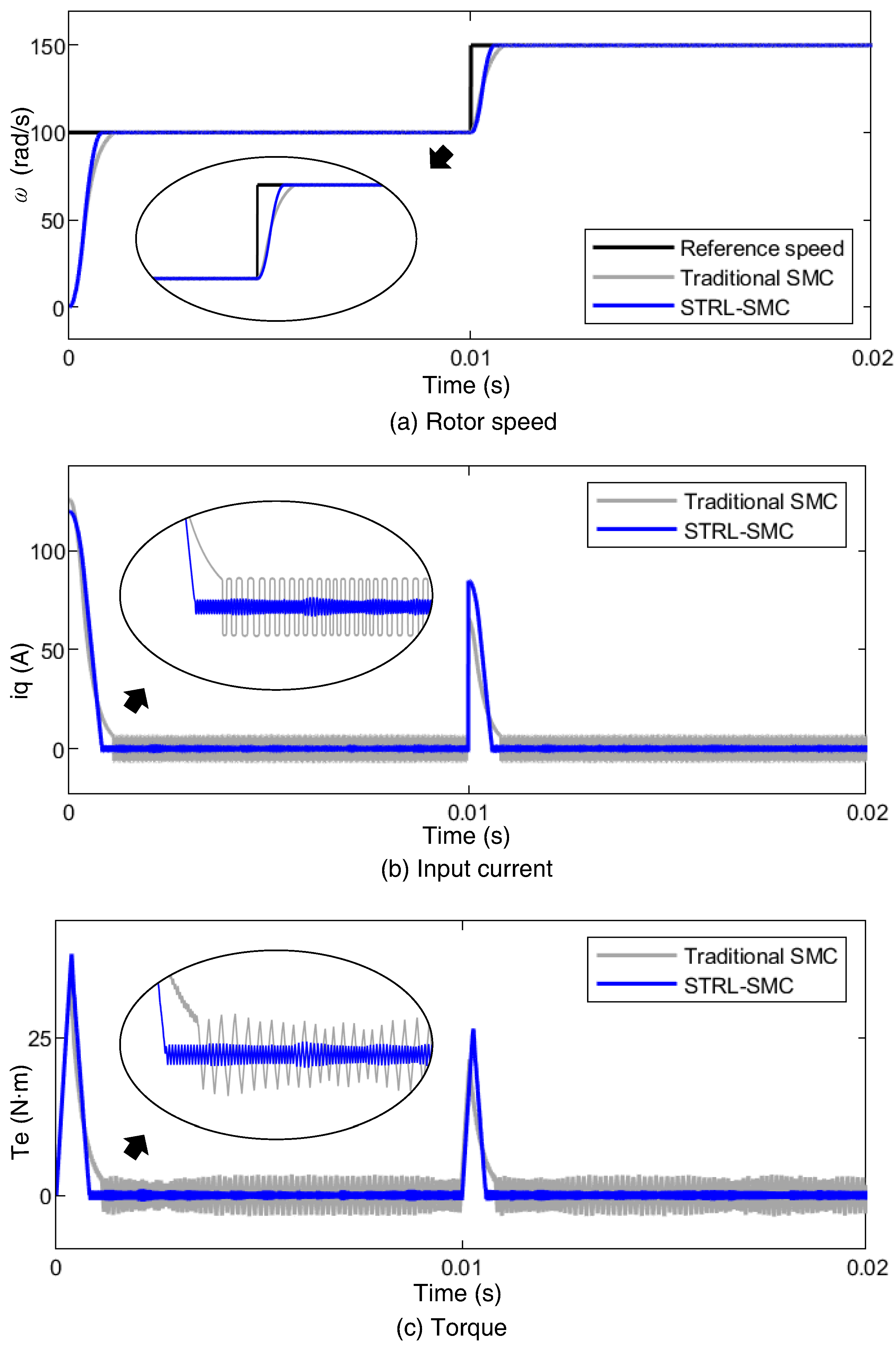
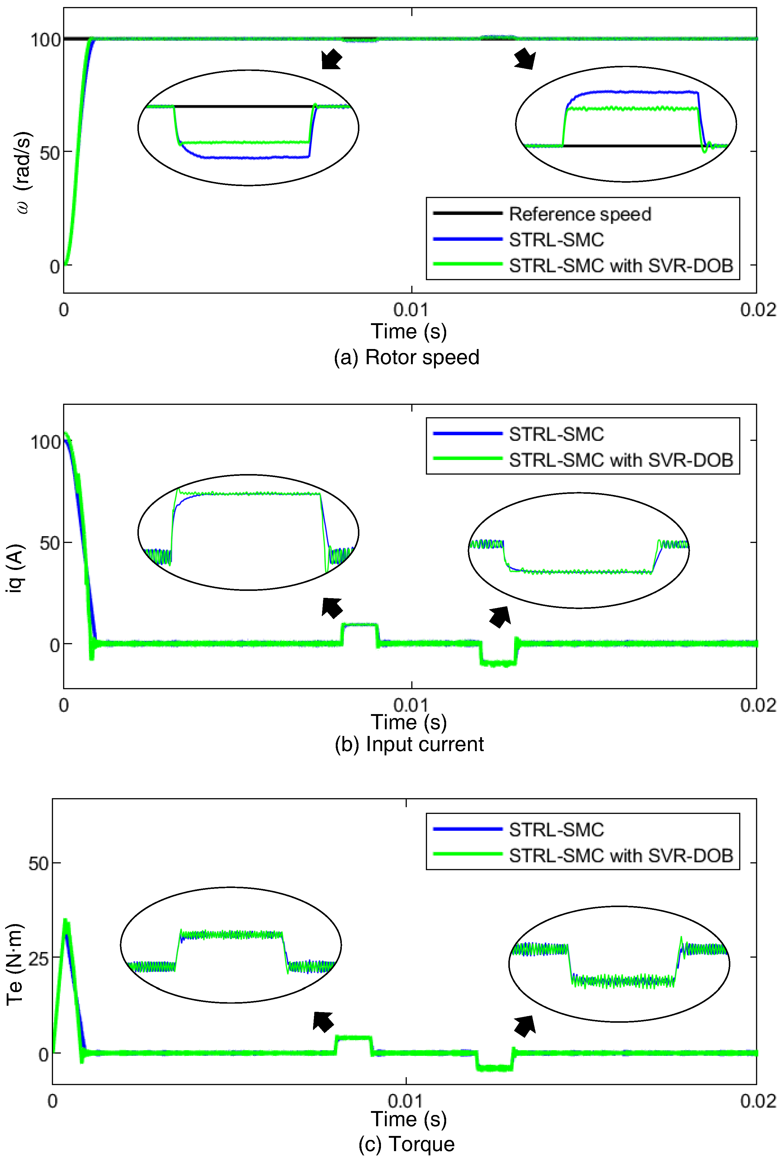
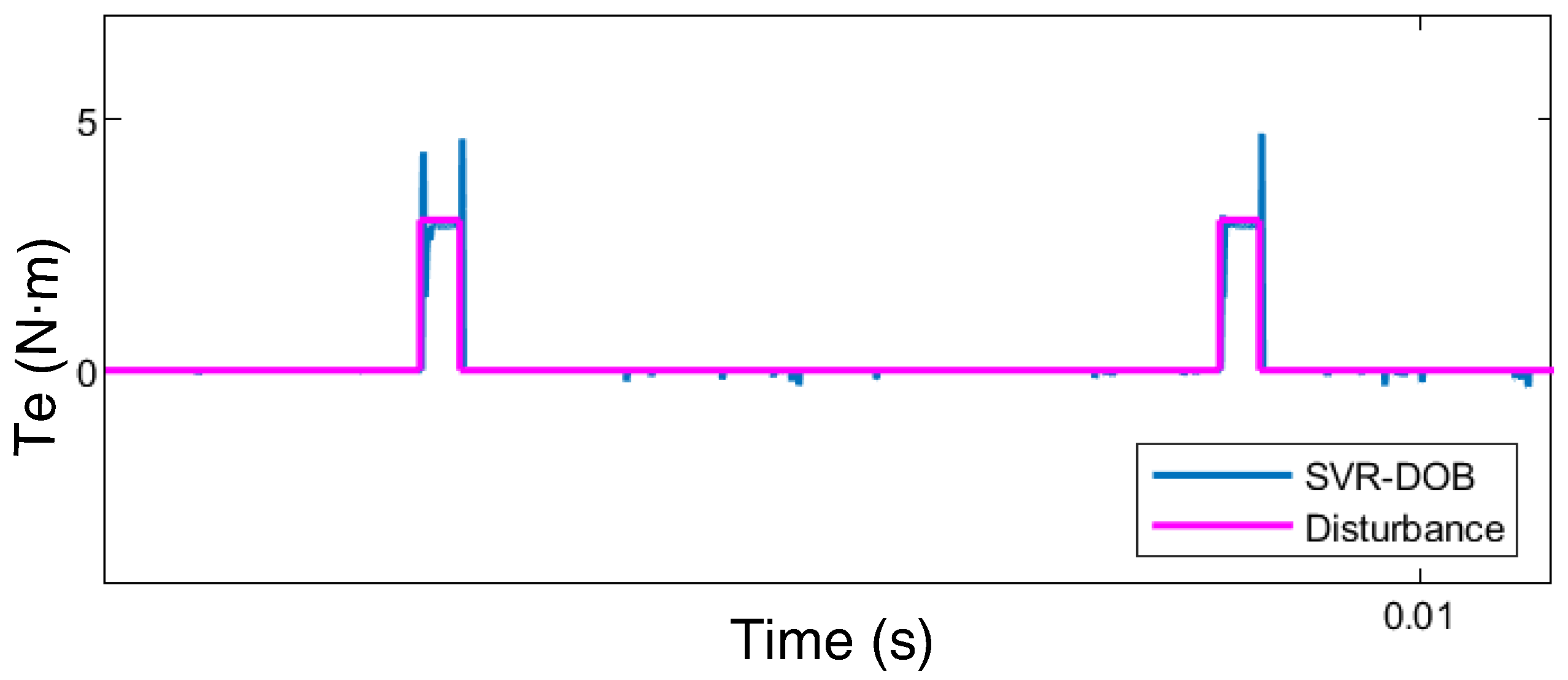
This section describes the stability of the proposed STRL-SMC method. We chose the Lyapunov function, as shown in Equation (18):
V = 1 2 s T s + 1 2 γ W T W .
where W represents the weight vector of SVR-DOB as [ w 1 , w 2 , w M ] T . The time derivative of Equation (18) can be obtained as follows:
V ˙ = s T b i q * d t + 1 γ W T W ˙ .
Substituting Equation (17) into Equation (19), Equation (20) can be written as follows:
V ˙ = s T k 1 s 1 2 sgn s k 2 0 t sgn ( s ) d τ + r ˜ + W T s T x 1 γ W ^ ˙ .
In addition, the adaptive control law can be designed as Equation (20).
W ˙ = W ^ ˙ , W ^ ˙ = γ s T x i ,
where γ is a positive constant. Using Equation (21), the Equation (22) can be derived as follows:
V ˙ = s T k 1 s 1 2 sgn s k 2 0 t sgn ( s ) d τ + 0 t r ˜ ˙ d τ ,
where k 2 r ˜ ˙ . Therefore, it is proved through Equation (23) that the time derivative of Equation (18) is less than 0.
V ˙ = s T k 1 s 1 2 sgn s k 2 0 t sgn ( s ) d τ + r ˜ s T k 1 s 1 2 sgn s 0
Thus, the stability of speed loop with disturbance can be guaranteed via Equation (18) to Equation (23).

4. Simulation

The simulation of PMSM speed control system was conducted using MATLAB/Simulink. The PMSM simulation parameters are listed in Table 1. A traditional sliding mode controller, STRL-SMC and STRL-SMC with SVR-DOB were compared to the performance. In this simulation, we designed the reaching law of traditional SMC as k 1 sgn s k 2 s [29]. With the discontinuous control input, we confirmed that there was chattering in proportion to the gain k 1 . The proposed STRL induces continuous control input which has the ability of the chattering reduction. Compared with the traditional SMC, STRL-SMC with SVR-DOB shows the reduced chattering effect as shown in Figure 3b.
The reference speed changes following the staircase waveform. Figure 3 shows the results of the traditional SMC and STRL-SMC. Moreover, quantitative results on performance index were compared in Table 2. Table 2 represents the performance difference between traditional SMC and STRL-SMC for maximum overshoot, settling time, and steady-state error according to the results in Figure 3. A comparison between traditional SMC and STRL-SMC for the speed tracking results is shown in Figure 4. The reference speed was set to 100 rad/s. The load torque was suddenly increased by 3 N · m at 0.01 s.
Figure 5 depicts the performance comparison between the traditional SMC and STRL-SMC. The gains of traditional SMC and STRL-SMC are optimized for the best performance, respectively. The load torque was suddenly increased by 3 N · m at 0.008 s and decreased by 1 N · m at 0.012 s, respectively. As shown in Figure 5, the chattering of the proposed STRL-SMC result is smaller than the traditional SMC result under the same simulation condition. The performance of SVR-DOB is represented in Figure 6.
In the Figure 4, STRL-SMC shows rapid response to track the reference speed than the traditional SMC. For transient state driven by speed increment of 50 rad/s, STRL-SMC shows better performance than the traditional SMC with a fast response. The result proves the anti-disturbance ability of STRL-SMC. The difference from the simulation results of the two control methods demonstrated smaller speed fluctuations from STRL-SMC with SVR-DOB than those from STRL-SMC. Compared with STRL-SMC, which does not include SVR-DOB, STRL-SMC with SVR-DOB exhibits a better performance and robustness to disturbances. Therefore, the STRL method has the advantages of an improved dynamic performance and disturbance rejection properties compared with traditional SMC. The proposed controller can lead the measurement speed to track successfully the reference speed of 100 rad/s.

5. Conclusions

This study introduced a robust control system for a PMSM with sliding mode control using a super-twisting reaching law and SVR-DOB. The control law suppressed the chattering and improved the disturbance observer. The PMSM speed control system with the proposed reaching law exhibits a better performance than the conventional reaching law; therefore the designed sliding mode speed controller can replace the traditional SMC regulator. An additional term for the disturbance compensation ensures the robustness of the speed controller which was applied to improve the tracking performance. A comparison of the simulation results shows the validity and effectiveness of the proposed reaching law, demonstrating that the STRL-SMC with SVR-DOB is an effective control method. Compared with the traditional SMC controller, STRL-SMC with SVR-DOB performed better in terms of speed tracking and disturbance rejection. SVR-DOB enables SMC to suppress disturbance without the data of system modeling. SVR-DOB can be trained using data of relation between current and rotor speed error. The output of SVR-DOB includes system uncertainty and compensates the disturbance effectively. SVR-DOB estimates the disturbance and model uncertainty that exist in real condition. The proposed controller has the potential to be expanded using appropriate estimators for the control of electrical machines. Using the simulation processed in this study, the experimental results in progress with PMSM hardware will be supplemented in future work. The proposed controller has the potential to be applied to PMSM and can show improved performance. The disturbance estimation of SVR-DOB can improve the performance of the proposed controller in real industrial applications.

Author Contributions

This research was accomplished by all the authors. A.C. and K.Y. conceived the idea, performed the analysis, and designed the simulation; A.C., H.K. and M.H. conducted the numerical simulations; and H.K., H.A. and Y.K. co-wrote the manuscript. All authors have read and agreed to the published version of the manuscript.

Funding

This work was supported by the National Research Foundation of Korea (NRF) grant funded by the Korea government (MSIP) (NRF-2019R1A2C1002343) and the BK21 FOUR Project.

Institutional Review Board Statement

Not applicable.

Informed Consent Statement

Not applicable.

Data Availability Statement

Data sharing not applicable.

Conflicts of Interest

The authors declare no conflict of interest.

References

  1. Zhao, K.; Li, P.; Zhang, C.; Li, X.; He, J.; Lin, Y. Sliding mode observer-based current sensor fault reconstruction and unknown load disturbance estimation for PMSM driven system. Sensors 2017, 17, 2833. [Google Scholar] [CrossRef] [PubMed] [Green Version]
  2. Shi, Z.; Sun, X.; Cai, Y.; Yang, Z.; Lei, G.; Guo, Y.; Zhu, J. Torque analysis and dynamic performance improvement of a PMSM for EVs by skew angle optimization. IEEE Trans. Appl. Supercond. 2019, 29, 1–5. [Google Scholar] [CrossRef]
  3. Jung, J.W.; Leu, V.Q.; Do, T.D.; Kim, E.K.; Choi, H.H. Adaptive PID speed control design for permanent magnet synchronous motor drives. IEEE Trans. Power Electron. 2014, 30, 900–908. [Google Scholar] [CrossRef]
  4. Xiaoguang, Z.; Ke, Z.; Li, S. A PMSM sliding mode control system based on a novel reaching law. In Proceedings of the 2011 International Conference on Electrical Machines and Systems, Beijing, China, 20–23 August 2011; pp. 1–5. [Google Scholar] [CrossRef]
  5. Ali, N.; Ur Rehman, A.; Alam, W.; Maqsood, H. Disturbance observer based robust sliding mode control of permanent magnet synchronous motor. J. Electr. Eng. Technol. 2019, 14, 2531–2538. [Google Scholar] [CrossRef]
  6. Zhang, X.; Sun, L.; Zhao, K.; Sun, L. Nonlinear speed control for PMSM system using sliding-mode control and disturbance compensation techniques. IEEE Trans. Power Electron. 2013, 28, 1358–1365. [Google Scholar] [CrossRef]
  7. Wang, H.; Li, S.; Lan, Q.; Zhao, Z.; Zhou, X. Continuous terminal sliding mode control with extended state observer for PMSM speed regulation system. Trans. Inst. Meas. Control 2017, 39, 1195–1204. [Google Scholar] [CrossRef]
  8. Hou, H.; Yu, X.; Xu, L.; Rsetam, K.; Cao, Z. Finite-time continuous terminal sliding mode control of servo motor systems. IEEE Trans. Ind. Electron. 2020, 67, 5647–5656. [Google Scholar] [CrossRef]
  9. Ding, S.; Park, J.H.; Chen, C.C. Second-order sliding mode controller design with output constraint. Automatica 2020, 112, 108704. [Google Scholar] [CrossRef]
  10. Fortuna, L.; Muscato, G. A roll stabilization system for a monohull ship: Modeling, identification, and adaptive control. IEEE Trans. Control Syst. Technol. 1996, 4, 18–28. [Google Scholar] [CrossRef]
  11. Chu, V.K.; Tomizuka, M. Sliding mode control with nonlinear sliding surfaces. IFAC Proc. Vol. 1996, 29, 2877–2882. [Google Scholar] [CrossRef]
  12. Qiao, L.; Zhang, W. Adaptive second-order fast nonsingular terminal sliding mode tracking control for fully actuated autonomous underwater vehicles. IEEE J. Ocean. Eng. 2018, 44, 363–385. [Google Scholar] [CrossRef]
  13. Li, S.; Zhou, M.; Yu, X. Design and implementation of terminal sliding mode control method for PMSM speed regulation system. IEEE Trans. Ind. Inf. 2013, 9, 1879–1891. [Google Scholar] [CrossRef]
  14. Hou, Q.; Ding, S.; Yu, X. Composite super-twisting sliding mode control design for PMSM speed regulation problem based on a novel disturbance observer. IEEE Trans. Energy Convers. 2020, 36, 2591–2599. [Google Scholar] [CrossRef]
  15. Xu, W.; Jiang, Y.; Mu, C. Novel composite sliding mode control for PMSM drive system based on disturbance observer. IEEE Trans. Appl. Supercond. 2016, 26, 1–5. [Google Scholar] [CrossRef]
  16. Kim, E.; Kim, J.; Nguyen, H.T.; Choi, H.H.; Jung, J.W. Compensation of parameter uncertainty using an adaptive sliding mode control strategy for an interior permanent magnet synchronous motor drive. IEEE Access 2019, 7, 11913–11923. [Google Scholar] [CrossRef]
  17. Liu, Y.; Zhou, B.; Fang, S. Sliding mode control of PMSM based on a novel disturbance observer. In Proceedings of the 2009 4th IEEE Conference on Industrial Electronics and Applications, Xi’an, China, 25–27 May 2009; pp. 1990–1994. [Google Scholar] [CrossRef]
  18. Sun, X.; Cao, J.; Lei, G.; Guo, Y.; Zhu, J. A composite sliding mode control for SPMSM drives based on a new hybrid reaching law with disturbance compensation. IEEE Trans. Transp. Electrif. 2021, 7, 1427–1436. [Google Scholar] [CrossRef]
  19. Wang, Y.; Feng, Y.; Zhang, X.; Liang, J. A new reaching law for antidisturbance sliding-mode control of PMSM speed regulation system. IEEE Trans. Power Electron. 2019, 35, 4117–4126. [Google Scholar] [CrossRef]
  20. Burton, J.A.; Zinober, A.S.I. Continuous approximation of variable structure control. Int. J. Syst. Sci. 1986, 17, 875–885. [Google Scholar] [CrossRef]
  21. Cruz-Zavala, E.; Moreno, J.A.; Fridman, L.M. Adaptive gains super-twisting algorithm for systems with growing perturbations. IFAC Proc. Vol. 2011, 44, 3039–3044. [Google Scholar] [CrossRef]
  22. Hou, Q.; Ding, S. GPIO based super-twisting sliding mode control for PMSM. IEEE Trans. Circuits Syst. II Express Briefs 2020, 68, 747–751. [Google Scholar] [CrossRef]
  23. Weijie, L.; Dongliang, L.; Qiuxuan, W.; Xiaodan, Z. On sliding mode control of permanent magnet synchronous motor. In Proceedings of the The 26th Chinese Control and Decision Conference (2014 CCDC), Changsha, China, 31 May–2 June 2014; pp. 4555–4559. [Google Scholar] [CrossRef]
  24. Shtessel, Y.; Taleb, M.; Plestan, F. A novel adaptive-gain supertwisting sliding mode controller: Methodology and application. Automatica 2012, 48, 759–769. [Google Scholar] [CrossRef]
  25. Zhang, L.; Bai, J.; Wu, J. SPMSM sliding mode control based on the new super twisting algorithm. Complexity 2021, 2021, 2886789. [Google Scholar] [CrossRef]
  26. Moreno, J.A.; Osorio, M. A Lyapunov approach to second-order sliding mode controllers and observers. In Proceedings of the 2008 47th IEEE Conference on Decision and Control, Cancun, Mexico, 9–11 December 2008; pp. 2856–2861. [Google Scholar]
  27. Moreno, J.A.; Osorio, M. Strict Lyapunov functions for the super-twisting algorithm. IEEE Trans. Automat. Contr. 2012, 57, 1035–1040. [Google Scholar] [CrossRef]
  28. Uçak, K.; Öke Günel, G. An adaptive sliding mode controller based on online support vector regression for nonlinear systems. Soft Comput. 2020, 24, 4623–4643. [Google Scholar] [CrossRef]
  29. Xu, C.; Wang, K.; Wang, Y.; Chen, C.; Zhang, B. Super-twisting sliding mode control of permanent magnet synchronous motor based on predictive adaptive law. In Proceedings of the 2021 IEEE 5th Advanced Information Technology, Electronic and Automation Control Conference (IAEAC), Chongqing, China, 12–14 March 2021; Volume 5, pp. 2731–2736. [Google Scholar] [CrossRef]
Figure 1. SMC with SVR-DOB of a PMSM.
Applsci 12 10749 g001
Figure 2. Example of support vector regression.
Applsci 12 10749 g002
Figure 3. Comparison between traditional SMC and STRL-SMC for disturbance suppression.
Applsci 12 10749 g003
Figure 4. Rotor speed comparison between traditional SMC and STRL-SMC for speed tracking.
Applsci 12 10749 g004
Figure 5. Comparison between STRL-SMC and STRL-SMC with SVR-DOB.
Applsci 12 10749 g005
Figure 6. Disturbance estimation of SVR-DOB.
Applsci 12 10749 g006
Table 1. Parameters of PMSM.
SymbolParameterValue
RStator phase resistance2.875 Ω
LInductance153 mH
ψ f Flux linkage0.175 Wb
JInertia5.5 × 10−3 kg·m 2
n p Pole pairs4
Table 2. Performance index comparison between traditional SMC and STRL-SMC.
Traditional SMCSTRL-SMC
Maximum overshoot (rad/s)2.9262.284
Settling time (s)0.001430.00140
Steady-state error (rad/s)3.4933.449
Publisher’s Note: MDPI stays neutral with regard to jurisdictional claims in published maps and institutional affiliations.

