Article

Study on the Shearer Attitude Sensing Error Compensation Method Based on Strapdown Inertial Navigation System

Research Center of Intelligent Mining, School of Mines, China University of Mining & Technology, Xuzhou 221116, China
*
Author to whom correspondence should be addressed.
Appl. Sci. 2022, 12(21), 10848; https://doi.org/10.3390/app122110848
Submission received: 20 August 2022 / Revised: 16 October 2022 / Accepted: 21 October 2022 / Published: 26 October 2022
(This article belongs to the Section Mechanical Engineering)

Abstract

:
Intelligent mining is the demand and inevitable development direction of China’s coal industry, and the shearer attitude based on the 3D spatial scale is the essential basic information for realizing intelligent mining at the fully mechanized mining face. The traditional shearer attitude monitoring technology cannot meet the accuracy requirements of attitude sensing of mining equipment at an intelligent working face. In this paper, based on the basic principle of strapdown inertial navigation system (SINS), a real-time solution algorithm for shearer attitude is constructed, and the specific process of SINS coarse alignment and fine alignment is studied. The main error terms affecting the accuracy of SINS are analyzed, and the initial alignment error, installation deviation angle error, and vibration effect error are compensated and analyzed through simulation one by one. According to the working characteristics of the shearer, the coning error and sculling error of the shearer’s SINS are compensated and analyzed through simulation. This paper provides a complete set of theories and methods for improvement of the accuracy of the shearer attitude sensing in underground operation; simulation results also verify that the theories and methods can significantly improve the perception accuracy which can provide theoretical and technical reference for the production state prediction of fully mechanized mining face and intelligent control of underground mining equipment.

1. Introduction

Coal has always been the main energy source in China, accounting for more than 70% and 60% of primary energy production and consumption [1]. The world’s energy picture and the real economic and social demands determine that coal will remain the main energy source in China for a long time to come. Taking the advantage of scientific and technological progress to eliminate the drawbacks in the production and utilization of coal and realize safe and efficient green mining and clean and efficient utilization is the direction of coal development [2,3]. China has proposed the strategy of “Made in China 2025” with the development of intelligent manufacturing, intelligent equipping, and intelligent producing as its main content. Building intelligent coal mines and developing intelligent mining technology is in line with the national strategy and is an inevitable choice for the development of China’s coal industry [4]. With the intelligent mining technology, the production equipment at the coal mine working face can be remotely monitored and intelligently controlled on the ground or in the mining roadway, so the miners can move from the dangerous working face to the roadway or the ground during the mining process, reducing the occurrence of safety accidents and casualties greatly, and the production efficiency and safety level will also be significantly improved [5]. At present, intelligent mining technology and equipment have been successfully applied in some mines, but the overall level of coal mine intelligence is far from the expected effect due to the complex and variable coal seam occurrence conditions in China. A series of key technical problems during intelligent mining need to be solved urgently, including the precise positioning and navigation of the mining equipment at underground working face [6], the intelligent sensing of the mining environment information at working face [7], the adaptive control of the support system and surrounding rock, the cooperative control of the mining equipment [8], the intelligent prediction and early warning of the mining hazards on mining site, etc. [9].
It is one of the keys to realizing intelligent mining at a working face to accurately perceive the attitude of the shearer [10]. Shearer, hydraulic support, and scraper conveyor are called “three machines” at the working face. The shearer undertakes the task of cutting and loading coal at the working face. The track of the scraper conveyor provides a movement path for the shearer to perform reciprocating coal cutting. The cutting path of the bottom plate of the shearer drum determines the attitude of the scraper conveyor. The cutting path of the top plate determines the support height of the hydraulic support, and its movement track indirectly reflects the straightness bending state of the scraper conveyor. All of these production state elements of the intelligent working face can be obtained by constructing the information on position and attitude and geometric characteristics of the shearer during operation. The accurate attitude information of the shearer is the key to ensuring its automatic coal cutting and the automatic moving of hydraulic supports [11], and it is also the basis for realizing the adaptive cutting by the shearer [12]. The research on real-time and accurate shearer attitude sensing can not only provide a way to detect and predict the production state of the intelligent working face, but also supply basic information for the shearer’s independent height adjustment, coal cutting, and other intelligent decision-making to realize intelligent control.

2. State of the Art

Due to the harsh, complex, and closed underground working environment of the shearer in the coal mines, the conventional ground positioning methods such as radio navigation, satellite positioning, and astronomical navigation cannot function underground, while traditional shearer position and attitude monitoring methods such as the active infrared intrusion detector method can only measure the intermittent position instead of the dynamic position of the shearer, with complicated installation and relatively evident signal loss [13]. The gear counting method can only calculate the walking distance of the shearer, with a cumulative error existing [14]. The ultrasonic reflection method is difficult for signal acquisition, with relatively poor system scalability [15]. The wireless sensor network method is subject to a significant disturbance in the harsh environment of the coal mines, with such problems as unstable positioning data [16]. At the same time, the above methods cannot measure the shearer attitude and cannot meet the accuracy requirements of intelligent mining [17].
At the beginning of the 21st century, CSIRO started research on the automation and intelligence of the fully mechanized mining face, and designed and developed the LASC (Longwall Automation Steering Committee) system which was successfully applied to the Beltana coal mine in Australia by using military grade high precision fiber optic gyroscopes and navigation algorithms to realize the positioning of shearer and the automatic straightening of the scraper conveyor. In 2008, the LASC system was upgraded in technology. Combining the detailed geological data and the 3D model of the mining space, the position monitoring of the working face production equipment, the memory cutting of the shearer, and the 3D visualization of the mining space were realized [18]. JOY has developed Faceboss and advanced shearer automation (ASA) for intelligent shearers, which can realize automatic traction, horizontal control, Golp offline graphics editing, automatic triangular coal mining and automatic integration of working faces, and install traction encoder, inclination sensor, D gear sensor, fuselage pitch/tilt sensor, etc. on the shearer (the pitch/tilt sensor is used as a backup supplement of INS) through these sensors monitoring the attitude, position, and mining height [19]. Eickhoff shearer automation technology has mainly gone through four stages: memory cutting, EiControl, EiControlSB, EiControlPlus. The shearer supplied with the EiControlPlus system is equipped with vibration sensors, position sensors, travel sensors, infrared sensors, inclination sensors and radar sensors, etc. A variety of sensors can realize real-time monitoring of the position and attitude of the shearer on the basis of redundancy [20]. At present, the SINS is still lacking in adaptability, error modeling and compensation under temperature and vibration disturbances [21].
For the purpose of achieving accurate shearer attitude sensing, this paper, on the basis of the research on intelligent mining technology, deeply studies SINS error compensation using the shearer attitude sensing method based on SINS to improve the shearer attitude measurement and sensing accuracy in an underground coal mine. The results of this paper will provide research foundation and technical reference for the prediction of production state and the intelligent control of shearer at fully mechanized mining face.

3. Principle of the Shearer Attitude Sensing System

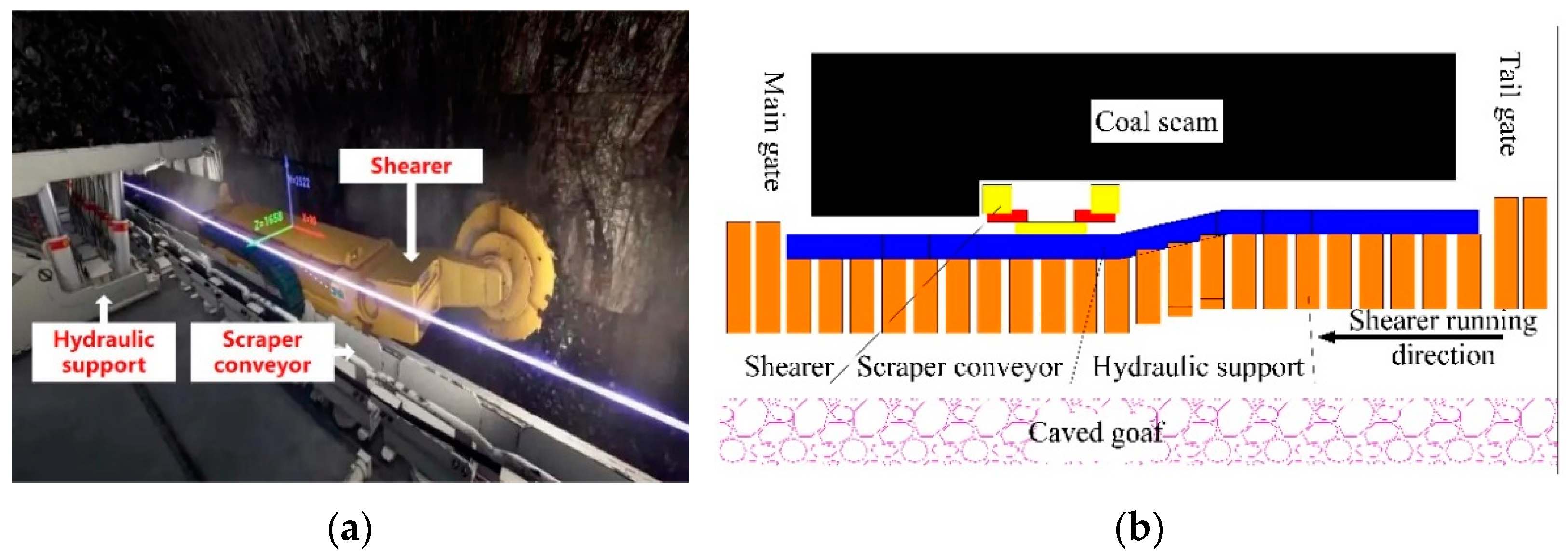
3.1. Motion Characteristics of the Shearer

The shearer is the core equipment for coal cutting and loading at the mine working face. During the mining process, the shearer takes the scraper conveyor as the carrier to realize the process of reciprocating coal-cutting operation, and the mined coal is transported to the reloader by the scraper conveyor, and then delivered to the haulage roadway by a conveyor belt. The hydraulic supports hold up the roof and isolate the goaf to provide sufficient working space for the shearer and scraper conveyor. The equipment layout of a fully mechanized mining face is shown in Figure 1. When working, the shearer not only reciprocates on the scraper conveyor and moves in the direction of the scraper conveyor nudging, but also changes its height with the undulation of the coal seam floor. It is also affected by the coal seam dip angle and cutter feeding way for coal cutting, resulting in the change of the shearer attitude. Therefore, the shearer position and attitude are in three-dimensional change during its working, and only acquiring the information on the shearer attitude in real time can ensure smooth mining at the working face.

3.2. Principle of the Shearer Attitude Sensing System

SINS is a navigation system in which inertial sensors (including such sensors as accelerometers and gyroscopes) are directly fixed onto a running carrier, and the acceleration and the angular velocity of the carrier are measured by the accelerometers and gyroscopes, respectively. The initial position, velocity, acceleration, and angular velocity of the carrier are used together to obtain various navigation parameters such as position, velocity, and running attitude of the running carrier through integration calculation [22]. The SINS is applied onto a shearer to sense its attitude. In fact, the acceleration and angular velocity of the shearer relative to the inertial space are measured with the accelerometer and gyroscope and then the attitude information of the shearer is obtained through iterative calculation [23]. In other words, the three-dimensional coordinates and motion parameters of the shearer in a coordinate system at a time point are determined. This process is realized in the carrier coordinate system (b system) and cannot be directly used to solve for the shearer attitude [24] as the shearer attitude needs to be solved for in the navigation coordinate system (n system). Accordingly, when the shearer attitude is solved for, transformation between the carrier coordinate system and the navigation coordinate system is needed [25]. The orientation relationship between the above two coordinate systems is shown in Figure 2, and it gives the attitude angles of the shearer, including heading angle, pitch angle, and roll angle, which are φ, θ, and γ, respectively.
It is defined that the transformation between the n system and the b system is realized through three single-axis rotations, of which the order is as follows:
O X n Y n Z n Around   Z n   axis Rotate   by   φ O X 1 Y 1 Z 1 Around   X 1   axis Rotate   by   θ O X 2 Y 2 Z 2 Around   Y 2   axis Rotate   by   γ O X b Y b Z b .
Then, the transformation matrix from the b system to the n system is
C n b = C γ C θ C φ = ( cos γ 0 sin γ 0 1 0 sin γ 0 cos γ ) ( 1 0 0 0 cos θ sin θ 0 sin θ cos θ ) ( cos φ sin φ 0 sin φ cos φ 0 0 0 1 ) =
( cos γ cos φ + sin γ sin θ sin φ cos γ sin φ + sin γ sin θ cos φ sin γ cos θ sin φ cos θ cos φ cos θ sin θ sin γ cos φ cos γ sin φ sin θ sin γ sin φ cos γ sin φ cos θ cos γ cos θ ) .
The matrix C n b is evidently an orthogonal matrix; then
C b n = ( C n b ) T = ( cos γ cos φ + sin γ sin θ sin φ sin φ cos θ sin γ cos φ cos γ sin φ sin θ cos γ sin φ + sin γ sin θ cos φ cos φ cos θ sin γ sin φ cos γ sin φ cos θ sin γ cos θ sin θ cos γ cos θ ) .
Matrix C n b is called an attitude matrix or a strapdown matrix.
The information on the shearer attitude angle can be obtained by solving the attitude matrix, and the acceleration measured by the accelerometer is also to be solved for velocity and position with the attitude matrix. So far, the principle of the shearer attitude sensing system based on SINS can be expressed with Figure 3.

3.3. Calculating Algorithm of the Shearer Attitude

For SINS, the attitude quaternion or attitude matrix of the b system relative to the n system is commonly used to represent the attitude. The relative position change rate between the n system and the earth coordinate system (e system) is commonly used to express the velocity. The position matrix of the n system relative to the e system and the distance of SINS relative to the earth’s horizontal line are commonly used to represent the position [26].
The quaternion differential equation for attitude update:
Q b n = 1 2 Q b n ( ω i b b ) q 1 2 ( ω i n n ) q Q b n .
The differential equation for velocity update:
V n = C b n f b ( 2 ω i e n + ω e n n ) V n + g n .
The differential equation for position update:
[ L λ h ] = [ v y R M + h v x ( R N + h ) cos L v z ] ,
where Q b n is the shearer attitude quaternion; ω i b b is the output angular velocity of a gyroscope; ω i e n is the rotational angular velocity of the earth; V n is the velocity of the shearer; ω e n n is the rotational angular velocity caused by V n ; ω i n n = ω i e n + ω e n n ; f b is the specific force outputted by accelerometer; g n is the acceleration of gravity at the position of the shearer; L is the latitude of the shearer; λ is the longitude of the shearer; h is the height of the shearer; vx, vy, vz are the components of the shearer in east, north, and sky directions, respectively.
The shearer attitude angle is obtained by solving Equation (3), and the shearer velocity and position are obtained by integrating Equation (5) once and twice, respectively. The shearer attitude can be obtained in real time by combining the velocity and position with the attitude angle information.

4. Error Sources of SINS

SINS has advantages of small volume, light weight, high sensing accuracy, high reliability, and good real-time performance, but its basic principle and solution process determines that it is difficult to effectively correct the accumulated errors at long endurance. If there is an error in the output value of the inertial sensor at a time point, this error will continue to exist in the subsequent calculation process, so that the error in the inertial navigation system accumulates constantly over time, and eventually the accuracy of the shearer attitude sensing will be significantly reduced. Therefore, it is necessary to make effective compensation for the various errors from SINS. The errors affecting the SINS accuracy mainly include initial alignment error, installation error, measurement error by the inertial sensor, calculation error, etc.
(1)
Initial alignment error
If no effective error elimination is performed during the initial alignment process, the typical values of various initial alignment errors will be superimposed onto the final attitude, velocity, and position parameters at the beginning of navigation, thus affecting the output value of the navigation system.
(2)
Installation error
Installation errors include installation deviation angle error and lever arm effect error. In the SINS of the shearer, the installation deviation angle error means that there is an included angle between the sensing axis of the inertial navigation assembly and the coordinate axis of the shearer body due to the installation process and the working state of the shearer, causing the output of the inertial sensor not to be the real navigation parameter of the shearer. The lever arm effect error means that the non-coincidence of the mass center of the inertial navigation assembly and that of the shearer body causes an interference acceleration, which affects the output value of the accelerometer and thus influences the shearer positioning accuracy.
(3)
Inertia sensor error
The inertial sensor error refers to the errors caused by gyroscopes and accelerometers themselves, mainly including accuracy error, zero bias error, scale factor error, random noise error, etc. These errors are mainly determined by the processing technology and assembly level of the sensor itself.
(4)
Calculation error
It includes the solution algorithm approximation error, computer algorithm error, processor calculation error, etc. [27], and it is basically negligible.
It has been proved through long-term theoretical studies and numerous practice operations that the errors affecting the accuracy of the SINS are mainly the initial alignment error, installation error, and inertial sensor error [28]. The influence of the inertial sensor error on the shearer attitude sensing is not discussed in this paper.

5. Initial Alignment Error Compensation for Shearer’s SINS

As the initial alignment error of SINS will gradually accumulate in the subsequent navigation solution, it is necessary to reduce the initial alignment error as much as possible, especially to strictly restrain the initial attitude error. In addition, the alignment time should be as short as possible. The system can complete alignment in a short time after start-up, reducing the response waiting time, which can effectively improve the shearer operating rate and facilitate the personnel and various devices at the working face and the process coordination among the personnel and devices. In the following section, the initial alignment error of the shearer will be suppressed based on its attitude sensing requirements and the onsite characteristics of the working face.

5.1. Initial Alignment of SINS

Initial alignment refers to the determination of the attitude angle, position, and velocity of the carrier at the initial time point. The initial alignment process includes two stages, i.e., coarse alignment and fine alignment. The coarse alignment stage is to calculate the initial attitude matrix of the system directly using the output information of the gyroscope and accelerometer, and this alignment stage is not accurate enough and ignores the influences of such factors as the possible vibration of the carrier itself and temperature change, so this stage only provides the initial attitude matrix that meets the requirements of the next fine alignment stage. The fine alignment stage occurs after the coarse alignment stage, and the inertial sensor is generally required to be in a stationary state to estimate the attitude error angle of the system. After the inertial sensor reaches a stable working state, the initial attitude matrix of the system is corrected to finally complete the fine alignment stage. The specific process is as follows:
The initial outputs of the accelerometer and gyroscope in the b system are
{ g 0 = ( a x 0 , a y 0 , a z 0 ) T ω 0 = ( a x 0 , a y 0 , a z 0 ) T .
According to the transformation relationship between the b system and the n system, we can obtain
( a x 0 a y 0 a z 0 ω x 0 ω y 0 ω z 0 B x 0 B y 0 B z 0 ) = ( 0 0 g 0 ω i e cos L ω i e sin L ω i e g cos L 0 0 ) C 0 n ,
that is
C 0 n = ( 0 0 1 ω i e g cos L sin L g cos L 1 ω i e cos L 0 1 g 0 0 ) ( a x 0 a y 0 a z 0 ω x 0 ω y 0 ω z 0 B x 0 B y 0 B z 0 ) .
C 0 n is the coarse alignment attitude matrix, and then it is corrected with the error model in the next step to complete the fine alignment stage.
A transition navigation coordinate system is obtained by transforming the carrier coordinates with C 0 n . Assuming that there is a small attitude error angle between the transition navigation coordinate system and the n system, the antisymmetric matrix C 0 n of the attitude error angle between the transition navigation coordinate system and the n system is
C 0 n = C n n C 0 n ,
where
C n n = ( 1 φ z φ y φ z 1 φ x φ y φ x 1 ) ,
where φx, φy, and φz are the attitude error angles between the transition navigation coordinate system and the n system, so it is necessary to solve C n n to correct C 0 n , and then an accurate initial attitude matrix C 0 n can be obtained.
Let the change in velocity in one solving cycle be Δ v n and the change in angle be Δ θ n , then
{ Δ v n = ( 0 , 0 , g t 0 ) T Δ θ n = ( 0 , ω i e cos L t 0 , ω i e sin L t 0 ) T .
For accelerometer and gyroscope outputs, it follows that
{ Δ v 0 = C n 0 Δ v n + Δ v r 0 Δ θ 0 = C n 0 Δ θ n + Δ θ r 0 .
The velocity increment error and angle increment error thus can be obtained as follows:
{ δ v n = C 0 n Δ v 0 Δ v n δ θ n = C 0 n Δ θ 0 Δ θ n .
Since C n n = ( C n n ) T , it gives
( φ x φ y φ z ) = ( δ v y n + C 0 n Δ v r 0 g t 0 δ v x n + C 0 n Δ v r 0 g t 0 δ θ x n + t 0 φ y ω i e sin L C 0 n Δ θ r 0 t 0 ω i e cos L ) = ( δ v y n g t 0 + Δ φ x r δ v x n g t 0 + Δ φ y r φ y ω i e sin L + ω x ω i e cos L + Δ φ z r ) .
The real-time estimation of φx, φy, and φz is completed by Equation (14), and the estimates are substituted into Equation (10) to yield an accurate initial attitude matrix, thus obtaining the accurate initial attitude angle of the shearer.
For the shearer’s SINS, the alignment time should be as short as possible. The system can complete alignment in a short time after start-up, reducing the response waiting time, which can effectively improve the shearer operating rate and facilitate the personnel and various devices at the working face and the process coordination among the personnel and devices. In the following section, the initial alignment error of the shearer will be suppressed based on its attitude sensing requirements and the onsite characteristics of the working face.

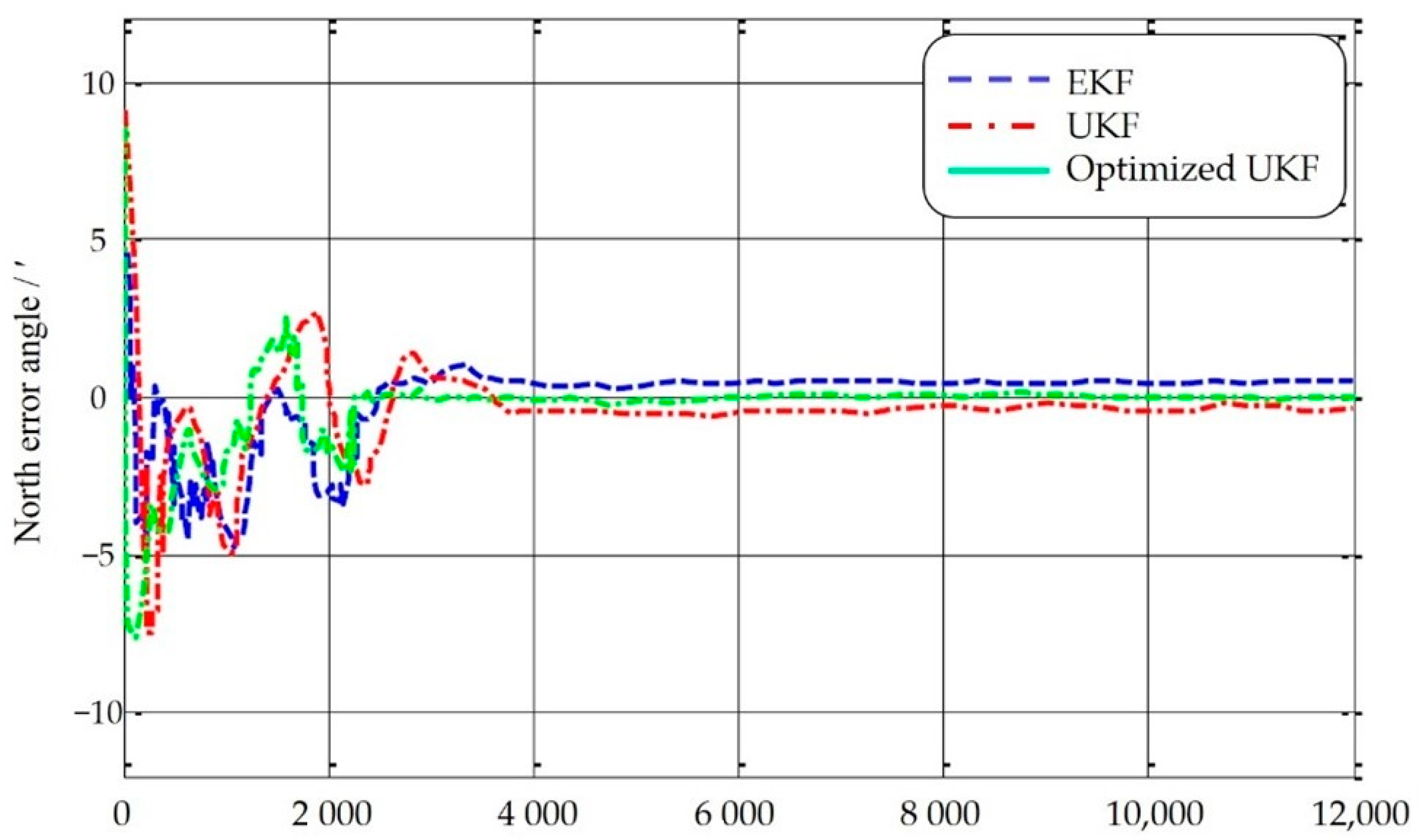
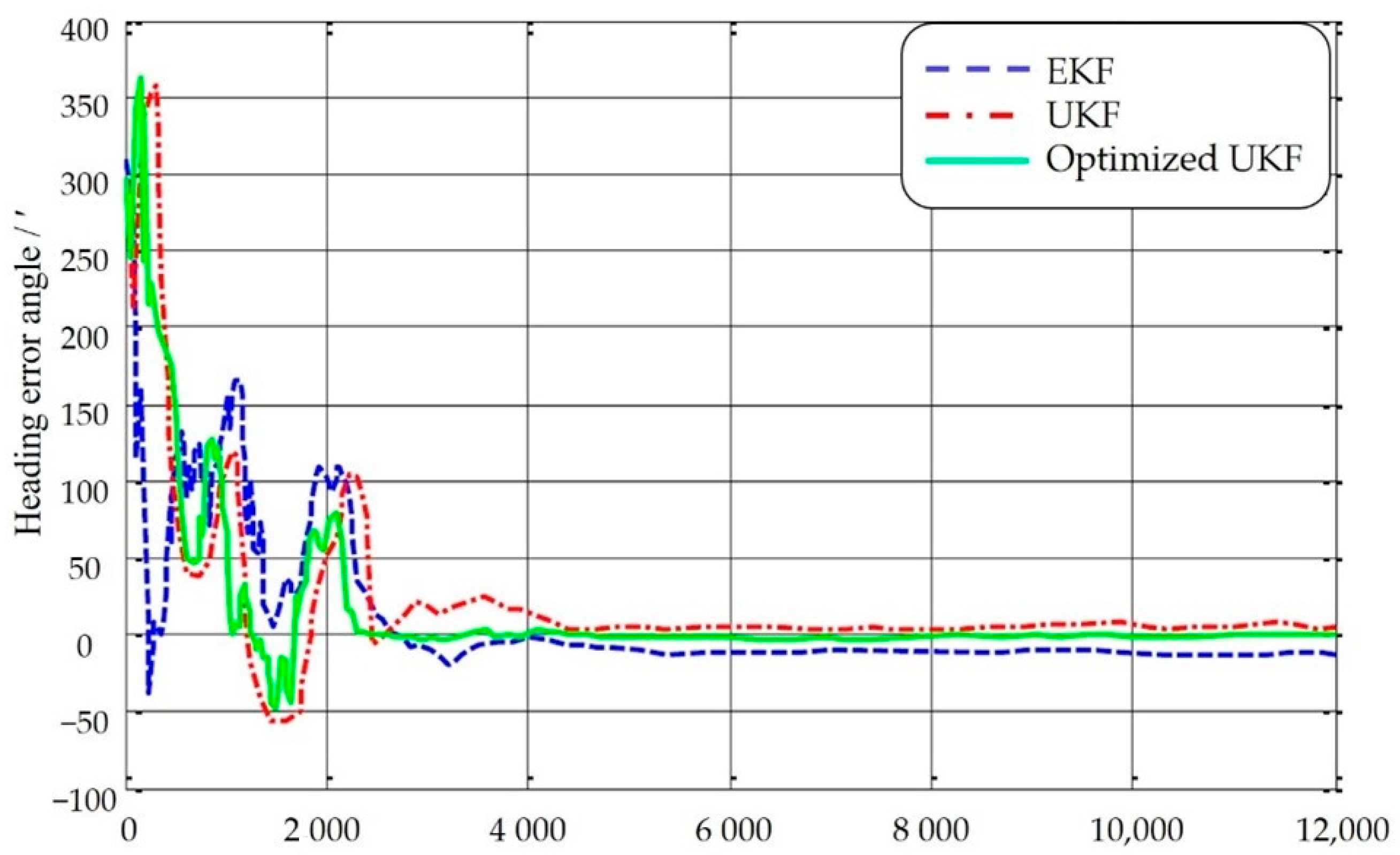
5.2. Fine Alignment Stage Based on Optimized UKF Algorithm

For SINS, the Kalman filter algorithm is often used to suppress its initial alignment error, but SINS often exhibits different degrees of nonlinearity, and the Kalman filter (KF) algorithm is not good enough to suppress the error of nonlinear systems. Therefore, based on the research of the Kalman filter algorithm, a nonlinear Kalman filter algorithm, namely unscented Kalman filter (UKF) algorithm, is proposed, in which unscented transform (UT transform) is used to determine the sampling point near the estimation point, and the Kalman linear filter framework is used to avoid the degradation defect of particle filter generated by random sampling. Studies show that the filter performance of UKF is much better than that of KF with comparable computational effort. Under the actual conditions, the computational effort and complexity of UKF are much lower than that of the particle filter. In the following section, the UKF optimization algorithm is used to compensate for the fine alignment stage of the initial alignment [29].
We are assuming that after the initial coarse alignment, the error angles φE, φN, and φU are all small angles. The horizontal error angle is smaller than the orientation error angle in the shearer’s SINS, so the influences of the horizontal cross-coupling terms φ N ω i e sin L , φ E ω i e cos L , and φ E ω i e sin L can be omitted. While in the fine alignment, the position is known, so the influences of δ L ω i e cos L and δ L ω i e sin L can be omitted. Under these conditions, the error equation related to the initial fine alignment can be obtained as follows:
δ V · E = 2 ω i e sin L δ V N φ N g + ε a x δ V · N = 2 ω i e sin L δ V E φ E g + ε a y φ · E = φ N ω i e sin L φ U ω i e cos L + ε ω x φ · N = φ E ω i e sin L + ε ω y φ · U = φ E ω i e cos L + ε ω z
Due to the short time of initial alignment, the gyroscope drift and the accelerometer zero offset can be considered as random constants, then
ε · w = 0 , ε · a = 0 .
Therefore, the SINS can be expressed as follows:
[ ε a E   ε a N   ε a U ] T = C b n [ ε a x   ε a y   ε a z ] T
[ ε w E   ε w N   ε w U ] T = C b n [ ε w x   ε w y   ε w z ] T
Based on the model of the inertial sensor, the error state equation of the SINS alignment is expressed as follows:
X · = A X + W .
In the equation, X = [ δ V E   δ V N   φ E   φ N   φ U   ε a x   ε a y   ε w x   ε w y   ε w z ] T is the state variable, where δ V E is the velocity error in the east direction, δ V N is the velocity error in the north direction, ϕ U is the orientation error angle, ϕ N is the horizontal error angle, ε w is the random constant of gyroscope drift, and ε a is the random constant zero offset of acceleration. Then, the state transition matrix A is expressed as follows:
A = [ F T 0 5 × 5 0 5 × 5 ]
where
F = [ 0 2 Ω U 0 g 0 2 Ω U 0 g 0 0 0 0 0 Ω U Ω U 0 0 Ω U 0 0 0 0 Ω U 0 0 ]
T = [ C 11 C 12 0 0 0 C 21 C 22 0 0 0 0 0 C 11 C 12 C 13 0 0 C 21 C 22 C 23 0 0 C 31 C 32 C 33 ] .
In Equation (21), Ω U = ω i e sin L , Ω N = ω i e cos L , and Cij are the elements in the attitude matrix C b n . The Gaussian white noise of N ( 0 , Q ) is W ( t ) , and W ( t ) = [ ω δ V E   ω δ V N   ω φ E   ω φ N   ω φ U   0 5 × 1 ] T . In the actual coal cutting of the shearer, it is assumed that its velocity remains unchanged along the Z axis, so δ V E eastward velocity error and δ V N northward velocity error in the horizontal direction are selected as the observed quantities. Then, the observation equation for the system is expressed as follows:
Z = H X + V
In Equation (23), H = [ I 2 0 2.8 ] , and V is the system observation noise of N ( 0 , Q ) Gaussian white noise. We discretize Equations (17), (18), and (20) to perform a recursive calculation more effectively and conveniently using the UKF optimization algorithm. Then, we obtain
X k = O k , k 1 X k 1 + Γ k 1 W k 1
Z k = H k X k + V k
All coefficient matrices satisfy the following relations:
O k , k 1 = I + A k 1 T + 1 2 ! A k 1 2 T 2 + 1 3 ! A k 1 3 T 3 +
Γ k 1 = T ( I + 1 2 ! A k 1 T + 1 3 ! A k 1 2 T 2 + ) [ I 5 × 5 0 5 × 5 0 5 × 5 I 5 × 5 ]
H k = [ 1 0 0 0 0 0 0 0 0 0 0 1 0 0 0 0 0 0 0 0 ]
E { W k W j T } = Q k δ k j
E { V k V j T } = R k δ k j

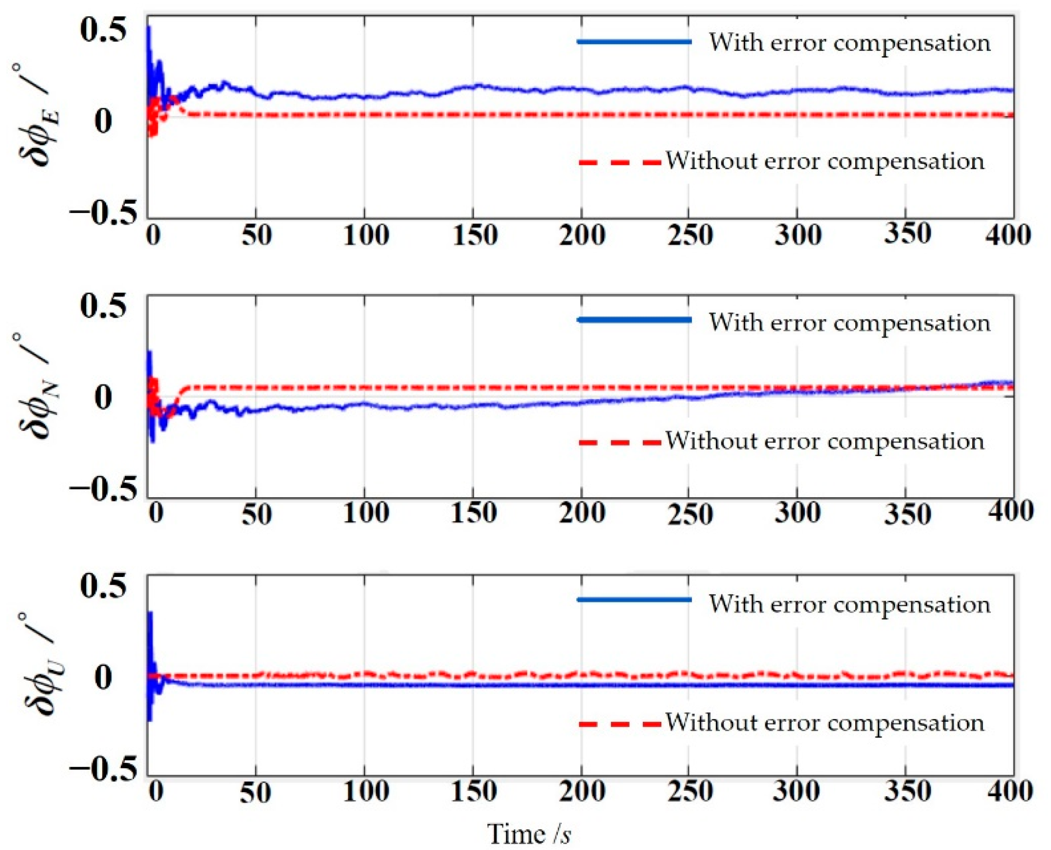
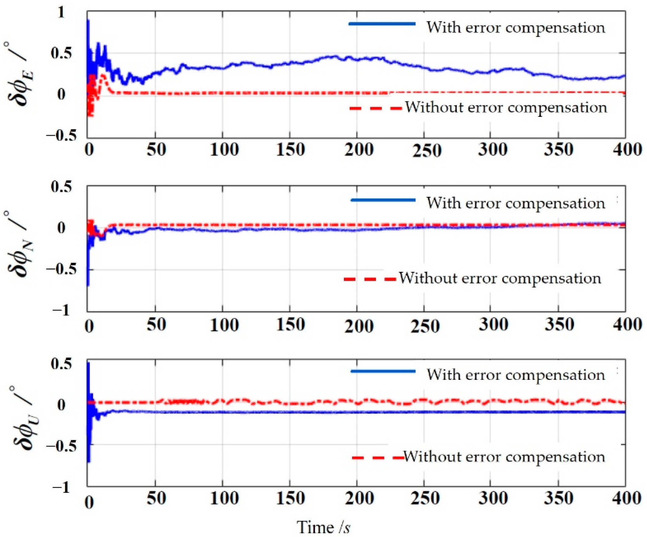
5.3. Simulation Comparison of Filtering Effects for Optimized UKF

Simulation analysis is conducted below for different initial alignment error compensation algorithms to compare the filtering effects among extended Kalman filter (EKF), UKF, and optimized UKF algorithms. It is known that the experimental site has an altitude of 36 m, and latitude and longitude of 34.27° and 117.18°, respectively. The gravitational acceleration, the average earth radius, and the average earth rotation rate are taken as 9.821 m/s2, 6371.393 km, and 15.041°/h, respectively. Both initial pitch angle and roll angle are 0°, and the heading angle is 270°. We assume that three axial error angles φE, φN, and φU in initial alignment are 3°, 3°, and 5°, respectively. Fine alignment filtering is performed using three algorithms, i.e., EKF, UKF, and optimized UKF, separately. The sampling frequency is 200 Hz. The results are shown in Figure 4, Figure 5 and Figure 6.
As can be discerned from Figure 4, Figure 5 and Figure 6, the optimized UKF algorithm has higher accuracy than the EKF and UKF algorithms. The filtering errors of these three algorithms are shown in Table 1.
It can be discerned from Table 1 that, although the optimized UKF algorithm has a larger filtering range in the estimation of error angles in the east and north directions, it has higher accuracy than the EKF and UKF algorithms. In the estimation of heading error angles, the optimized UKF algorithm displays evidently better accuracy and filtering effect than the EKF and UKF algorithms. Therefore, the optimized UKF algorithm can be used in initial alignment to improve the initial alignment accuracy.

6. Installation Error Compensation for the Shearer’s SINS

The installation errors described above include the installation deviation angle error and the lever arm effect error. These two errors are analyzed and compensated separately below.

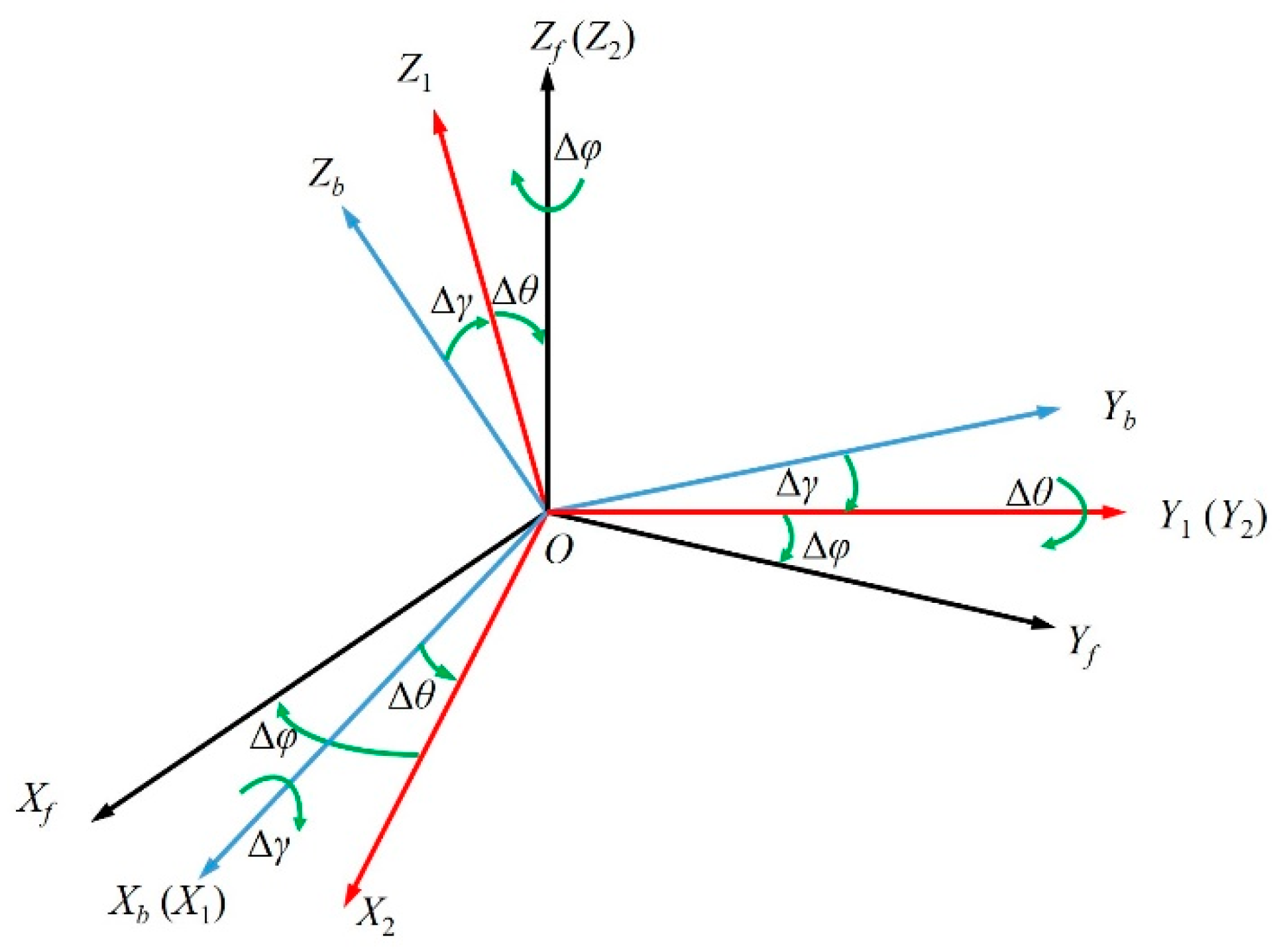
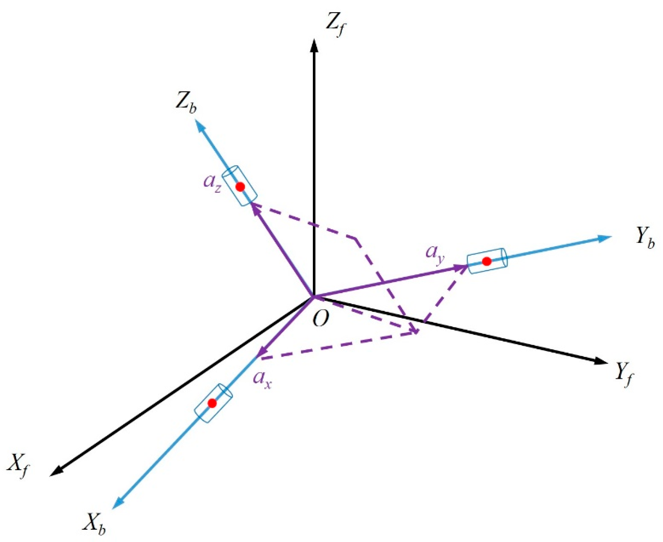
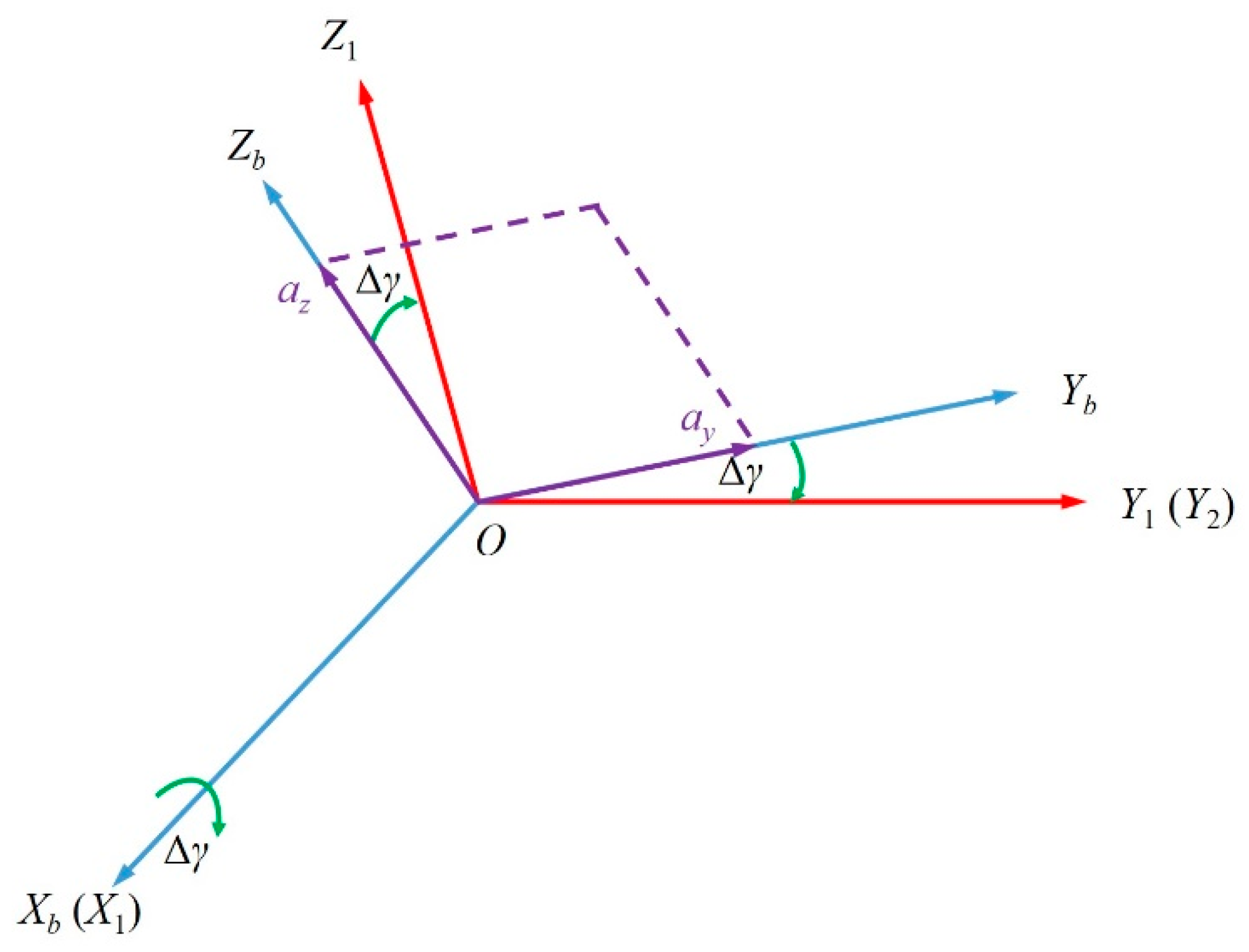
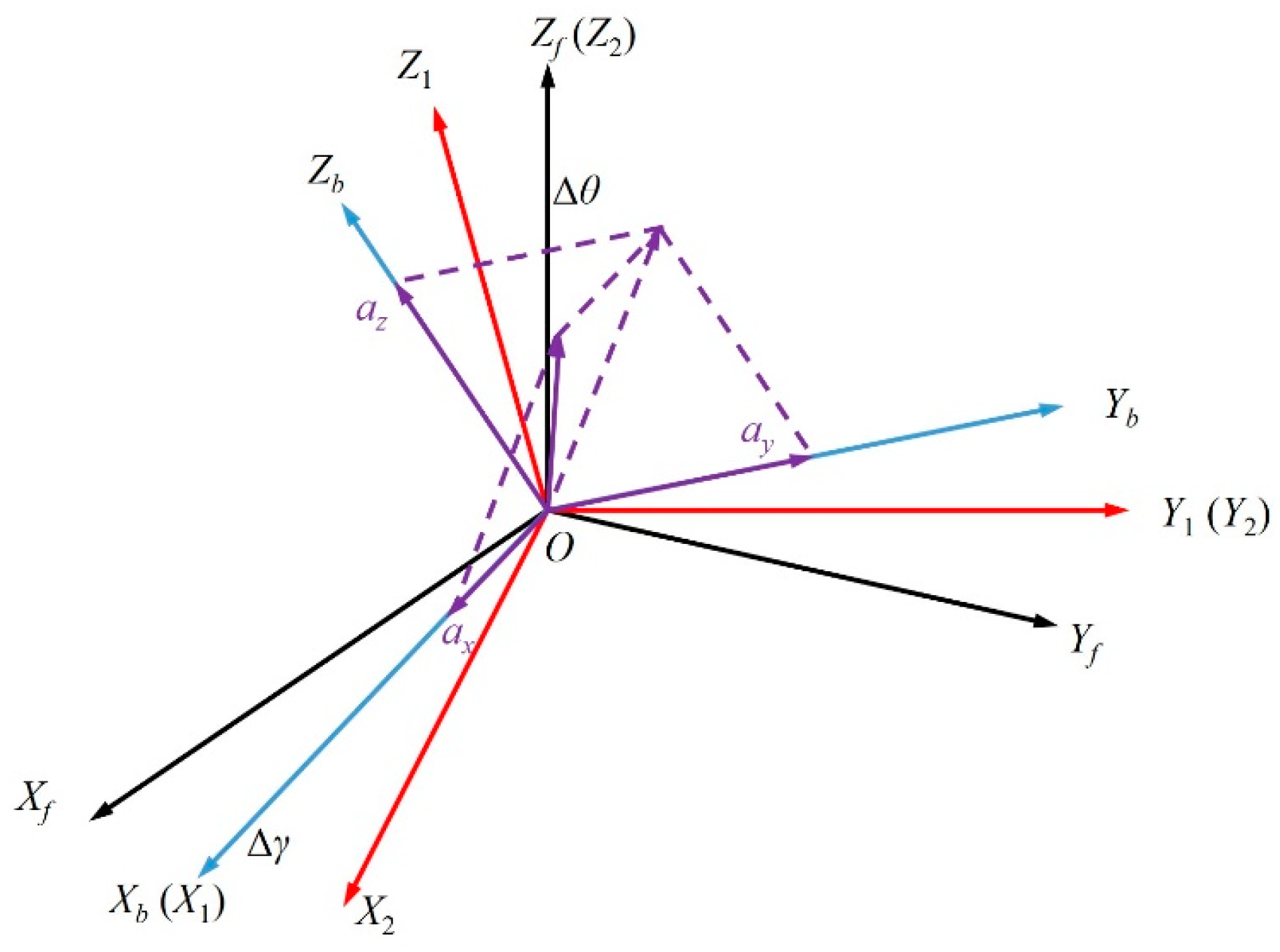
6.1. Static Calibration Model of Installation Deviation Angle

Firstly, the f coordinate system is defined as the right-hand coordinate system of the SINS installation base coordinate system. When the f system and the b system coincide completely, the installation deviation angle error can be guaranteed to be the minimum. However, in the actual installation process, it is extremely difficult to achieve the complete coincidence of the f system and b system. Even if the f system and b system completely coincide, the changes in such external factors as vibration and deformation of the carrier will lead to the non-coincidence of the f system and b system. Let the deviation of heading angle between the f system and b system be ∆φ, the deviation of roll angle be Δγ, and the deviation of pitch angle be Δθ; the orientation relationship is shown in Figure 7. The transformation order from b system to f system is as follows:
O X b Y b Z b Around   X b   axis Rotate   by   Δ γ O X 1 Y 1 Z 1 Around   Y 1   axis Rotate   by   Δ θ O X 2 Y 2 Z 2 Around   Z 2   axis Rotate   by   Δ φ O X f Y f Z f .
As shown in Figure 8, the accelerometers are three cylinders in the three coordinate systems in the figure. The black dot in the middle of each cylinder indicates a measuring point. The three sensing axes are Xb, Yb, and Zb, respectively. If the measured accelerations on the three axes are a x , a y , and a z , respectively, then the acceleration of gravity g = a x 2 + a y 2 + a z 2 .
As shown in Figure 9 and Figure 10, tan Δ γ = a y / a z , tan Δ θ = a x / a y + a z can be obtained from the geometric relationship, but ∆φ cannot be obtained. Therefore, the orientation relationship of the SINS installation deviation angle of the shearer can only solve the static pitch deviation angle and roll deviation angle, but the system accuracy can still be improved to some extent.

6.2. Influence of Installation Deviation Angle Error

(1)
Accelerometer error caused by the installation deviation angle
If the output value of the accelerometer in the b system is f i b b , the output value of the accelerometer in the f system is
f f = C b f f i b b
where C b f is the attitude matrix from the b system to the f system; then, the acceleration error in the f system is
δ f f = f i b b f f = ( I C b f ) f i b b
Then, the acceleration error in the navigation coordinate system (n system) is
δ f n = C f n δ f f = C f n ( I C b f ) f i b b
where C f n is the attitude matrix from the f system to the n system, and I is a unit matrix.
(2)
Angular velocity error caused by the installation deviation angle
The derivation process is the same as above; then,
δ ω i b n = C f n ( I C b f ) ω i b n ,
where δ ω i b n is the measurement error of the gyroscope caused by installation deviation angle, and ω i b b is the ideal output value of the gyroscope.

6.3. Lever Arm Effect Error and Compensation Algorithm

In actual engineering application, the installation position of the inertial measurement unit will not coincide completely with the centroid of the moving target, which will not affect the output of the gyroscope, but the tangential and centripetal accelerations caused by the noncoincidence of the centroids will cause the measurement error of accelerometer which is called “lever arm effect” [30]. The tangential acceleration is proportional to the product of the lever arm length and the carrier swing angular acceleration, and the centripetal acceleration is proportional to the product of the lever arm length and the squared carrier swing angular velocity. They are equivalent to the accelerometer error [31]. The presence of the lever arm effect will also lead to a reduction in the positioning accuracy of the shearer’s SINS, so it needs to be compensated. We establish an inertial coordinate system (i system), and the orientation relationship between i system and b system is shown in Figure 11. Then, the accelerometer error caused by the lever arm effect can be expressed by the following equation:
δ a = d ω i b d t | i × r p + ω i b × ( ω i b × r p ) ,
where δ a is the acceleration output error, ω i b is the angular velocity of the b system relative to the i system, and r p is the lever arm length.
The lever arm effect affects the shearer positioning accuracy, so it is necessary to eliminate or reduce the lever arm effect with error compensation. Let the SINS installation point be P, the position vector of point P relative to Oi be Rip, the position vector of point P relative to Ob be r p , and the position vector from Oi to Ob be R i o b . Then,
R i p = R i o b + r p
then
d R i p d t | i = d R i o b d t | i + d r p d t | i = d R i o b d t | i + d r p d t | b + ω i b × r p
d 2 R i p d t 2 | i = d 2 R i o b d t 2 | i + d d t ( d r p d t | b ) | i + d d t ( ω i b × r p ) | i .
The installation point P of SINS is a fixed point in the carrier coordinate system, so
d r p d t | b = d 2 r p d t 2 | b = 0 ,
then
d 2 R i p d t 2 | i = d 2 R i o b d t 2 | i + d ω i b d t | × r p + ω i b × ( ω i b × r p ) .
Ideally, rp = 0, and there is no error at this moment. However, the installation point P of SINS is not the centroid of the shearer in practice, i.e., rp ≠ 0; therefore, the lever arm effect error introduced by rp is
δ a = a p a b = d 2 R i p d t 2 | i d 2 R i o b d t 2 | i = d ω i b d t | i × r p + ω i b × ( ω i b × r p )
where a p is the specific force at the installation point of the SINS, and a b is the specific force at the centroid of the shearer. The difference between them is the lever arm error δ a , and δ a is positively proportional to rp.
To improve the attitude accuracy of the shearer, error compensation for the lever arm effect is required. Generally, the mechanical theory is used to compensate the lever arm error. When the length rp, angular velocity ω i b , and angular acceleration ( d ω i b / d t ) | i of the lever arm are obtained through calculation, the acceleration affected by the lever arm effect can be obtained, and the outputted acceleration is finally compensated. However, SINS does not output the angular acceleration information, so the angular acceleration ( d ω i b / d t ) | i can only be solved for by differentiating the angular velocity ω i b . Therefore, measurement errors will be introduced when using this method to compensate the lever arm effect error. To avoid this defect, the lever arm effect error is solved for using the Taylor series expansion method in this paper, and a two-sample iteration algorithm is used to make compensation.
When the shearer is stationary and the SINS is in normal operation, the acceleration measured by the accelerometer is the vector sum of the acceleration of gravity at the shearer’s position and the disturbed acceleration caused by the lever arm effect, namely
a b = C n b g n + δ a b ,
where δ a b is the projection of the disturbed acceleration caused by the lever arm effect in the b system.
δ a b = d ω i b b d t | i × r p + ω i b b × ( ω i b b × r p ) = { [ d ω i b b d t | i ] T + ( [ ω i b b ] T ) ( [ ω i b b ] T ) } r p
let { [ d ω i b b d t | i ] T + ( [ ω i b b ] T ) ( [ ω i b b ] T ) } = Q , then
δ a b = Q r p .
Ignoring the influence of the earth’s rotation, if t1 and t2 with a short time interval are selected, the acceleration of gravity can be considered to remain unchanged, i.e., g 1 n = g 2 n . The attitude matrices at t1 and t2 are C b 1 n and C b 2 n , respectively, and the acceleration after attitude transformation is
r p = ( C b 1 n Q 1 C b 2 n Q 2 ) 1 ( C b 1 n a 1 b C b 2 n a 2 b ) .
rp can be solved for with the above equation, and then the lever arm effect error can be solved for according to the Taylor series expansion method, and compensated using the two-sample iteration algorithm.
Let Δ a ( t k + T ) be the lever arm effect error in the time range [ t k , t k + 1 ] , T = t k + 1 t k , and the following equation can be obtained from Equation (41):
Δ a ˙ ( t k + T ) = 1 δ ( d ω i b d t | i × r p + ω i b × ( ω i b × r p ) ) .
For Δ a ( t k + T ) at tk, apply the Taylor series expansion method and find
Δ a ( t k + T ) = Δ a ( t k ) + Δ a ˙ ( t k ) T + T 2 2 ! Δ a ¨ ( t k ) + ,
where Δ a ( t k ) = 0 . The angular velocity of the carrier is fitted by the linear polynomial in the time range [ t k , t k + 1 ] , yielding
ω i b ( t + τ ) = a + 2 b τ , 0 τ t .
Let h = T/2 be the sampling period of the instrument. Carry out integration within [ ( i 1 ) h , i h ] (i = 1, 2);
Δ θ i = ( i 1 ) h i h ω i b ( t + τ ) d τ = ( i 1 ) h i h ( a + 2 b τ ) d τ .
In Equation (49), Δ θ i represents the angular increment of the gyroscope in the time range [ ( i 1 ) h , i h ] (i = 1, 2).
Δ θ 1 = a h + b h 2 Δ θ 2 = a h + 3 b h 2
The following can be obtained from Equation (50):
[ a b ] = [ h h 2 h 3 h 2 ] 1 [ Δ θ 1 Δ θ 2 ] = [ 3 2 h Δ θ 1 1 2 h Δ θ 2 1 2 h 2 Δ θ 1 1 2 h 2 Δ θ 2 ] = [ 3 T Δ θ 1 1 T Δ θ 2 1 T Δ θ 1 1 T Δ θ 2 ] ,
that is,
Δ a ( t k + 1 ) = Δ a ( t k + T ) = 1 δ ( 4 ( 1 T Δ θ 1 + 1 T Δ θ 2 ) × r p + ( 3 Δ θ 1 Δ θ 2 ) × ( ( 3 Δ θ 1 Δ θ 2 ) × r p ) ) + 1 δ ( ( 2 Δ θ 1 + 2 Δ θ 2 ) × ( 4 ( Δ θ 1 + Δ θ 2 ) × r p ) )
Equation (52) is the two-sample iteration algorithm for the lever arm effect error.
The compensation method for the lever arm error can be derived from the above equation:
Δ a 0 = Δ a i Δ a ,
where Δ a 0 is the acceleration increment after error compensation, and Δ a i is the acceleration increment outputted by the accelerometer.

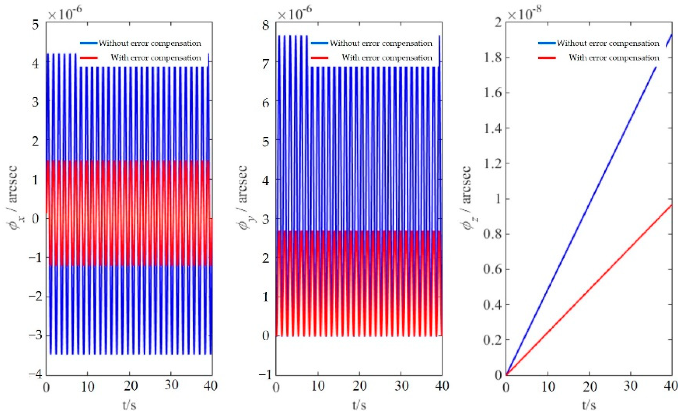
6.4. Simulation Analysis of Lever Arm Effect Error Compensation

The influence of lever arm effect on the attitude angle error in initial alignment is analyzed using the software MATLAB. It is assumed that the error angle of initial attitude angle is φ = [0.1°, 0.1°, 0.5°] (m), the bias drift and random drift of the gyroscope are 0.01°/h and 0.005°/h, respectively, the bias drift and random drift of the accelerometer are 10−4 g and 10−5 g, respectively, and the simulation time is 400 s.
We assume that the shearer motion satisfies sinusoidal motion characteristics as follows:
{ θ = θ m sin 2 π T θ t γ = γ m sin 2 π T γ t φ = φ m sin 2 π T φ t
It is set that θm = 10°, Tθ = 6 s, γm = 10°, Tγ = 8 s, φm = 10°, Tφ = 10 s, and lever arm length rp = [1,1,1] (m). Based on the above parameter values, the accelerations on three axes by level arm effect obtained through simulation are shown in Figure 12.
As can be seen from the figure, the lever arm effect leads to some acceleration errors in all of the east, north and sky directions. To improve the positioning accuracy of shearer SINS, the errors caused by lever arm effect must be compensated. The comparison of attitude angle error between two cases with and without lever arm effect error being compensated is shown in Figure 13 and the maximum attitude angle errors are shown in Table 2.
With other simulation conditions remaining unchanged, the lever arm length is set to rp = [1.5,1.5,1] (m). The attitude angle errors with and without lever arm effect error being compensated are shown in Figure 14, and the maximum attitude angle errors are shown in Table 3.
As can be discerned from Figure 13 and Figure 14 and Table 2 and Table 3, (1) when the initial velocity error is constant, the attitude angle errors tend to be stable after some time; in other words, the attitude angle errors are steady-state errors; (2) in the case of identical lever arm length, the attitude angle errors without lever arm effect error being compensated are evidently greater than those with lever arm effect error being compensated; (3) the attitude angle errors decrease by 73.3%, 60.0% and 85.7%, respectively, after lever arm effect compensation at lever arm length rp = [1,1,1] (m) and by 77.8%, 78.6%, and 88.6%, respectively, after lever arm effect compensation at lever arm length rp = [1.5,1.5,1] (m). The longer the lever arm, the more significant the effect of the lever arm effect error compensation and the shorter the convergence time of attitude angle error. Therefore, lever arm effect error compensation can effectively improve the accuracy of initial alignment; in other words, lever arm effect error compensation has an important role in improving shearer attitude monitoring accuracy.

7. Shearer Vibration Error and Compensation Algorithm

The SINS uses a mathematical platform to substitute for a physical platform, showing great advantages but also losing the isolation effect of the physical platform on vibration. The vibration of the shearer when working underground will also significantly affect the SINS monitoring accuracy, and it is necessary to compensate the vibration error. The errors caused by shearer vibration mainly include coning error and sculling error. The following section mainly focuses on the compensation methods for the above two errors.

7.1. Coning Error and Compensation Algorithm

Affected by the vibration of the working environment and the angular motion of the carrier itself, when the SINS of the shearer produces sinusoidal angular vibrations with the same frequency but different phases on two mutually perpendicular input axes, there will be coning motion forming on the third axis perpendicular to the above two ones, with a constant angular velocity generated [32].
The components of the angular velocity vector in the b system are
{ ω x b = 2 ψ sin 2 ( α / 2 ) ω y b = ψ sin α sin ( ψ t ) ω z b = ψ sin α cos ( ψ t ) .
In Equation (55), ψ is the angular frequency of coning motion, and α is the half-cone angle of coning motion.
Coning motion is the most severe working environment condition, which causes an additional angular velocity—constant angular velocity—with the same property as gyroscope constant drift on the xb axis of the carrier coordinate system. Because the gyroscope on the xb axis of the carrier coordinate system cannot automatically separate other angular velocities with the same property as the gyroscope constant drift, the system will inevitably detect the constant angular velocity to generate a coning error which seriously affects the accuracy of the position and attitude monitoring of SINS. Therefore, the coning error must be compensated.
In this paper, the equivalent rotation vector method is chosen for compensation study for the coning error. The essence of this method is the use of multiple pieces of gyroscope sampled information to fit the angular motion of the carrier in one attitude update period, so that the finite rotation of the carrier is closer to an infinite small rotation to reduce the coning error.
The rotation vector is defined as
Φ = ϕ · n = [ Φ x Φ y Φ z ] T = [ α sin ( ψ t ) α cos ( ψ t ) 0 ] ,
where ϕ = Φ T Φ is the magnitude of the rotation vector, and n is the unit vector on the Euler axis.
The rotation vector differential equation is an important condition for coning error compensation, and the rotation vector differential equation is
Φ ˙ = ω + 1 2 Φ × ω + 1 ϕ 2 [ 1 - ϕ sin ϕ 2 ( 1 cos ϕ ) ] Φ × ( Φ × ω ) ,
where ω = [ ω x ω y ω z ] T is the angular velocity vector, and the sum of the second and third terms on the right is the generated coning error.
From the above equation, it can be obtained that (i) when the motion carrier rotates on a fixed axis, the direction of the rotation vector Φ and that of the angular velocity ω are consistent; (ii) when the last two terms on the right side of the equal sign are zero—in other words, only the angular velocity ω is used for the calculation—there will be no coning error effect, but the direction of the angular velocity is not fixed, so the rotation vector and the angular velocity cannot be guaranteed to have the same direction; (iii) if the last two terms on the right side of the equal sign are not zero, when the direction of the angular velocity and that of the rotation vector are perpendicular to each other—in other words, the motion carrier is in a coning motion—there is a serious coning error effect.
The coefficient of the third term on the right side of Equation (57) is calculated using the Taylor series expansion method, and it is then simplified to yield the following:
Φ ˙ = ω + 1 2 Φ × ω + 1 12 Φ × ( Φ × ω ) .
For the simplicity and real-time performance of calculation, the first two terms of the above equation are taken and reorganized as
Φ ˙ = ω + 1 2 Φ × ω .
Let Φ(h) be the equivalent rotation vector in the time range [ t k 1 , t k ] , where h = t k t k 1 , Φ(0) = 0. Assuming that the helix angle increment θ i in time [ t k 1 , t k ] is sampled at equal intervals for N times, and ω can be fitted with an N−1-degree polynomial about t, then with the transformation equation for rotation vector and quaternion the equivalent rotation vector in the time range [ t k 1 , t k ] is obtained as follows:
Φ = [ - 2 sin α · sin ( ω h / 2 ) · sin [ ω ( t k 1 + h / 2 ) ] 2 sin α · sin ( ω h / 2 ) · cos [ ω ( t k 1 + h / 2 ) ] - 2 sin 2 ( α / 2 ) · sin ω h ] .
The above equation is integrated based on the angular velocity ω, and then reorganized to yield
Δ θ k = [ 2 sin α · sin ( ω h / 2 ) · sin [ ω ( t k 1 + h / 2 ) ] 2 sin α · sin ( ω h / 2 ) · cos [ ω ( t k 1 + h / 2 ) ] 2 ( ω h ) · sin 2 ( α / 2 ) ] ,
where Δ θ k is the angular increment between two adjacent sampling time points, i.e., t k 1 and t k . The coning error is expressed as Δ Φ = Φ - Δ θ k . With the expressions of angular increment and rotation vector, it is obtained through analysis that the first two terms of coning error ΔΦ are periodic functions, and the third item is an aperiodic function. Therefore, the best result of coning error compensation can be achieved when the aperiodic term is minimum.

7.2. Simulation Analysis of Coning Error Compensation

The error results before and after coning error compensation are compared through simulation. The simulation parameters are as follows: the shearer body mass 36.5 t, the rotational angular velocity of the earth ωie = 7.29 × 10⁻⁵ rad/s, the earth radius RM = 6.36 × 10⁶ km, RN = 6.39 × 10⁶ km, the simulation time 40 s, α = 1°, ω = 2π rad/s, h = 10 ms, and n = 3. The coning error curve of the shearer SINS is shown in Figure 15. The coning error exhibits evident periodic fluctuation in the X- and Y-axis directions, with a small wave with a different period superposed on the periodic wave of the curve. The coning error exhibits a linear relationship in the Z-axis direction. On the whole, the SINS exhibits coning drift error on the Z axis and tiny oscillating errors on the X and Y axes. The comparison of results before and after coning error compensation is shown in Figure 16. The coning error has similar change trends before and after compensation, but the values are different. The maximum errors in the three axis directions are 4.2 × 10⁻⁶, 7.7 × 10⁻⁶, and 1.95 × 10⁻⁸, respectively, without coning error being compensated, and they are 1.5 × 10⁻⁶, 2.8 × 10⁻⁶, and 0.98 × 10⁻⁸, respectively, with coning error being compensated, decreasing by 64.3%, 63.6%, and 49.7%, respectively. The coning error effect is reduced significantly and the monitoring accuracy is improved effectively.

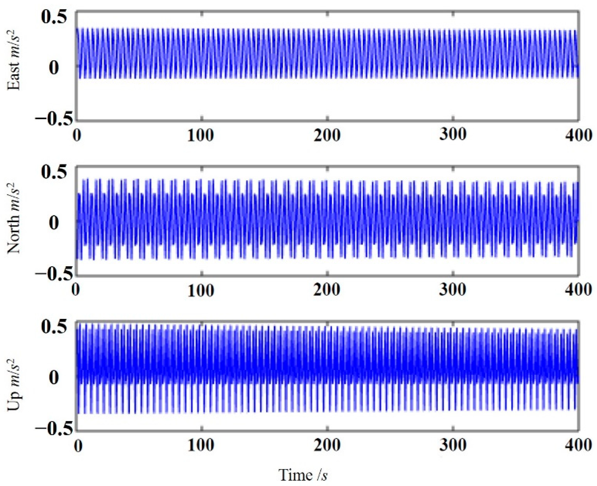
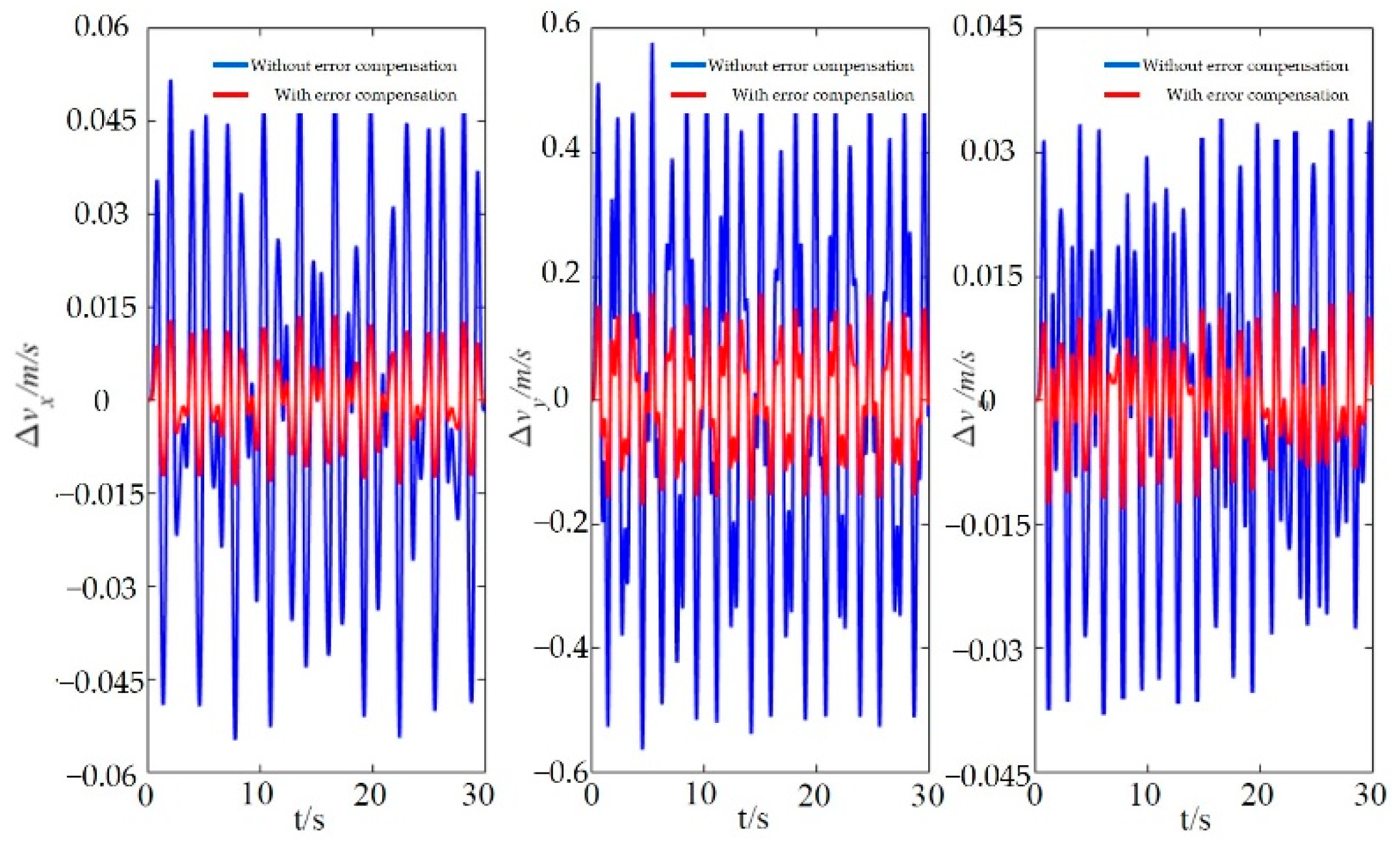
7.3. Sculling Error and Compensation Algorithm

When the shearer is working underground in a coal mine, the angular vibration and linear vibration of SINS will be probably caused by such factors as eccentricity of the traveling wheel, gear meshing clearance, and the undulation of the coal seam floor. When the in-phase angular and linear vibrations occur simultaneously on the two orthogonal axes of the shearer, a sculling motion will be formed on the third axis perpendicular to the above two axes, with a constant velocity generated.
Assuming that there are angular vibration and linear vibration with the same frequency along the X axis and Y axis of the carrier, respectively, the angular vibration
α ( t ) = [ A α cos Ω t 0 0 ] ,
the linear vibration (displacement)
P ( t ) = [ 0 A p cos ( Ω t + φ ) 0 ] ,
and the angular velocity
ω ( t ) = α ˙ ( t ) = [ A α sin Ω t 0 0 ] ,
the velocity
v ( t ) = P ˙ ( t ) = [ 0 A p Ω sin ( Ω t + φ ) 0 ] ,
and the acceleration
f ( t ) = v ˙ ( t ) = [ 0 A p Ω 2 cos ( Ω t + φ ) 0 ] ,
then there will be a velocity full flow along the third axis
Δ v s c u l m = 1 2 t m 1 t m [ α ( t ) × f ( t ) + v ( t ) × ω ( t ) ] d t = [ 0 0 ( 1 / 2 ) A α A p Ω 2 T cos φ ] .
When the carrier makes a sculling motion, a direct component of the velocity - ( 1 / 2 ) A α A p Ω 2 T cos φ , that is, a sculling error, is generated on the third orthogonal axis. Under the condition of high-frequency motion, the SINS will produce sculling error in the velocity calculation. To improve the position and attitude monitoring accuracy of the SINS, the sculling error must be compensated in the velocity calculation.
Assuming that the information on Δ θ i and Δ v i can be obtained by sampling ω b and f b for N times at equal intervals in the time range of [ t m 1 ,   t m ] , and that ω and f can be fitted with an N−1-degree polynomial about t, then the expression of sculling error compensation algorithm is obtained as follows:
Δ v s c u l m = i = 1 N 1 j = i + 1 N K i j [ Δ θ i × Δ v j + Δ v i × Δ θ j ] .
Similar to the rotation vector algorithm, the above equation is simplified as follows:
Δ v s c u l m = i = 1 N - 1 K i [ Δ θ i × Δ v N + Δ v i × Δ θ N ] .
With the minimum drift error of the algorithm under the sculling motion condition as the accuracy criterion, the four-sample optimal compensation algorithm is obtained as follows:
Δ v s c u l m = [ 54 105 θ 1 + 92 105 θ 2 + 214 105 θ 3 ] × Δ v 4 + [ 54 105 Δ v 1 + 29 105 Δ v 2 + 214 105 Δ v 3 ] × θ 4 .

7.4. Simulation Analysis of Sculling Error Compensation

Assuming the carrier is in angular vibration around the X axis and in linear vibration at the same frequency around the Y axis, and the vibration angular frequency is Ω = 2 pf, the sculling vibration model is
ω b ( t ) = [ B Ω cos ( Ω t ) 0 0 ] , f b ( t ) = [ 0 C sin ( Ω t ) 0 ] .
Simulation is carried out for the above equation. The specific parameters are as follows: simulation time 30 s, vibration frequency f = 1 Hz, B = 0.1°, C = 0.01 g, T = 0.024 s. The velocity calculation period T = N × ΔT (where N is the number of sampling times, i.e., the number of sub-samples in the compensation algorithm). The sculling error curve of the shearer SINS is shown in Figure 17. The curve is formed by mutually superposed sine functions with different periods in the X-, Y-, and Z-axis directions. There is linear vibration in the Y-axis direction, so the sculling error is the largest in the Y-axis direction, with a maximum value of 0.145 m/s.
The comparison of results before and after sculling error compensation is shown in Figure 18. The maximum sculling errors in the X-, Y-, and Z-axis directions are 0.055 m/s, 0.58 m/s, and 0.038 m/s, respectively, without sculling error being compensated, and they are 0.013 m/s, 0.18 m/s, and 0.014 m/s, respectively, with sculling error being compensated, decreasing by 76.4%, 70.0%, and 63.2%, respectively. The sculling error effect is reduced significantly and the monitoring accuracy is improved effectively.

8. Conclusions

  • Based on the basic principle of the SINS, a real-time algorithm for solving the attitude, velocity, and position of the shearer is constructed, and the specific process of the coarse alignment and fine alignment of the SINS is studied. The main error terms affecting the accuracy of SINS are analyzed for the shortcoming that the accumulated errors of SINS at long endurance are difficult to be effectively corrected.
  • The initial alignment of SINS is carried out based on the optimized unscented Kalman filter algorithm. The influence of installation deviation angle on SINS error is clarified, an effective installation error compensation algorithm is proposed, and the lever arm effect error compensation method is optimized, the influence of lever arm effect on the system accuracy is analyzed through simulation. Given the influence of the strong vibration environment of the shearer on the accuracy of SINS, the coning error and sculling error caused by the shearer vibration are compensated based on the rotation vector method.
  • This paper conducts an in-depth study on the real-time and accurate shearer attitude sensing and provides a complete set of theories and methods to improve the attitude sensing accuracy of the underground shearer, simulation results also verify that the theories and methods can significantly improve the perception accuracy, which not only helps enrich the research results of intelligent sensing at fully mechanized mining face, but also can provide theoretical and technical reference for production state prediction at fully mechanized mining face and intelligent control of underground mining equipment.

9. Future Developments

The authors believe that in-depth research efforts can be made from the following aspects. At present, for many shearers in mines, the attitude sensing not only depends on the SINS technique but also employs other shearer positioning methods for redundancy constraint. Therefore, in the measurement of shearer attitude, there is not only information outputted from SINS but also from other positioning methods, forming a complex multi-sensor redundancy system. It is needed to develop an optimal shearer attitude estimation and fusion algorithm to study the error characteristics of fused and estimated data of shearer attitude information from multiple sensors so as to further improve shearer attitude sensing accuracy.

Author Contributions

Conceptualization, G.W. and X.F.; validation, G.W., X.F. and Y.S.; formal analysis, M.L. and N.C.; investigation, G.W., X.F. and Y.S.; data curation, M.L. and N.C.; writing—original draft preparation, G.W. and X.F.; writing—review and editing, G.W. and Y.S.; supervision, X.F.; funding acquisition, G.W., X.F. and M.L. All authors have read and agreed to the published version of the manuscript.

Funding

This research was funded by the National Natural Science Foundation of China, grant number 52104167, 51874276 and 52004273, and the Fundamental Research Funds for the Central Universities, grant number 2020ZDPY0209.

Institutional Review Board Statement

Not applicable.

Informed Consent Statement

This study did not involve humans.

Acknowledgments

The authors gratefully acknowledge the financial support of the above organization.

Conflicts of Interest

The authors declare no conflict of interest.

References

  1. Wang, G.; Xu, Y.; Ren, H. Intelligent and ecological coal mining as well as clean utilization technology in China: Review and prospects. Int. J. Min. Sci. Technol. 2019, 29, 161–169. [Google Scholar] [CrossRef]
  2. Xie, H.; Ju, Y.; Gao, F.; Gao, M.; Zhang, R. Groundbreaking theoretical and technical conceptualization of fluidized mining of deep underground solid mineral resources. Tunn. Undergr. Space Technol. 2017, 67, 68–70. [Google Scholar] [CrossRef]
  3. Ge, S.; Hao, S.; Zhang, S.; Zhang, X.F.; Zhang, L.; Wang, S.B. Status of intelligent coal mining technology and potential key technologies in China. Coal Sci. Technol. 2020, 48, 28–46. [Google Scholar]
  4. Xie, H.; Wang, J.; Wang, G. New ideas of coal revolution and layout of coal science and technology development. J. China Coal Soc. 2018, 43, 1187–1197. [Google Scholar]
  5. Xinqiu, F.; Minfu, L.; Shuang, L. Research on the key technologies of multi-parameter accurate perception and security decision in intelligent working face. J. China Coal Soc. 2020, 45, 493–507. [Google Scholar]
  6. Thrybom, L.; Neander, J.; Hansen, E.; Landernas, K. Future Challenges of Positioning in Underground Mines. IFAC-Pap. Line 2015, 48, 222–226. [Google Scholar] [CrossRef]
  7. Wang, G.; Fan, J.; Xu, Y. Innovation progress and prospect on key technologies of intelligent coal mining. Ind. Mine Autom. 2018, 44, 5–12. [Google Scholar]
  8. Ren, H.; Wang, G.; LI, S.; Niu, J. Development of intelligent sets equipment for fully-mechanized 7 m height mining face. Coal Sci. Technol. 2015, 43, 116–121. [Google Scholar]
  9. Ge, S.; Wang, Z.; Wang, S. Study on key technology of internet plus intelligent coal shearer. Coal Sci. Technol. 2016, 44, 1–9. [Google Scholar]
  10. Wang, S.; Zhang, B.; Wang, S.; Ge, S. Dynamic Precise Positioning Method of Shearer Based on Closing Path Optimal Estimation Model. IEEE Trans. Autom. Sci. Eng. 2019, 16, 1468–1475. [Google Scholar]
  11. Zhang, B.; Wang, S.; Ge, S. Effects of initial alignment error and installation noncoincidence on the shearer positioning accuracy and calibration method. J. China Coal Soc. 2017, 42, 789–795. [Google Scholar]
  12. Yang, H.; Li, W.; Zhang, H. Fault tolerant integrated positioning system based on SINS/UWB in complex environment. Chin. J. Sci. Instrum. 2017, 38, 2177–2185. [Google Scholar]
  13. Wu, G.; Fang, X.; Zhang, L.; Liang, M.; Lv, J.; Quan, Z. Positioning accuracy of the shearer based on a strapdown inertial navigation system in underground coal mining. Appl. Sci. 2020, 10, 2176. [Google Scholar] [CrossRef] [Green Version]
  14. Wang, S.; Wang, S. Improving the Shearer Positioning Accuracy Using the Shearer Motion Constraints in Longwall Panels. IEEE Access 2020, 8, 52466–52474. [Google Scholar] [CrossRef]
  15. Cao, B.; Wang, S.; Ge, S.; Liu, W. Improving the Positioning Accuracy of UWB System for Complicated Underground NLOS Environments. IEEE Syst. J. 2022, 16, 1808–1819. [Google Scholar] [CrossRef]
  16. Zhang, Z.B.; Xu, X.L.; Yan, L.L. Underground localization algorithm of wireless sensor network based on Zigbee. J. China Coal Soc. 2009, 34, 125–128. [Google Scholar]
  17. Xu, C.Y.; Song, Y.; Song, J.C. Development of the device to detect the position of coal mining machine by infrared ray based on MCU. J. China Coal Soc. 2011, 36, 167–171. [Google Scholar]
  18. Jonathon, C.R.; Chad, O.H.; Mark, T.D. Longwall automation: Trends, challenges and opportunities. Int. J. Min. Sci. Technol. 2017, 27, 733–739. [Google Scholar]
  19. Ge, S. The development of coal shearer technology (part nine)- environment sensing technology. China Coal 2021, 47, 1–17. [Google Scholar]
  20. Dziurzyński, W.; Krach, A.; Krawczyk, J.; Pałka, T. Numerical Simulation of Shearer Operation in a Longwall District. Energies 2020, 13, 5559. [Google Scholar] [CrossRef]
  21. Shen, Y.; Wang, P.; Zheng, W.; Ji, X.; Jiang, H.; Wu, M. Error Compensation of Strapdown Inertial Navigation System for the Boom-Type Roadheader under Complex Vibration. Axioms 2021, 10, 224. [Google Scholar] [CrossRef]
  22. Fang, X.; Wu, G. Researches on simultaneous extraction of coal and gas in protective layer with a manless working face. Disaster Adv. 2013, 6, 200–207. [Google Scholar]
  23. Fang, X.; Zhao, J.; Hu, Y. Tests and error analysis of a self-positioning shearer operating at a manless working face. Min. Sci. Technol. 2010, 20, 53–58. [Google Scholar] [CrossRef]
  24. Fang, X.Q.; He, J.; Guo, M.J.; Zhang, B. Study on Unmaned Workface Mining Technology. Sci. Technol. Rev. 2008, 9, 56–61. [Google Scholar]
  25. Fang, X.Q.; He, J.; Zhang, B. Autonomous positioning system of Shearer in unmanned working face. J. Xian Univ. Sci. Technol. 2008, 28, 349–353. [Google Scholar]
  26. Hai, Y.; Wei, L.I.; Luo, C.M.; Fan, M.; Yng, B.H. Experimental study on position and attitude technique for shearer using SINS measurement. J. China Coal Soc. 2014, 39, 2550–2556. [Google Scholar]
  27. Zhang, B.; Fang, X.; Zou, Y.; Yu, R.; Cheng, Y. Auto-positioning system of shearer operating on manless working face based on gyroscope and odometer. Min. Process. Equip. 2010, 9, 10–13. [Google Scholar] [CrossRef]
  28. Si, Z.; Li, W.; Tong, J. Research on lever arm effect error compensation method for strap-down inertial navigation system of shearer. Ind. Mine Autom. 2019, 45, 56–61. [Google Scholar]
  29. Kushner, H.J. Dynamical Equations for Optimal Nonlinear Filtering. J. Differ. Equ. 1967, 3, 179–190. [Google Scholar] [CrossRef] [Green Version]
  30. Song, W.; Jianye, L.; Jizou, L. Research on influence induced by installation error in SINS. Transducer Microsyst. Technol. 2007, 26, 29–31. [Google Scholar]
  31. Ben, Y.; Zhang, Q.; Zang, X.; Huang, L.; Li, Q.; Wang, G. Effect of the outer lever arm on in-motion gyrocompass alignment for fiber-optic gyro strapdown inertial navigation system. Opt. Eng. 2017, 56, 044106. [Google Scholar] [CrossRef]
  32. Wang, L.; Wu, W.; Pan, X.; Li, G. Estimation and compensation for dynamic bending error parameters of mechanical dithered RLG sensitive axis. J. Chin. Inert. Technol. 2016, 24, 828–831. [Google Scholar]
Figure 1. Layout of three machines at a typical fully mechanized mining face; (a) front view; (b) top view.
Applsci 12 10848 g001
Figure 2. Orientation relationship between b system and n system.
Applsci 12 10848 g002
Figure 3. Principle of the shearer positioning system based on SINS.
Applsci 12 10848 g003
Figure 4. Filtering results of east error angle.
Applsci 12 10848 g004
Figure 5. Filtering results of north error angle.
Applsci 12 10848 g005
Figure 6. Filtering results of heading error angle.
Applsci 12 10848 g006
Figure 7. Installation deviation angle of SINS.
Applsci 12 10848 g007
Figure 8. Installation deviation of SINS.
Applsci 12 10848 g008
Figure 9. Roll deviation angle of SINS.
Applsci 12 10848 g009
Figure 10. Pitch deviation angle of SINS.
Applsci 12 10848 g010
Figure 11. Schematic diagram of the lever arm effect.
Applsci 12 10848 g011
Figure 12. Acceleration of rod arm effect.
Applsci 12 10848 g012
Figure 13. The comparison of attitude angle error.
Applsci 12 10848 g013
Figure 14. The comparison of attitude angle error after changing the length of the arm.
Applsci 12 10848 g014
Figure 15. Shearer SINS coning error.
Applsci 12 10848 g015
Figure 16. Contrast with or without coning error compensation.
Applsci 12 10848 g016
Figure 17. Shearer SINS sculling error.
Applsci 12 10848 g017
Figure 18. Contrast with or without sculling error compensation.
Applsci 12 10848 g018
Table 1. Filtering Results of error angle.
φEφNφU
ErrorVarianceErrorVarianceErrorVariance
EKF−0.5100.01030.3250.0056−18.4789.4679
UKF0.3020.0118−0.2530.00688.9357.6143
Optimized UKF−0.1230.01270.1020.0059−4.2394.8291
Table 2. Maximum attitude angle errors.
δ φ E δ φ N δ φ U
Without error compensation0.45°0.25°0.35°
With error compensation0.12°0.10°0.05°
Table 3. Maximum attitude angle errors (changing the length of the arm).
δ φ E δ φ N δ φ U
Without error compensation0.90°0.70°0.70°
With error compensation0.20°0.15°0.08°
Publisher’s Note: MDPI stays neutral with regard to jurisdictional claims in published maps and institutional affiliations.

