Article

Modeling and Experimental Study of the Dual Cylinder Fluid Inerter

1
School of Mechanical Engineering, Beijing Institute of Technology, Beijing 100081, China
2
Suspension System Technology Department, China North Vehicle Research Institute, Beijing 100072, China
*
Author to whom correspondence should be addressed.
Appl. Sci. 2022, 12(21), 10849; https://doi.org/10.3390/app122110849
Submission received: 12 September 2022 / Revised: 28 September 2022 / Accepted: 29 September 2022 / Published: 26 October 2022
(This article belongs to the Topic Fluid Mechanics)

Abstract

:
The fluid inerter is a new mechanical element which has received great attention in the field of vibration reduction. However, due to the influence of secondary flow in the curved channel, the damping force is too large and the inertia force is relatively small, which limits the engineering applications of the single-cylinder fluid inerter. To eliminate the influence of secondary flow in the single-cylinder fluid inerter, this paper proposes a dual-cylinder fluid inerter that has a straight tube instead of the spiral pipe or spiral groove. We Analyze the working principle, derive conditions of free movement, establish the damping force and inertia force model, and prove the validity of the model through bench testing. Contrastingly, it is found that the maximum parasitic damping force is only 40.32% of the single-cylinder structure, but the inertia force increases to 180.96% of the single-cylinder structure. The proposed inerter greatly increases the proportion of inertia force, and provides a new scheme for engineering applications.

1. Introduction

In 2002, Smith of Cambridge University proposed the concept of an inerter [1] and constructed a new vibration-reduction theoretical system of “inerter–spring–damping”. Inerters can help solve common problems in the field of vibration reduction, improving the performance of vehicle suspensions [2], enhancing the cross-country mobility of multi-axle vehicles [3], improving the safety of high-rise buildings, and greatly attenuating vibrations from earthquakes [4] and typhoons [5]; inerters also extend to other technical fields, such as resonance-suppression of ships [6], long-span cables [7] and bridges [8], high-speed rail suspensions [9], and aerospace [10].
Reference [11] first proposed the concept of a fluid inerter. The main source of inertia force is the fluid in the slender spiral tube or spiral groove, and the generation device of inertia force is a dual-rod single cylinder. It has the advantages of a large transmission ratio, small back gap, long lifespan, simple structure, and so on.
Swift and Smith [12] established the first mechanical model of single-cylinder fluid inerters. Through the quantitative analysis of inertia force and parasitic damping force, it was proven that when fluid reciprocates through a slender spiral tube or spiral slot at high speed, a huge parasitic damping force will be generated, and the proportion of inertia force is relatively small. To control the parasitic damping force, researchers from the University of Sheffield [13,14] and the University of Bristol [15] used magnetorheological fluid as a fluid medium to adjust the size of the parasitic damping force through an external magnetic field. Wang Le and Mao Ming [16] adopted the method of fluid mechanics analysis to build a mechanical model of single-cylinder fluid inerters, proving that the parasitic damping force mainly comes from the secondary turbulence of the helical pipeline section. The magnitude and source of parasitic damping force have been fully studied, and reducing the resistance of fluid media has become a new hotspot in this field, but with little effect.
Because of this situation, this paper draws on the dual-cylinder transmission mechanism of a hydraulic piston mass inerter [17] and proposes a new structural scheme, a dual-cylinder fluid inerter [18]. Where a single-cylinder fluid inerter has a spiral tube or groove, we instead it with a straight tube in order to eliminate the secondary flow of the spiral tube section, and the use of two double-acting single-rod cylinders instead of the original double-rod cylinder greatly reduces the parasitic damping force, while increasing the inertia force.

2. Structure and Principle of the Dual-Cylinder Fluid Inerter

2.1. Structure and Working Principle

The dual-cylinder fluid inerter consists of two cylinders, as shown in Figure 1. The inertia force output cylinder is composed of cylinder 13 and piston 12. The flow-regulating cylinder is composed of cylinder 7 and piston 8. Terminal 1 is on the left side of cylinder 13, and terminal 16 on the right side of piston rod 18. Terminal 1 and terminal 16 are the two inertia force output terminals. Pipeline 4 is used to connect oil port 3 and oil port 5, so that the main chamber 2 and 6 are connected, and pipeline 11 is connected to oil port 14 and oil port 10, so that the annular chamber 9 and 15 are connected.
A closed liquid-flow loop is formed by main chamber 2, oil port 3, pipeline 4, oil port 5 and main chamber 6. Another closed liquid flow loop is constructed by annular chamber 9, oil port 10, pipeline 11, oil port 14 and annular chamber 15. When terminal 1 and 16 move relative to each other, they force the oil to flow back-and-forth in the two loops, creating inertia forces.

2.2. Condition of Free Motion

Suppose that the effective area of main chamber 2 is A2, that of main chamber 6 is A6, that of annular chamber 15 is A15, and that of annular chamber 9 is A9. Suppose that the relative movement velocity between terminal 1 and terminal 16 is x ˙ , and the volume flow discharged from main chamber 2 is A 2 x ˙ . According to the conservation rule of oil volume, the volume flow Q9 out of annular chamber 9 is equal to the flow Q15 into annular chamber 15:
Q 15 = Q 9 = A 2 x ˙ A 6 A 9
To make sure there is no motion interference in the reciprocating process of the piston, the discharge (or inflow) Q2 of main chamber 2 and the inflow (or outflow) Q15 of annular chamber 15 should obey the following relationship:
Q 2 Q 15 = A 2 A 15
Substitute Equation (1) into Equation (2), and obtain:
A 6 A 9 = A 2 A 15
A2/A15 is the ratio of the effective area of the main chamber of the inertia force output cylinder to the annular chamber. A6/A9 is the ratio of the effective area of the main chamber and the annular chamber of the flow-regulating cylinder. As long as they are equal, they can move back-and-forth without motion interference.

3. Modeling of Mechanical Properties of a Dual-Cylinder Fluid Inerter

3.1. Modeling of Inertia Forces

The inertia force at both terminals of the inerter is proportional to its relative acceleration. The ratio is called the inertance, and the unit is kg. Assuming that the inertance of the fluid inerter is B, the stored kinetic energy E is:
E = 1 2 B x ˙ 2
The kinetic energy of the system is provided by the high-speed reciprocating flow of the fluid in two closed loops, so:
E = 1 2 ρ 4 L 4 A 4 v 4 2 + 1 2 ρ 11 L 11 A 11 v 11 2
where ρ4 is the density of the fluid in pipeline 4, L4 is the length of pipeline 4, v4 is the linear velocity of the fluid in pipeline 4, ρ11 is the density of the fluid in pipeline 11, L11 is the length of pipeline 11, and v11 is the linear velocity of the fluid in pipeline 11. Since the volume of oil is conserved, it can be obtained:
v 4 = A 2 A 4 x ˙ v 11 = A 15 A 11 x ˙
In combination with (4)–(6), the inertance B is:
B = ρ 4 L 4 A 4 A 2 A 4 2 + ρ 11 L 11 A 11 A 15 A 11 2
where ρ4L4A4 and ρ11L11A11 are the masses of the fluid in pipelines 4 and 11, respectively. Therefore, the size of B has nothing to do with the structural size of the flow-regulating cylinder, but only with the inertia force output cylinder and the pipeline.

3.2. Damping Force Modeling

Part of the damping force is caused by the friction between cylinder and piston, and the other part is caused by the viscous resistance of oil flowing back-and-forth. When the relative velocities of the two terminals of the dual-cylinder fluid inerter are low, damping and inertia forces are small, and friction dominates. Therefore, in this paper, a 0.01 Hz quasi-static sinusoidal displacement signal is used as the input, and the mean value F ¯ of the absolute values of the output forces at both terminals is used to approximate the friction force Ff; that is to say:
F f = F ¯ sign S ˙
where sign is the sign function, indicating that the direction of friction force Ff is opposite to the relative velocity S. The pressure-loss along the path when the fluid flows through pipelines 4 and 11 is the source of damping force, and the pressure-loss coefficient λ [19] is:
λ = 75 R e , R e 2320 0.0025 R e 1 3 , 2320 < R e 4000 0.3164 R e 0.25 , 4000 < R e 10 5 0.0032 + 0.221 R e 0.237 , 10 5 < R e 10 6
where Re is the Reynolds number; the calculation formula is:
R e = ρ v d μ
where ρ is fluid density, v is fluid velocity, d is flow-channel diameter, and µ is fluid dynamic viscosity. The pressure-drop ∆p [20] generated by liquid flow damping is:
Δ p = 1 2 ρ v 2 λ L d
where L is the length of a straight pipe. The damping-loss ∆p4 along pipeline 4 is:
Δ p 4 = p 2 p 6 = 1 2 ρ 4 v 4 2 λ 4 L 4 d 4
where p2 is the pressure in main chamber 2 and p6 is the pressure in main chamber 6. Similarly, the damping-loss ∆p11 along pipeline 11 is:
Δ p 11 = p 9 p 15 = 1 2 ρ 11 v 11 2 λ 11 L 11 d 11
where p9 is the pressure in annular chamber 9 and p15 is the pressure in annular chamber 15. The damping force Fc is:
F c = A 2 p 2 A 15 p 15 + F f
In combination with Formulas (3), (12)–(14), the following can be obtained:
F c = Δ p 4 A 2 + Δ p 11 A 15 + F f

3.3. Simulation of Mechanical Properties

The force generated by the dual-cylinder fluid inerter is the resultant force of inertia force and damping; i.e., F is:
F = B x ¨ + F c
MATLAB was used to write programs to establish the inertial force Fb, damping force Fc and resultant force F by combining Equations (7), (15), and (16). The structural parameters are shown in Table 1, and the results are shown in Table 2.
The inertial and damping forces are shown in Figure 2.
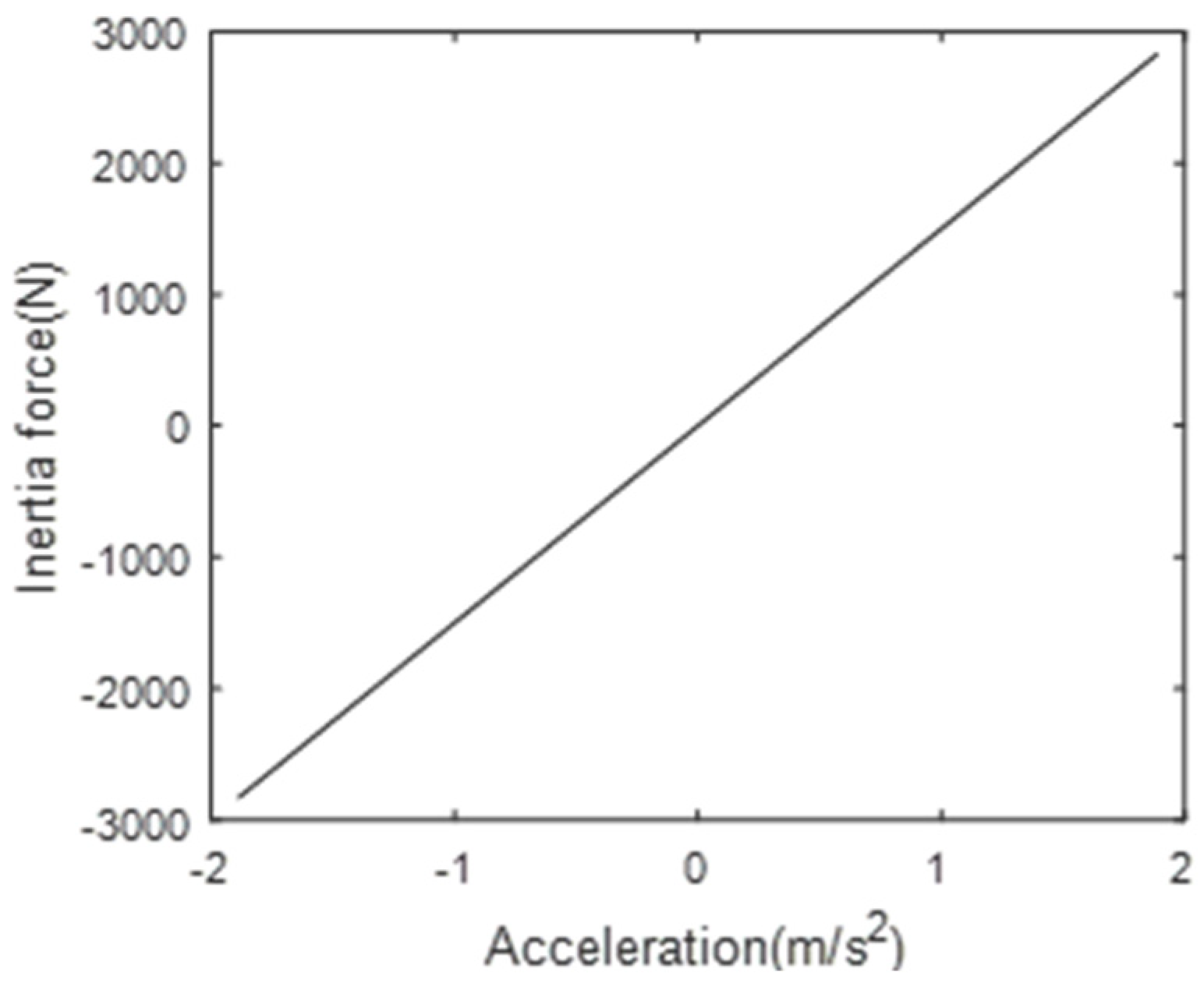
As can be seen from Figure 3 and Figure 4, the mechanical properties of a dual-cylinder fluid inerter are equivalent to nonlinear damping and linear inerter in parallel.
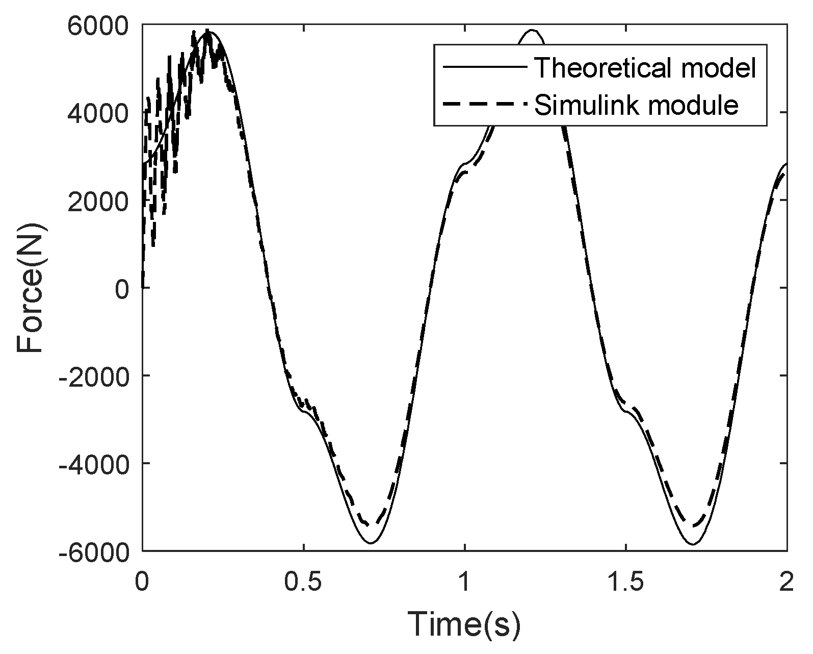
In Figure 5, the solid line is the resultant force calculated by Formula (16), and the dotted line is the result calculated by Simulink/Hydraulic Segmented Pipe LP. The Segmented Pipe LP module could consider the inertia force and damping force of the fluid simultaneously. “The Segmented Pipe LP” module in Simulink was based on the finite-element idea. Except in the initial stage of loading, there was shock in the Segmented Pipe LP module, and after stabilizing, the results of the above two methods were highly consistent, which proved the correctness of the established dual-cylinder fluid inerter mechanical model before the test comparison.
The oscillations in the calculation results of Simulink are a normal physical phenomenon. At the moment of loading, the internal pressure of the fluid inerter transiently fluctuates, and gradually converges to a steady state after a period of oscillation. The mechanical model established by Formula (16) is based on the empirical formula of fluid mechanics and is a description of a steady state, so there is no oscillation in Figure 5.

4. Comparative Study with Single-Cylinder Fluid Inerter

According to the literature [16], the mechanical model of a single-cylinder fluid inerter is constructed. The diameter of the cylinder, the diameter of the piston rod, and the length and diameter of the pipeline are the same as those of the dual-cylinder fluid inerter. The specific parameters are shown in Table 3.
Inertance of the single-cylinder fluid inerter is 828 kg, and inertance of the dual-cylinder fluid inerter is 1529 kg. When L4 + L11 = 10, that is to say, the total length of the pipeline is 10 m, inertance is in a linear relationship with L4, as shown in Figure 6. When L4 = 0, inertance is the same as in a single-cylinder fluid inerter, and inertance increases linearly with an increase in L4. Under the condition that the total pipe length is the same, different inertance values can be obtained by changing the lengths of L4 and L11.
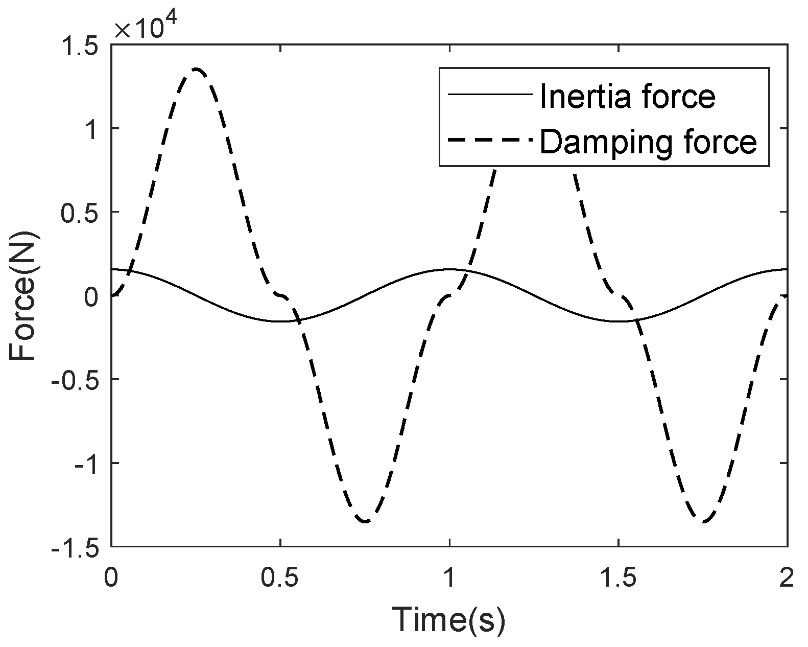
In the single-cylinder fluid inerter, as the secondary flow on the section of the pipe increases the damping force when the fluid flows in the spiral pipe, the inertia force is relatively small [16]. When sinusoidal speed signals shown in Table 2 are used, the change curves of inertia and damping forces over time are shown in Figure 7.
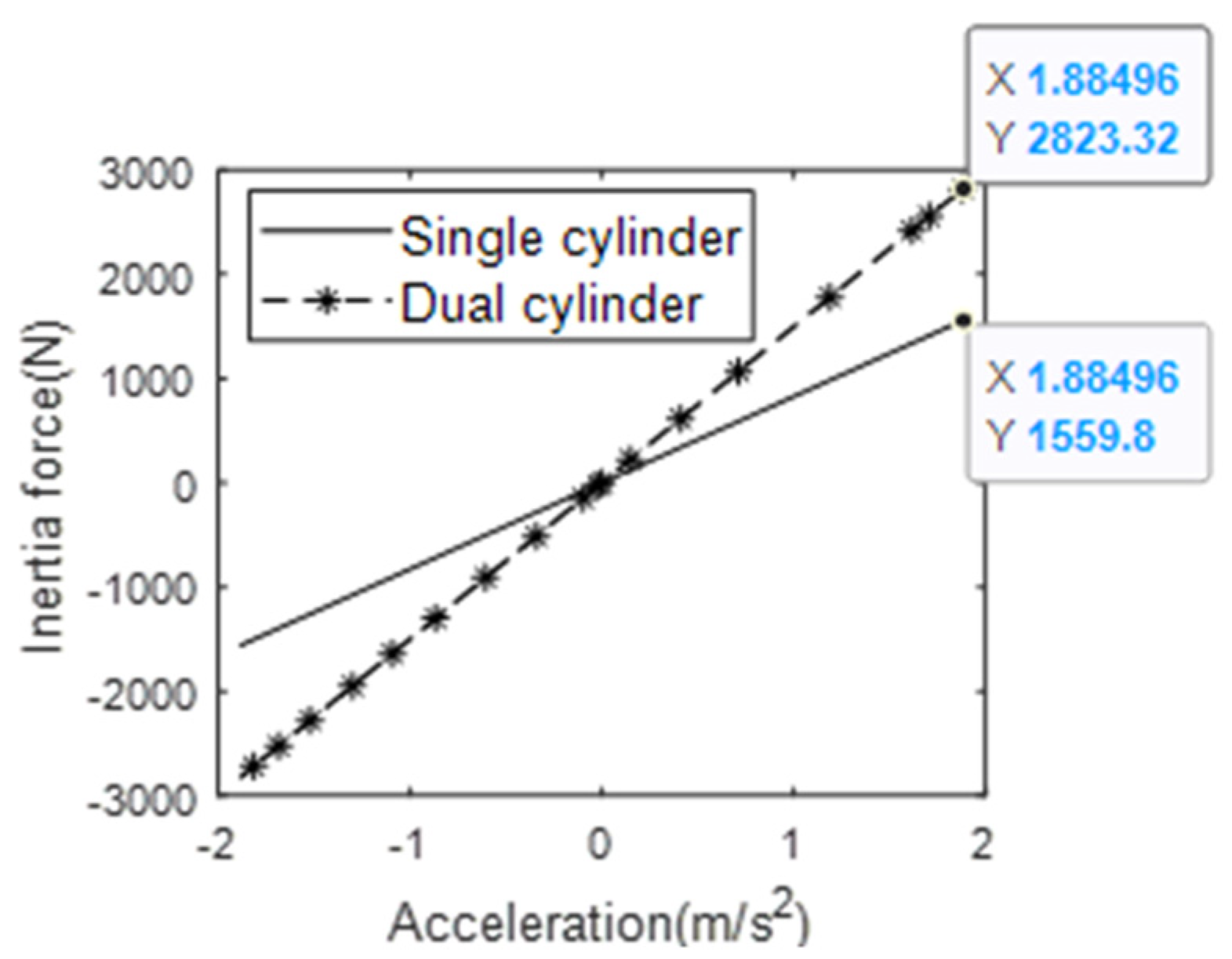
As can be seen from Figure 8 and Figure 9, the maximum damping force of a dual-cylinder fluid inerter is 40.32% (5451/13,519 = 0.4032) of that in a single-cylinder fluid inerter, and the inertia force is 180.96% (2823/1560 = 1.8096).

5. Bench Test

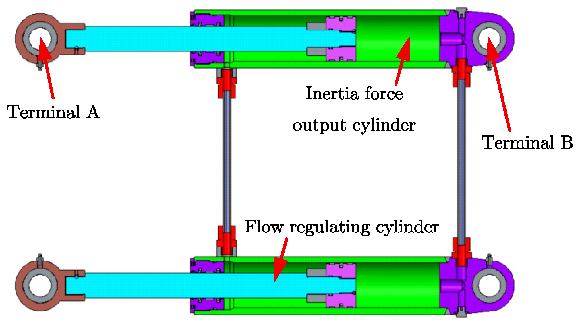
According to the structural parameters shown in Table 1, a dual-cylinder fluid inerter prototype is produced. We adopt two hydraulic cylinders of the same size; one is the inertia force output cylinder, the other is the flow-regulating cylinder. We use hydraulic pipeline to connect the main chambers and annular chambers of the two cylinders, respectively, as shown in Figure 10.
Sinusoidal speed signals of different frequencies are loaded into the fluid inerter, and signals such as time, displacement, and load at both terminals are collected. The specific operation is as follows: Connect hinge A (terminal 16) and hinge B (terminal 1) of the inertia force output cylinder with the base and exciter of the test bench, respectively, as shown in Figure 11. Connect the pipe and inject water, as shown in Figure 12.
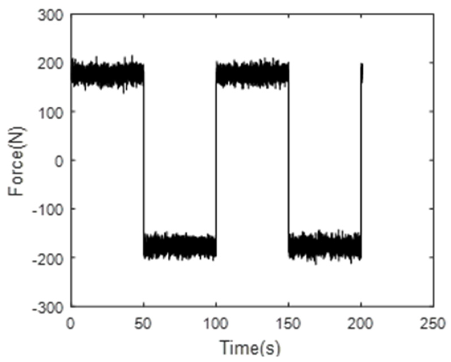
Figure 13 shows the output force curves at both terminals of the dual-cylinder inerter when the quasi-static sinusoidal speed signal of 0.01 Hz is used as the input. According to the statistics, the average of the absolute value of F: F ¯ = 178 N, and the approximate value of friction force Ff can be obtained by combining Formula (8).
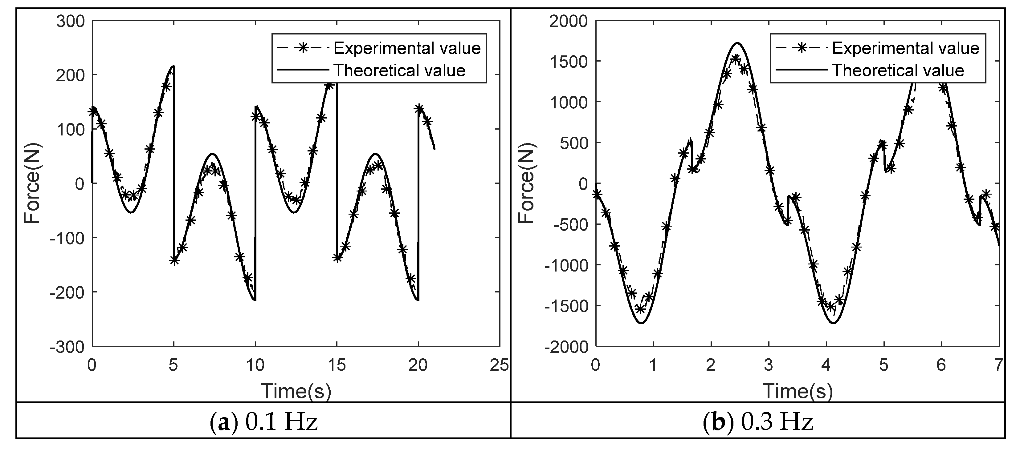
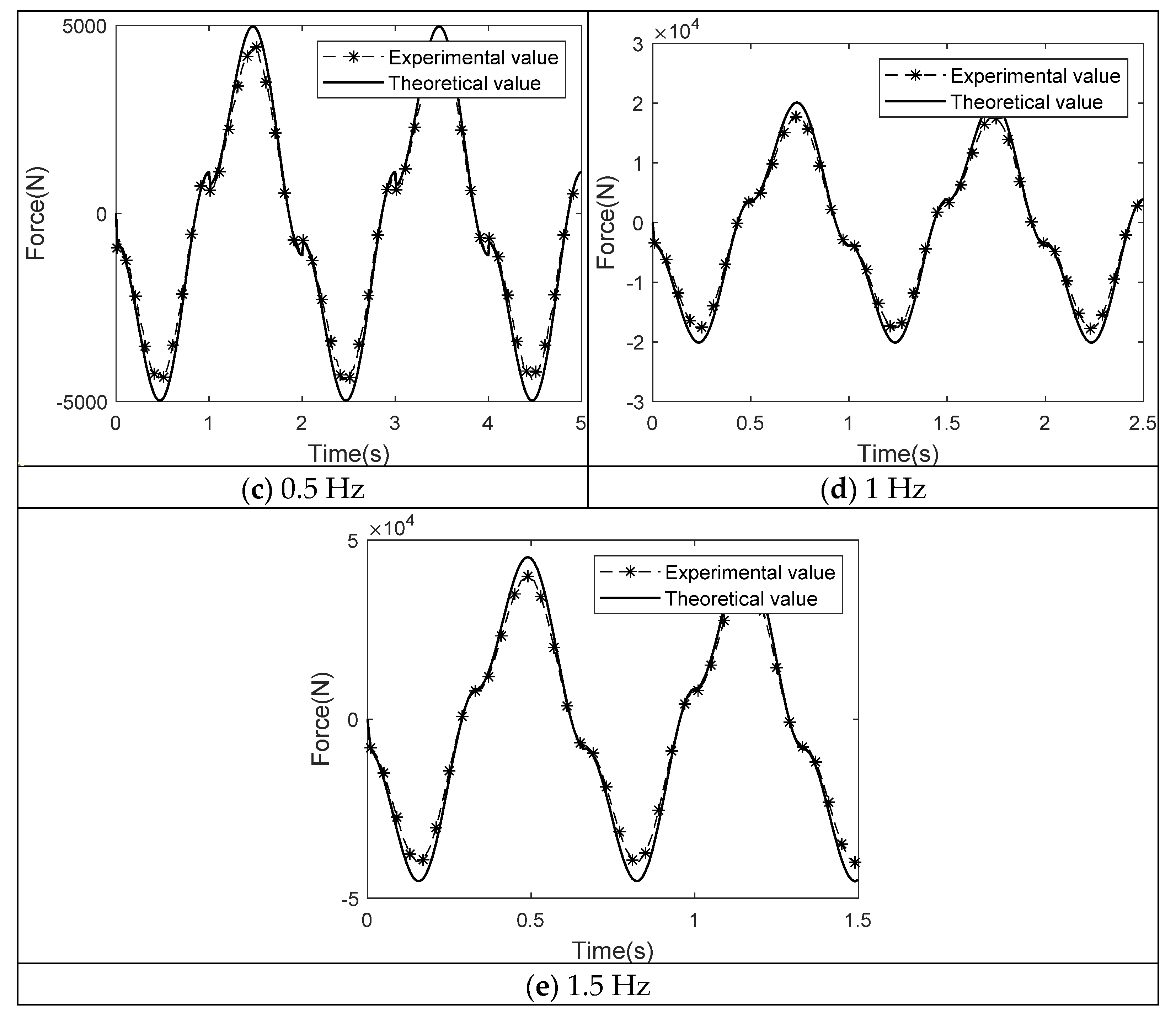
As can be seen from Figure 14 and Table 4, as the frequency increases, the deviation between the experimental value and the theoretical value becomes smaller and smaller, and the variation trend and value of the experimental value and the theoretical value are highly consistent. The mechanical model established in this paper can guide the structural design and parameter-optimization of dual-cylinder fluid inerters.

6. Conclusions

Through the principal analysis, mechanical-characteristics modeling, and bench test of a dual-cylinder fluid inerter, the following conclusions are drawn:
(1) Dual-cylinder fluid inerters exists in theory, are feasible in principle, and can be achieved with engineering.
(2) Compared with single-cylinder fluid inerters, the damping force of dual-cylinder fluid inerters is significantly reduced, with 40.32% of the single-cylinder fluid inerter, and the inertia force is significantly increased, with 180.96% of the single-cylinder fluid inerter.
(3) The mechanical model established in this paper can effectively simulate the mechanical properties of a dual-cylinder fluid inerter, and can guide its structural design and parameter-optimization.
(4) Dual-cylinder fluid inerters can provide greater inertial force, and have great potential in vehicle suspensions, building vibration reduction, and other applications.

Author Contributions

Conceptualization, F.D.; methodology, F.D.; Software, C.W.; Validation, W.N.; Formal analysis, F.D.; Investigation, C.W.; Resources, C.W.; Data curation, W.N.; Writing—original draft preparation, F.D.; Writing—review and editing, F.D.; Supervision, F.D.; Project administration, F.D. All authors have read and agreed to the published version of the manuscript.

Funding

National Natural Science Foundation of China (51875536) and Fengtai District science and technology Nova program (Kjxx202005).

Institutional Review Board Statement

Not Applicable.

Informed Consent Statement

Not Applicable.

Data Availability Statement

Not Applicable.

Conflicts of Interest

The authors declare no conflict of interest.

References

  1. Smith, M.C. Synthesis of mechanical networks: The inerter. IEEE Trans. Autom. Control 2002, 47, 1648–1662. [Google Scholar] [CrossRef] [Green Version]
  2. Shen, Y.; Chen, L.; Liu, Y. Analysis of vibration isolation performance of vehicle suspension with nonlinear fluid inerter. Automot. Eng. 2017, 39, 789–795. [Google Scholar]
  3. Du, F.; Mao, M.; Chen, Y. Structure design and performance analysis of inerter-spring-damper suspension based on dynamic model and parameter optimization. J. Vib. Shock 2014, 33, 59–65. [Google Scholar]
  4. Lazar, I.F.; Neild, S.A.; Wagg, D.J. Using an inerter-based device for structural vibration suppression. Earthq. Eng. Struct. Dyn. 2014, 43, 1129–1147. [Google Scholar] [CrossRef] [Green Version]
  5. Giaralis, A.; Petrini, F. Wind-induced vibration mitigation in tall buildings using the tuned mass-damper-inerter. J. Struct. Eng. 2017, 143, 04017127. [Google Scholar] [CrossRef]
  6. Wen, H.; Guo, J. Performance Analysis of Habitual Capacity Vibration Isolation System and Exploration of Its Application in Ship-Sea Field; National Defence Industry Press: Beijing, China, 2018; pp. 1–20. [Google Scholar]
  7. Lazar, I.F.; Neild, S.A.; Wagg, D.J. Vibration suppression of cables using tuned inerter dampers. Eng. Struct. 2016, 122, 62–71. [Google Scholar] [CrossRef] [Green Version]
  8. Xu, K.; Bi, K.; Han, Q. Using tuned mass damper inerter to mitigate vortex-induced vibration of long-span bridges: Analytical study. Eng. Struct. 2019, 182, 101–111. [Google Scholar] [CrossRef]
  9. Jiang, J.Z.; Matamoros-Sanchez, A.Z.; Goodall, R.M.; Smith, M.C. Passive suspensions incorporating inerters for railway vehicles. Veh. Syst. Dyn. 2012, 50 (Suppl. S1), 263–276. [Google Scholar] [CrossRef]
  10. Li, Y.; Jiang, J.Z.; Neild, S. Inerter -based configurations for main-landing-gear shimmy suppression. J. Aircr. 2016, 54, 684–693. [Google Scholar] [CrossRef] [Green Version]
  11. Robin, T. Fluid Inerter: EP. EP2528757A1, 5 December 2012. [Google Scholar]
  12. Swift, S.J.; Smith, M.C.; Glover, A.R. Design and modelling of a fluid inerter. Int. J. Control 2013, 86, 2035–2051. [Google Scholar] [CrossRef]
  13. Deastra, P.; Wagg, D.J.; Sims, N.D. The realisation of an inerter-based system using fluid inerter. In Dynamics of Civil Structures; Springer: Cham, Switzerland, 2019; Volume 2, pp. 127–134. [Google Scholar]
  14. Tipuric, M.; Deastra, P.; Wagg, D. Semi-active inerters using magnetorheological fluid: A feasibility study. In Active & Passive Smart Structures & Integrated Systems XII, Proceedings of the SPIE Smart Structures and Materials + Nondestructive Evaluation and Health Monitoring, Denver, CO, USA, 4–8 March 2018; SPIE: Bellingham, WA, USA, 2018. [Google Scholar]
  15. Liu, X. Fluid Inerter Based Vibration Suppression: Modelling Methodology. Ph.D. Thesis, University of Bristol, Bristol, UK, 2019. [Google Scholar]
  16. Wang, L.; Mao, M.; Lei, Q.; Chen, Y.; Zhang, X. Modeling and testing for a hydraulic inerter. J. Vib. Shock 2018, 37, 146–152. [Google Scholar]
  17. Shen, Y.; Liu, Y.; Chen, L. Optimal design and experimental research of vehicle suspension based on a hydraulic electric inerter. Mechatronics 2019, 61, 12–19. [Google Scholar] [CrossRef]
  18. Du, F.; Yang, Y.; Wang, Y. Dual Cylinder Fluid Inerter. CN113719572A, 30 November 2021. [Google Scholar]
  19. Wu, W. Fluid Mechanics; Peking University Press: Beijing, China, 2018. [Google Scholar]
  20. Dixon, J.C. The Shock Absorbe Handbook; Professional Engineering Publishing Ltd.: London, UK; John Wiley & Sons Ltd.: Chichester, UK, 2007. [Google Scholar]
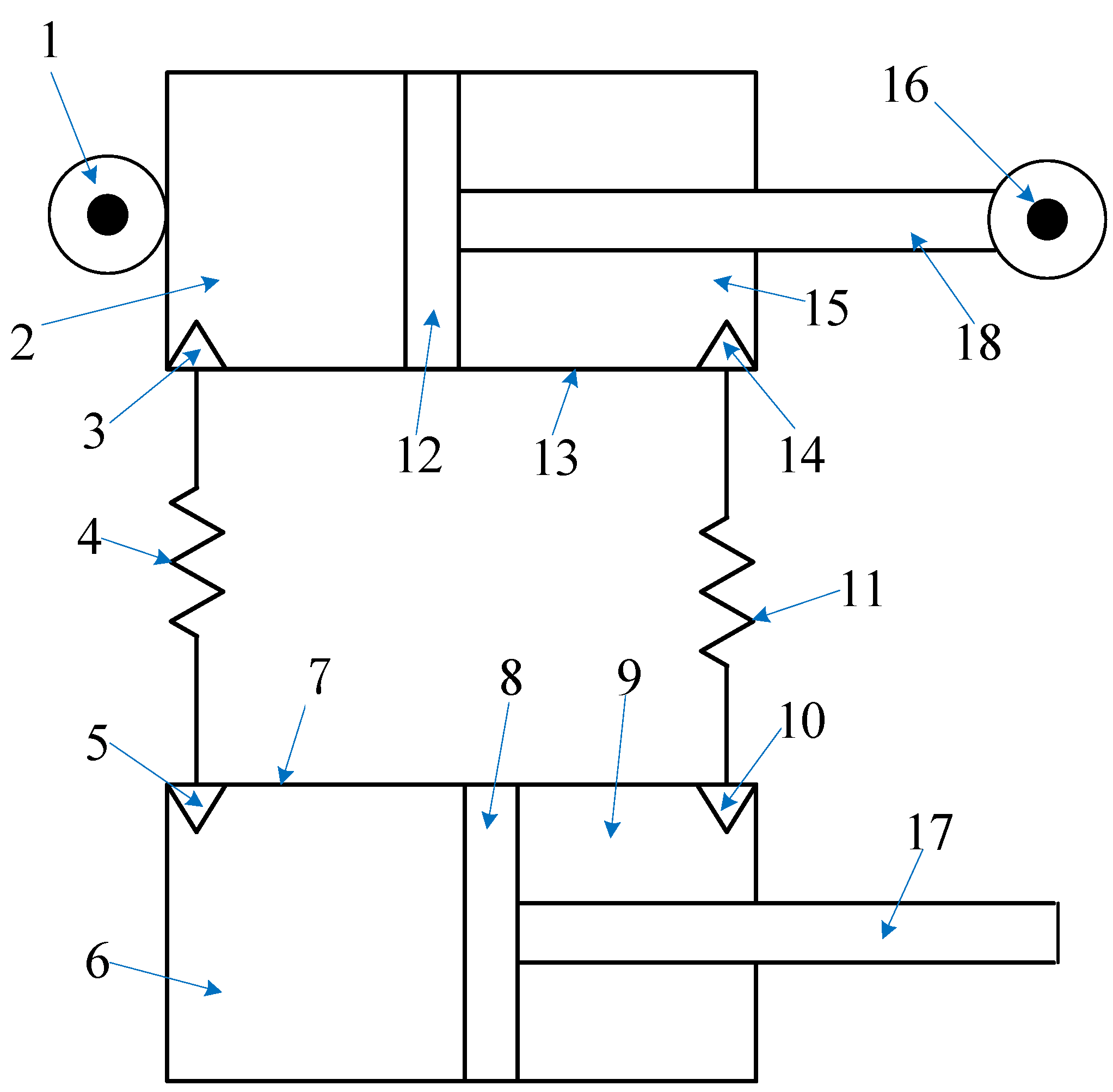
Figure 1. Schematic drawing of dual-cylinder fluid inerter. 1—terminal; 2—main chamber; 3—oil port; 4—pipeline; 5—oil port; 6—main chamber; 7—cylinder; 8—piston; 9—annular chamber; 10—oil port; 11—pipeline; 12—piston; 13—cylinder; 14—oil port; 15—annular chamber; 16—terminal; 17—piston rod; 18—piston rod.
Applsci 12 10849 g001
Figure 2. The curve of damping and inertia force of a dual-cylinder fluid inerter.
Applsci 12 10849 g002
Figure 3. The curve of damping force and velocity.
Applsci 12 10849 g003
Figure 4. The curve of inertia force and acceleration.
Applsci 12 10849 g004
Figure 5. The comparison curve between theoretical model and pipe module in Simulink.
Applsci 12 10849 g005
Figure 6. The relationship between inertance and L4.
Applsci 12 10849 g006
Figure 7. The curve of damping and inertia force over time of a single-cylinder fluid inerter.
Applsci 12 10849 g007
Figure 8. The comparison curve of damping force and velocity.
Applsci 12 10849 g008
Figure 9. The comparison curve of inertia force and acceleration.
Applsci 12 10849 g009
Figure 10. Drawing of the dual-cylinder fluid inerter.
Applsci 12 10849 g010
Figure 11. Prototype of dual-cylinder fluid inerter.
Applsci 12 10849 g011
Figure 12. Test layout of dual-cylinder fluid inerter.
Applsci 12 10849 g012
Figure 13. The force value of 60 mm and 0.01 Hz.
Applsci 12 10849 g013
Figure 14. The force value of 60 mm at different frequencies.
Applsci 12 10849 g014aApplsci 12 10849 g014b
Table 1. Table of structure and fluid parameters of the single-cylinder fluid inerter.
Structure Size
Diameter of main chamber cylinder 2D2(mm)80
Diameter of main chamber cylinder 6D6(mm)80
Diameter of piston rod 18D18(mm)50
Diameter of piston rod 17D17(mm)50
Diameter of pipeline 4D4(mm)12
Diameter of pipeline 11D11(mm)12
Length of pipeline 4L2 (mm)5000
Length of pipeline 11L11 (mm)5000
Parameters of the Fluid Medium
Fluid typewater
Densityρ(kg/m3)1000
Dynamic viscosityµ (cSt)1
Input Signal Parameters
Input typesinusoidal velocity signal
Amplitude (mm)60
Frequencyω(Hz)1
Table 2. Table of result.
InertanceResult
Inertance generated by pipeline 4B4 (kg)1115
Inertance generated by pipeline 11B11 (kg)412
The total inertanceB(kg)1527
Table 3. Table of structure and fluid parameters of the dual cylinder fluid inerter.
Structure Size
Diameter of cylinder (mm)80
Diameter of piston rod (mm)50
Diameter of pipe (mm)12
Length of pipeline (m)10
Parameters of the Fluid Medium
Fluid typeWater
Densityρ(kg/m3)1000
Dynamic viscosityµ(cst)1
Result
Inertance (kg)828
Table 4. Table of theoretical and experimental force values.
Frequency (Hz)Max of Experimental Value (kN)Max of Simulation Value (kN)Size Error (%)
0.10.240.21311.25
0.31.681.838.93
0.54.554.887.25
119.3220.164.35
1.545.4347.13.68
Note: Size error = max of experimental value max of simulation value max of experimental value × 100 % .
Publisher’s Note: MDPI stays neutral with regard to jurisdictional claims in published maps and institutional affiliations.