Abstract
The support theory of the excavation disturbance zone (EDZ) cannot provide an accurate physical explanation or theoretical description of the time-dependent properties required for the development of an EDZ. Therefore, the primary factors that cause the formation of an EDZ should be determined to further improve the support theory of the EDZ and grasp the principle underlying the control of the long-term stability of rock masses. Considering the headrace tunnel and nuclear waste repository as the research background, this study aimed to understand the deformation damage evolution process of the surrounding rock after tunnel excavation under different working conditions using the self-developed realistic failure process analysis (RFPA2D) code. The simulation revealed the following. First, an EDZ is formed, although the deformation damage to the surrounding rock is relatively small under the action of environmental factors. Second, under the action of stress in the abovementioned case, the deformation speed, damage degree, and scope of the surrounding rock significantly increase, accelerating the formation and development of the EDZ. Therefore, the boundary of the EDZ expands significantly. Third, when environmental factors are blocked, the range of the EDZ is small due to the small deformation damage to the surrounding rock. Thus, the main factors responsible for the formation of the EDZ are environmental factors, whereas stress is only an auxiliary factor. A numerical simulation method that considers environmental factors can more accurately reproduce the formation of an EDZ. Therefore, a study of the internal mechanism of the EDZ phenomenon can provide a more in-depth understanding of the essential characteristics of an EDZ at the macro level. Furthermore, it can provide a scientific basis and method for the construction and support designs of underground excavation projects and widen the possibilities for further improving the support theory of the EDZ.
1. Introduction
In rock mass engineering, which includes coal mining, deep foundation pit construction, slope excavation, traffic, hydraulic tunnels, and underground cavern excavation, excavation disturbances generally cause the loosening of the surrounding rock at a certain depth. Thus, the concept of excavation disturbance/damage zone (EDZ) and the related support theory of the EDZ were developed [1,2,3,4,5]. Due to the continuous deep mining of coal mines and the construction of large water conservation and hydropower projects as part of the Western Development in China policy, the complex rock masses involved exhibit EDZ characteristics (e.g., Xiaowan [6], Jinping I [7], and II hydropower stations [8]). These underground projects are subject to a core problem associated with maintaining the stability of the rock mass around the excavation space. The depth of an EDZ is a critical parameter for the analysis of the stability of the surrounding rock, calculation of the rock mass load, and determination of the range and thickness of bolt-shotcrete, in addition to the lining support mode. Therefore, it is necessary to study the main driving forces and formation processes of an EDZ.
Outside China, the EDZ is generally referred to as the range in which the surrounding rock caused by excavation is loosened. Research on EDZs was initiated in the early 20th century. However, EDZs were comprehensively and systematically studied only in the 1980s, during which the HRL Lab, Sweden SKB, URL Lab of AECL, Canada [9], and JAEA, Japan, reported significant findings. Although several studies have investigated the causes of EDZ formation and reported significant results, their conclusions differ. Several researchers have reported that stress is the main cause of EDZ formation. Field measurement results demonstrate that the stress redistribution caused by excavation promotes the continuous initiation and expansion of microcracks and the gradual formation of a fracture network in the surrounding rock, which eventually leads to the formation of the EDZ. The influence of stress redistribution on the depth of an EDZ is greater than that of other factors [10,11,12]. Three regions generally exist around a cavern, and they are generally related to stress-induced damage, as detailed in several studies and monographs on EDZs; i.e., stress disturbance dominates the formation of these three regions [13,14]. In addition, empirical methods [15,16] or numerical simulations [17,18,19,20] for predicting the depth of an EDZ in brittle rock masses have been used based on the damage range caused by the stress concentration. Several researchers have reported that the formation of an EDZ is the result of a joint dominance of stress conditions, excavation methods, and other factors. They performed on-site monitoring, numerical calculations, and additional research on the EDZ. The research results revealed that the formation of the EDZ in underground caverns is mainly caused by stress redistribution and excavation damage, and a few studies have considered weathering or water-rock interactions [5,21,22]. To an extent, the above-mentioned research results provide an improved understanding of the concept and formation causes of the EDZ and can serve as a basis for excavation scheme design and safe construction in underground rock engineering. Furthermore, the results promote further research on the formation mechanism and support theory of the EDZ.
In China, the EDZ is referred to as the broken rock zone. The concept and related support theory was first studied in the late 1970s. Dong Fangting performed several ultrasonic tests in the Zhuxianzhuang coal mine and reported a sound wave velocity reduction zone around the roadway, which exhibited high regularity. Based on the mechanism analysis of the sound wave test, the sound wave velocity reduction zone was considered a fractured zone referred to as an EDZ. Subsequently, the support theory of the EDZ was established based on this test result. A significant amount of related research was conducted based on the consensus that stress is the fundamental cause of the formation of an EDZ. In terms of numerical calculations, several researchers have clarified the related mechanism of EDZ formation based on their predictions of the EDZ under different geostress states using numerical calculation software tools [23]. Furthermore, the significant influence of stress redistribution on an EDZ has been determined in several studies that simulated the entire process, from underground cavern excavation to the formation and gradual evolution of EDZs [24,25,26]. In terms of theoretical analysis, a criterion for determining the depth of the EDZ was proposed based on damage theory and a two-line damage model [27]. In terms of the combination of theoretical analysis and engineering practice, the depth of an EDZ is generally determined by stress calculation or using the fractal geometric theory. The theoretical results are thereafter compared with field measurement results [28,29]. In addition, there are alternative perspectives on the causes of EDZ formation. For example, several researchers have reported that the formation of the EDZ is significantly influenced by geological conditions and excavation steps [30]. However, it has been highlighted that the ground stress magnitude, lateral coefficient, and support resistance considerably influence the formation of the EDZ [31]. Furthermore, several researchers have highlighted that the excavation method is a significant contributing factor to the formation of the EDZ during tunnel excavation, particularly under low in-situ stress conditions [32,33]. The above-mentioned research findings improve the understanding of the EDZ based on the discussion of the formation mechanism of an EDZ, the proposal of effective methods for detecting the depth of an EDZ, and the development of a relatively complete support theory of the EDZ, which have contributed significantly to underground geotechnical engineering.
There is a consensus on the existence of the EDZ based on previous research. Although there are multiple descriptions of the EDZ, the underlying characteristics are the same. Generally, an EDZ is defined as a zone of surrounding rock fracture induced by stress adjustment. However, the formation mechanism and support theory of the EDZ require further clarification, which indicates that the above-mentioned studies are limited. For example, the formation process of the EDZ has time-dependent properties, and an EDZ and its actual depth under low confining pressure cannot be simulated using mechanical loading. Hence, in this study, a single-factor control variable method was used to understand the EDZ in high-humidity and high-temperature environments, respectively. Firstly, based on the basic parameters of a headrace tunnel, three numerical models under different working conditions were established using the realistic failure process analysis (RFPA2D)-humid code [8,34], which introduced numerical algorithms of the humidity–stress–damage coupling model. The mechanical property changes of the surrounding rock, deformation characteristics, and damage evolution process of the surrounding rock under three different working conditions were compared and analyzed. Secondly, based on the basic parameters of a nuclear waste repository, the RFPA2D-thermal code [35,36,37,38,39], which introduced numerical algorithms of the thermo-mechanical coupling model with damage evolution, was adopted to simulate the dynamic evolution process of the surrounding rock mechanical behavior after tunnel excavation under three different working conditions. Subsequently, the deformation strength characteristics and damage evolution process of the surrounding rock under each working condition were comprehensively analyzed. The corresponding simulation results were then compared. Finally, based on the numerical simulation results in the above-mentioned cases, several phenomena involved in the formation process of an EDZ, which require further clarification, were analyzed to determine the main driving forces for the formation of the EDZ.
2. Numerical Methodology
Based on the RFPA2D code, the RFPA2D-humid code and RFPA2D-thermal code were developed by introducing numerical algorithms of the humidity–stress–damage coupling model and thermo-mechanical coupling model with damage evolution, respectively. The core parts of the two codes are described below.
2.1. Humidity–Stress–Damage Coupling Model
The movement of water in a porous material generally conforms to Fick’s law [40,41,42]. The use of the diffusion equation to describe the behavior of humidity diffusion can more accurately reflect the variation in humidity in the surrounding rock with respect to time and space. If the influence of heat and gravity on moisture is not considered, the humidity diffusion equation can be expressed as follows:
where h is the relative humidity, Dh is the humidity diffusion coefficient, and t represents time.
The humidity variable h obtained using Equation (1) is a function of space and time. Equation (1) can compensate for the deficiency in the existing theoretical models that cannot describe the humidity changes in rock masses.
Although water affects the deformation and fracture of rock under loading, the mechanical effect of water on rock is considered by the principle of effective stress. However, the influence of water on the physical properties of rocks (such as the strength and elastic modulus) has not received sufficient attention, and an understanding of the influence of humidity on the mechanical properties of rock is relatively lacking. Consequently, the influence of humidity on the strength and elastic modulus was comprehensively considered in this study. The relationships between these two parameters and humidity can be expressed as follows [43,44]:
where E and E0 are the current and initial elastic moduli of rock, respectively; σc and σc0 are the current and initial strengths of rock, respectively; h represents the current relative humidity and hcri represents the critical humidity value. That is, when h is higher than hcri, the weakening effect of humidity on the material properties should be considered, otherwise, it can be neglected. In addition, ω and ξ are the degradation coefficients of the elastic modulus and strength with humidity variable h, respectively.
Damage occurs when an external load is applied to a rock. The RFPA2D-humid code classifies the damage in a meso-element as tensile or shear damage. The maximum tensile stress criterion is used as the threshold for tensile damage, and the Mohr–Coulomb criterion is used as the threshold for shear damage.
Tensile damage occurs when the tensile stress applied to an element exceeds its maximum tensile strength. In this case, the corresponding damage variable d can be expressed as follows [45,46]:
where γ is the residual strength coefficient of the element (0–1), i.e., λ = ftr/ft; ft represents the tensile strength of the element; ftr represents the residual strength of the damaged element; and εt0 represents the ultimate elastic strain, i.e., εt0 = ft/E0. Moreover, εtu represents the maximum tensile strain.
Shear damage occurs when the shear stress of an element is higher than its shear strength. In this case, the corresponding damage variable can be defined as follows [45,46]:
where γ is defined in the same manner as tensile damage, and εc0 is the maximum compressive principal strain, i.e., εc0 = fc/E0, and fc represents the compressive strength of the element.
The mechanical properties of the rock gradually weaken with humidity diffusion. Conversely, the weakened rock changes its diffusion properties. Simultaneously, the external load causes rock damage and further weakens the mechanical properties of the rock, thereby accelerating the diffusion of humidity. Coupling can be observed between humidity, stress, and damage. This coupling is mainly expressed using the diffusion coefficient and damage variable, whereas the relationship between the humidity diffusion coefficient and damage can be expressed as follows [45]:
where Dh0 represents the initial humidity diffusion coefficient of rock; and dc represents a critical damage value, i.e., when the damage reaches dc, the humidity diffusion coefficient instantaneously increases to a constant value Dhc. Here, Dhd represents the humidity diffusion coefficient when the element is first damaged, and η represents the diffusion mutation coefficient.
In addition, an increase in humidity causes the rock mass to swell; conversely, the rock mass exhibits a shrinking effect. Therefore, the constitutive law of the rock mass with the humidity effect can be expressed as follows [45]:
where I is the unit vector; λ and μ are Lamé constants; and εh is the humidity swelling (shrinkage) strain, which can be expressed as a linear function of humidity, as follows:
where αh is the humidity swelling (shrinkage) coefficient and ht and h0 are the relative humidity values at time t and the initial time, respectively.
The expressions above constitute the humidity-stress-damage coupling model, which is the core part of the RFPA2D-humid code. To verify the feasibility of the RFPA2D-humid code, Tang et al. conducted experiments and compared the experimental results with the numerical results [8]. First, a creep test of the sandstone samples under a high-humidity environment was carried out in the laboratory. As shown in Figure 1, the dry sample was placed on the base of a sealed container with a high-stiffness stainless steel bottom and glass walls. Water was injected into the container until the top of the specimen was submerged, and then a constant load was applied to the specimen to conduct a uniaxial creep test. Thereafter, a numerical simulation was carried out under the same conditions as the creep test. The creep behaviors obtained from the experiment and numerical simulation are shown in Figure 1. As can be observed from the figure, the two curves are highly similar, indicating the reliability of the numerical method employed.
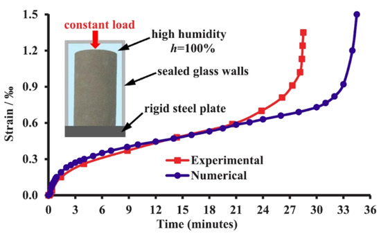
Figure 1.
Creep behaviors of sandstone obtained from experimental and numerical results under the same conditions in a high-humidity environment [8].
In addition, using this numerical method, Tang et al. conducted a simulation study on a case (headrace tunnel in this study), in accordance with the actual on-site conditions, and obtained the deformation curve of the tunnel surrounding rock with time [8]. Figure 2 presents a comparison of the results between the field measurement and numerical simulation. As can be seen from the figure, there was good agreement between both sets of results, which further confirms the feasibility of the numerical method employed.
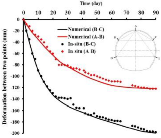
Figure 2.
Comparisons of the deformation of the surrounding rock between field measurements and numerical simulations under a high-humidity environment [8].
2.2. Thermo-Mechanical Coupling Model with Damage Evolution
In the case of thermal transients, thermodynamic equilibrium in the material domain conforms to Fourier’s law [47,48]. Therefore, the temperature distribution in the rock can be expressed as follows:
where κ represents the thermal conductivity, subscripts x and y represent the coordinates, T represents the temperature, Q is the heat source, and ρ and c denote the density and specific heat of the material, respectively.
The description of rock damage in the RFPA2D-thermal code is the same as that in the RFPA2D-humid code, i.e., the damage variable can be expressed using Equation (4) or Equation (5). Heat conduction forms a temperature stress field. The external load causes rock damage and changes the mechanical properties of the rock, thereby influencing heat conduction. Coupling can be observed among the temperature, stress, and damage, which can be mainly described with respect to the thermal conductivity, damage variable, and temperature. Furthermore, a correlation can be observed between these three parameters, which can be expressed in different ways depending on the type of rock damage [36]. When tensile damage occurs in a rock, the relationship between the three parameters is expressed as Equation (10); conversely, when shear damage occurs in a rock, the relationship between them is expressed as in Equation (11).
where κ0 is the initial thermal conductivity; and a and b are empirical parameters, such as the experimental results of several lithologies such as crystalline rock and sedimentary rock, as reported in the literature [49]. Moreover, ξ1 (ξ1 < l) represents the thermal conductivity mutation coefficient.
The influence of heat on a rock mass is similar to that of humidity on a rock mass; therefore, the constitutive law of rock mass with thermal effect can be expressed as follows [36]:
where Dijkl is the elasticity tensor, β is the thermal expansion coefficient, and δij is the Kronecker constant.
The variation in the specific heat of an element in the model can be expressed as follows [36]:
where c0 is the specific heat at 0 °C and ψ is the impact factor, which is generally 3 × 10⁻³/°C.
The expressions above constitute the thermo-mechanical coupling model with damage evolution, which is the core part of the RFPA2D-thermal code. To verify the accuracy of the RFPA2D-thermal code, Tang et al. compared the results of theoretical analysis with those of numerical calculation [37]. First, as shown in Figure 3, a calculation model consisting of two concentric circles was established. In the model, a and b represent the radii of the embedded particles and matrix, respectively, and g and m represent the embedded particles and matrix, respectively. It should be noted that the application of an initial temperature to the model would lead to thermal stress due to the different thermal expansion coefficients of the internal and external media, which would then induce continuous changes in the thermal stress of the model due to uniform heating. Finally, two methods of theoretical analysis and numerical calculation were used to solve the thermal stress in the model respectively. Figure 4 presents a comparison of the results of the theoretical analysis and numerical calculation. As can be seen from the figure, there was good agreement between both sets of results, thus indicating the reliability of the numerical method employed.
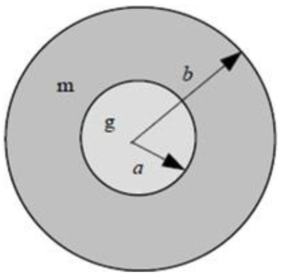
Figure 3.
Two-concentric-circle model [37].
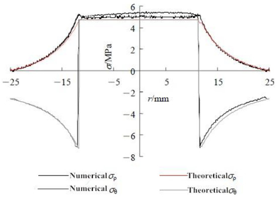
Figure 4.
Stress distributions with theoretical and numerical solutions [37].
In addition, using this numerical method, Li et al. conducted a simulation study on a case (nuclear waste repository in this study) in accordance with the actual on-site conditions [36]. The damage and failure process of the surrounding rock obtained from the numerical simulation was consistent with the actual on-site conditions. Moreover, the final failure depth was close to that reported using different research methods, which further verified the feasibility of the numerical method employed.
3. Influence of Humidity Factor
3.1. Model Establishment
To explore the influence of humidity diffusion on the formation process of the EDZ, considering the diversion tunnel of Jinping II Hydropower Station as the engineering background, three working conditions were designed to simulate the deformation and damage evolution process of the surrounding rock. First, the tunnel was in a humid environment and unloaded. Second, the tunnel was subject to the combined action of load and water. Third, although the tunnel was subject to the combined action of load and water, waterproofing measures were taken. The model size for the three working conditions was 66 m × 66 m, which was divided into 435,600 elements. The semicircular arch tunnel was located at the center of the model, and its size was 6 m × 6.25 m (width × height). Points A and C were located in the middle of the roof and floor of the tunnel, respectively, and point B was located in the middle of the left sidewall of the tunnel. The points were used to observe or measure the deformation of the rock mass at their respective positions, as shown in Figure 5. Under the second and third conditions, the bottom boundary of the model was fixed, a lateral compressive stress of 1.3 MPa was applied to the left and right sides, and a vertical compressive stress of 5.2 MPa was applied to the top. The plane strain model was adopted for all the models. The air humidity of the tunnel was 100%, the initial rock mass humidity was 20%, and the thickness of the waterproof layer was 30 cm. It should be noted that a humidity of 100% always saturates the rock mass, which is an environmental factor introduced into this model. The physical and mechanical parameters of the materials are listed in Table 1.
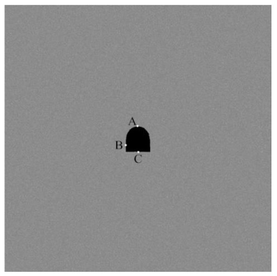
Figure 5.
Numerical calculation model.

Table 1.
Physical and mechanical parameters of numerical simulation of humidity.
3.2. Analysis of Simulation Results
3.2.1. No-Load Condition
The processes of humidity diffusion, elastic modulus degradation, stress field change, and damage evolution within 150 days after tunnel excavation without an external load in a high-humidity environment are shown in Figure 6. At the initial stage, the humidity in the environment disturbed the surrounding rock only on the surface of the excavated space (Figure 6(a1)). Over time, the moisture at the surface gradually migrated into the interior of the surrounding rock. Subsequently, a humidity gradient was formed, which gradually decreased from the surface of the tunnel to the deep surrounding rock (Figure 6(a2,a3)). Due to the weakening effect of water on the mechanical properties of the rock, the elastic modulus and strength of the surrounding rock decreased. Moreover, with an increase in the water content, the weakening effect became more significant. Therefore, the decrease in the elastic modulus and strength of the surrounding rock exhibited a gradient effect. That is, the rock mass strength and elastic modulus of the tunnel surface were minimal, and the strength and elastic modulus of the surrounding rock gradually increased with depth. The strength and elastic modulus of the rock mass, which was not influenced by moisture diffusion, were unchanged (Figure 6(b1–b3)). Simultaneously, stress was observed in the region of diffused humidity, with an increase in the humidity, the stress value increased (Figure 6(c1–c3)). This is mainly because of the presence of a humidity gradient that generates a humidity stress field. In addition, the reduction in the elastic modulus increases the deformation capacity of the surrounding rock, whereas a reduction in strength renders the surrounding rock more vulnerable to destruction. When the humidity spreads to a certain depth in the surrounding rock, the bearing capacity of the surrounding rock is weakened due to the decrease in its strength over a large range. Subsequently, the surrounding rock is damaged under stress. Figure 6(d1–d3) presents the progressive damage process of the surrounding rock, where the position of the circle indicates the occurrence of micro-damage, and the size of the circle represents the amount of energy released by the micro-damage. Initially, damage mainly occurs in the sidewall and corner of the rock mass on the surface of the tunnel (Figure 6(d2)). As the humidity spreads to the deep surrounding rock, the damage gradually extends to the floor and depth of the surrounding rock; however, the overall damage is not significant (Figure 6(d3)). The mechanical property degradation and additional deformation of the surrounding rock, induced by the continuous diffusion of water into surrounding rock over time, are related to time and space. In summary, an EDZ with time-dependent properties could be formed even under no-load conditions, and humidity is a driving force for the formation of the EDZ under such conditions.
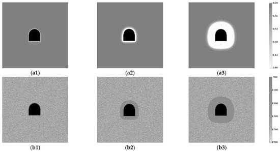
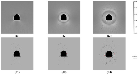
Figure 6.
Distributions of the relative humidity (a1–a3) (unit: 100%), elastic modulus degradation (b1–b3) (unit: MPa), shear stress (c1–c3) (unit: MPa) and damage (d1–d3) (unit: J) during the diffusion of humidity. The circle in the figure represents acoustic emission, and its size indicates how much energy is released.
3.2.2. Load Condition
Figure 7 and Figure 8 present the evolution processes of humidity, elastic modulus, and damage during humidity diffusion with and without the waterproofing layer within 150 days after the tunnel excavation under loading, respectively. After tunnel excavation, the surrounding rock was exposed to external high-humidity conditions, which caused the humidity level on the surface of the surrounding rock to exceed that in the interior of the surrounding rock. Over time, the moisture gradually migrated into the interior of the surrounding rock, thus resulting in the deterioration of the mechanical properties and the corresponding additional deformation of the surrounding rock, which in turn caused damage and led to the formation of the EDZ. As can be seen from Figure 7 and Figure 8, the weakened zones of the mechanical properties of the surrounding rock and failure zone increased continuously with an increase in the humidity diffusion range. However, there were several differences in their development processes. The weakened zone of mechanical properties of the surrounding rock evenly expanded around the tunnel wall. The failure zone was initially mainly distributed in the corner and sidewall of the tunnel and then gradually extended to the interior of the surrounding rock and tunnel floor.
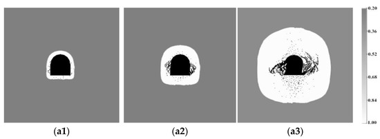
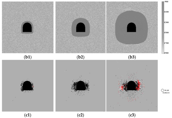
Figure 7.
Distributions of the relative humidity (a1–a3) (unit: 100%), elastic modulus degradation (b1–b3) (unit: MPa), and damage (c1–c3) (unit: J) during the diffusion of humidity without waterproofing.
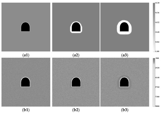
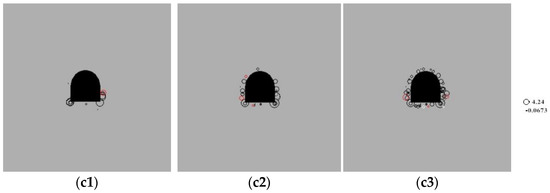
Figure 8.
Distributions of the relative humidity (a1–a3) (unit: 100%), elastic modulus degradation (b1–b3) (unit: MPa), and damage (c1–c3) (unit: J) during the diffusion of humidity with waterproofing. The circle in the figure represents acoustic emission, and its size indicates how much energy is released.
A comparison of the results in Figure 7 and Figure 8 suggests that timely waterproofing measures can significantly reduce the migration velocity and amount of moisture migrating into the interior of the surrounding rock after tunnel excavation, thereby significantly reducing the scope and degree of the weakened zone in terms of the mechanical properties of the surrounding rock. Simultaneously, the damage area and damage extent of the surrounding rock can be significantly reduced due to the reduction in the humidity stress, which is conducive to maintaining the stability of the tunnel. A comparison of Figure 6 and Figure 7 reveals that the depth of the EDZ is larger, and the surrounding rock damage is critical under the action of load. This is mainly because the load aggravates the damage of the weakened rock mass, and the generated cracks cause local stress concentration, which promotes the further expansion of cracks. Conversely, the development of cracks provides a migration path for moisture, which contributes to the further diffusion of moisture in the surrounding rock. Therefore, humidity diffusion and damage are interaction processes, which lead to the humidity–stress–damage coupling process. If the initial strength of the surrounding rock is low and waterproofing measures are not taken, the tunnel is particularly prone to collapse under the effects of both the load and humidity weakening action.
Figure 9 presents a comparison of the displacements of parts A, B, and C with and without the waterproofing layer within 150 days after tunnel excavation. In a tunnel with a high-humidity environment, the diffusion of humidity results in a large time-dependent deformation of the surrounding rock. The presence of humidity weakened the structure of the rock mass, which significantly influenced the stability of the tunnel. The roof, sidewall, and floor of the tunnel were significantly deformed. However, the influence of humidity on different parts of the tunnel varied, among which the sidewall deformation of the tunnel was the largest (560.39 mm), followed by that of the floor (210.25 mm), and the smallest was that of the roof (164.35 mm). Because moisture was mainly concentrated on the surrounding rock surface at the beginning of the excavation, the deformation of the tunnel caused by humidity was small. However, the humidity of the surrounding rock in the deeper range increased with the further diffusion of humidity, which caused the mechanical properties of the rock mass within a wider range to be weakened by the influence of moisture. In particular, the deformation of the surrounding rock further increased due to the degradation of the elastic modulus. When waterproofing measures were implemented immediately after tunnel excavation, the deformation of the surrounding rock in each part of the tunnel increased with time. However, the increment was small. The maximum deformations of the roof, sidewall, and floor of the tunnel were 4.28 mm, 11.43 mm, and 7.18 mm, respectively. Compared with the working conditions without the waterproofing layer, the deformation of corresponding parts of the tunnel were reduced by 160.07 mm, 548.96 mm, and 203.07 mm, respectively. Hence, the control effect of the waterproofing layer on the deformation of the surrounding rocks was significant. This is mainly because the extremely small humidity diffusion coefficient of the waterproof layer decreased the migration of water into the interior of the surrounding rock; thus, the area of the surrounding rock influenced by water was significantly small. Consequently, the amount of deformation of the surrounding rock was also extremely small. The simulation results under the two working conditions reveal that humidity is the main driving force for the formation of the EDZ. In addition, compared with Figure 2, before the tunnel instability, the deformation trend of the surrounding rock under the conditions without the waterproofing layer is generally consistent with the on-site monitoring results. In particular, the deformation of the surrounding rock exhibits a trend of initial gradual increase, followed by a rapid increase, and then a gradual increase. The only difference is that the deformation of the surrounding rock at the on-site finally tends to be stable, whereas the deformation of the surrounding rock increases abruptly at the end under the conditions without the waterproofing layer. This is mainly because the support measures were implemented on-site to effectively control the deformation of the surrounding rock; conversely, support measures were not implemented in the case of the tunnel without the waterproofing layer, resulting in the instability of the tunnel (numerical results). Evidently, the results obtained from the numerical simulation in this study were in good agreement with the actual on-site conditions to an extent, thus verifying the reliability of the results.
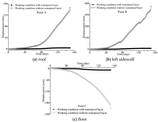
Figure 9.
Displacement at points A, B, and C (shown in Figure 1) during the diffusion of humidity under different working conditions.
4. Influence of Temperature Factor
4.1. Model Establishment
To explore the influence of heat conduction on the formation process of the EDZ, three working conditions were designed to simulate the deformation and damage evolution process of the surrounding rock respectively based on the in-situ scale test of the nuclear waste repository conducted by the Aspo Hard Rock Laboratory SKB in Sweden. The first condition involved an unloaded tunnel in a high-temperature environment. The second condition involved a tunnel subject to the combined action of a load and high temperature. The third condition involved the combined action of a load and high temperature, with insulation measures implemented. The model construction and boundary conditions were consistent with Figure 5, except that the environmental factor applied was not the humidity factor, but the temperature factor. The initial temperature of the rock mass was 15 °C. A high-temperature heat source of 200 °C was applied to the surface of the cavity, and the thickness of the insulation layer was 30 cm. It should be noted that a temperature of 200 °C can rapidly reduce the strength of the rock mass and cause irreversible damage, which is an environmental factor introduced into this model. The physical and mechanical parameters of the materials are listed in Table 2.
Table 2.
Physical and mechanical parameters of numerical simulation of temperature.
4.2. Analysis of Simulation Results
4.2.1. No-Load Condition
The processes of heat conduction, stress field change, and damage evolution within 150 days after tunnel excavation and without an external load in a high-temperature environment are shown in Figure 10. At the initial stage, the environmental temperature disturbed the surrounding rock only on the surface of the excavated space (Figure 10(a1)). Subsequently, the high-temperature tunnel surface gradually conducted heat into the interior of the surrounding rock; finally, a temperature gradient developed, in which the temperature gradually decreased from the surface of the tunnel to the deep surrounding rock (Figure 10(a2,a3)). The uncoordinated deformation of the rock mass caused by the temperature gradient produced constrained stress, thus forming a thermal stress field. Therefore, the presence of stress was observed in the region of heat conduction; with an increase in the temperature, the stress value increased (Figure 10(b1–b3)). Simultaneously, the temperature factor exhibited a weakening influence on the mechanical properties of the rock mass, particularly the strength of the rock mass. With an increase in the temperature, the deterioration rate of the mechanical properties of the rock mass increased. When the strength of the rock mass was lower than the acting stress, the rock mass was damaged. Therefore, the elements with low bearing capacity in the surrounding rock stress concentration zone of the tunnel surface were the first to be damaged and were mainly distributed in the sidewall and corner of the tunnel (Figure 10(c2)). With the high heat transfer to the interior of the surrounding rock, the damage gradually extended to the deep regions of the surrounding rock and tunnel floor; however, the overall damage was not significant (Figure 10(c3)). As the heat was continuously conducted to the deep regions of the surrounding rock over time, the surrounding rock damage caused by heat conduction (related to time) gradually extended to the surrounding space. In summary, an EDZ with time-dependent properties could be formed, even under no-load conditions. That is, the temperature is a driving force for the formation of the EDZ under such conditions.
Figure 10.
Distributions of the relative temperature (a1–a3) (unit: °C), shear stress (b1–b3) (unit: MPa), and damage (c1–c3) (unit: J) during the conduction of heat.
4.2.2. Load Condition
Figure 11 and Figure 12 present the evolution processes of temperature and damage during heat conduction with and without the insulation layer, respectively, within 150 days after the tunnel excavation under loading. Initially, a high temperature was mainly observed on the surface of the tunnel. The heat was gradually transferred to the interior of the surrounding rock, which resulted in a gradual expansion of the zone of deteriorating mechanical properties and the additional deformation of the surrounding rock. This caused damage and led to the formation of the EDZ. As observed from Figure 11 and Figure 12, the weakened zone of the mechanical properties of the surrounding rock and failure zone expanded with heat conduction to the deep regions of the surrounding rock. However, there were several differences between their development processes. The weakened zone of mechanical properties of the surrounding rock extended uniformly along the tunnel wall, whereas the failure zone was initially mainly distributed in the corner and sidewall of the tunnel. Failure generally originates from the surface of a tunnel at a high temperature and gradually extends to the interior of the surrounding rock at a low temperature. As the heat conduction progresses, temperature changes occur over a wider range, thus resulting in the damage of more elements. Under these conditions, failure gradually extends to the deep regions of the surrounding rock and tunnel floor.
Figure 11.
Distributions of the relative temperature (a1–a3) (unit: °C) and damage (b1–b3) (unit: J) during the conduction of heat without insulation.
Figure 12.
Distributions of the relative temperature (a1–a3) (unit: °C) and damage (b1–b3) (unit: J) during the conduction of heat with insulation.
As observed from the comparison between Figure 11 and Figure 12, the insulation layer with low thermal conductivity hindered the transfer of high temperature on the tunnel surface to the interior of the surrounding rock, thereby significantly reducing the range and extent of the weakened zone of the mechanical properties of the surrounding rock. Simultaneously, the thermal stress on the surrounding rock was reduced, and the damage range and damage extent of the surrounding rock were significantly reduced due to the thermal insulation; thus, the tunnel maintained stability. A comparison of Figure 10 and Figure 11 reveals that under the action of a load, the depth of the EDZ is larger, and the surrounding rock damage is critical. This is mainly because the load contributes to satisfying the damage condition of weak elements or is sufficient to drive the growth of existing microcracks to aggravate the failure of the surrounding rock. It should be noted that failure causes a change in the internal stress field of the surrounding rock (stress redistribution). Conversely, stress redistribution influences heat conduction, which changes the thermal and mechanical properties of the surrounding rock and the final failure mode to a large extent. This interaction is referred to as thermo-mechanical coupling. If the initial strength of the surrounding rock is low and insulation measures are not implemented, the tunnel is particularly prone to collapse under the double effects of the load and temperature weakening action.
Figure 13 compares the displacements of parts A, B, and C with and without the insulation layer within 150 days after tunnel excavation. In a high-temperature environment, the deformation of the tunnel gradually increased as high heat was continuously transferred to the interior of the surrounding rock. The additional deformation and deterioration of rock mechanical properties caused by temperature variation led to the deterioration of the surrounding rock structure, which significantly influenced the stability of the tunnel. The roof, sidewall, and floor of the tunnel were deformed to an extent. However, there were differences in the influence of heat on different parts of the tunnel, among which the sidewall deformation of the tunnel was the largest (6.13 mm), followed by that of the floor (4.43 mm), and the smallest was that of the roof (3.64 mm). At the initial stage, the deformation of the surrounding rock caused by high temperatures was mainly concentrated on the tunnel surface; therefore, the deformation of the surrounding rock was small. As the heat was gradually conducted to the interior of the surrounding rock, the area of surrounding rock influenced by the high temperature increased. The deformation of the surrounding rock increased gradually due to the increasing additional deformation and weakened zone of the surrounding rock material properties caused by the temperature variation. The insulation measures were implemented immediately after the tunnel excavation, and the deformation of the surrounding rock in each part of the tunnel increased with time; however, the increment was small. The maximum deformation of the roof, sidewall, and floor of the tunnel was 0.63 mm, 1.11 mm, and 0.99 mm, respectively. Compared with the working condition without the insulation layer, the amount of deformation of the corresponding parts of the tunnel was reduced by 82.7%, 81.9%, and 77.7%, respectively, which indicates that the insulation layer can effectively control the deformation of the surrounding rock. This is mainly because the thermal conductivity of the insulation layer was small, which hindered the heat transfer to the interior of the surrounding rock. Consequently, the deformation of the surrounding rock was significantly small due to the small area of the rock mass influenced by high temperature. The simulation results under the two working conditions reveal that temperature is the main driving force for the formation of the EDZ.
Figure 13.
Displacement at points A, B, and C (shown in Figure 1) during the conduction of heat under different working conditions.
5. Discussion
5.1. Environment–Stress–Damage Coupling Model and Stress Boundary Conditions
In the past, the boundary of an EDZ was primarily determined by the stress state of the surrounding rock. Although the critical role of environmental factors in the formation of the EDZ is common knowledge, it is not reflected in the theoretical EDZ model. Researchers have stated that the excavating space in the rock mass disrupts the stress equilibrium in the surrounding rock as well as the equilibrium of environmental factors (such as humidity and temperature). Therefore, the influence of environmental factors on EDZs should also be considered, with the exception of stress factors. The on-site conditions of underground engineering, construction water, and groundwater cause the excavation space to be situated within a high-humidity environment. The storage of related materials, such as nuclear waste, provides more excavation space in a high-temperature environment. The presence of a humidity (temperature) gradient causes water (heat) to gradually diffuse (transfer) from the relatively high-humidity (temperature) surface of the surrounding rock to the low-humidity (temperature) deep rock, whereas water and heat deteriorate the mechanical properties of the rock mass. This leads to the swelling deformation of the surrounding rock, in addition to internal crack initiation, propagation, and connection with the surrounding rock, thus resulting in the formation and continuous development of an EDZ. Therefore, the introduction of environmental factors into the numerical model was more consistent with the actual on-site conditions. The research results reveal that the numerical calculation method with the environment–stress–damage coupling model can accurately reproduce the EDZ phenomenon, and more comprehensively reveal the internal mechanism of the formation of the EDZ. The numerical algorithm with the environment–stress–damage coupling model and the corresponding RFPA codes used in this study were detailed in the cited literature [8,34,35,36,37,38,39], and the feasibility and applicability of the algorithm used in the numerical model were verified. Therefore, the research method used in this study was reliable and scientific. To further verify the numerical results in this study, several experiments were designed and implemented, and they will be studied in detail in future research. In addition, to confirm that an EDZ can be formed under the condition of low stress and to investigate the role of environmental factors in the formation process of the EDZ (single-factor control variable method), the load conditions applied in all the numerical models tested in this study were set significantly lower than the actual on-site conditions. In particular, the horizontal load acting on the model was reduced. The simulation results obtained when the model is in a state of low confining pressure can provide a significant conclusion to the final point mentioned in the discussion section. These results can explain why an EDZ and its actual depth under low confining pressure cannot be simulated using mechanical loading. Despite the different stress levels applied to the model in the numerical simulation, the ratio of horizontal to vertical geostress was consistent with the actual on-site conditions (i.e., the lateral pressure coefficients of the two were the same), thus resulting in similar failure modes of the tunnel surrounding rock that was compatible with engineering practice. Therefore, the results obtained still have certain guiding and reference significance for similar projects.
5.2. Formation Process of the EDZ with Time-Dependent Properties
According to the current support theory of the EDZ, the depth of an EDZ is a function of the ground stress and strength of the surrounding rock. Given that the stress state of the surrounding rock and the parameters of the surrounding rock are determined immediately after an excavation is completed, EDZs should be instantaneously formed and independent of time. However, numerous on-site monitoring studies revealed that there is a certain amount of time is required for the formation of an EDZ, and the development time of the EDZ is consistent with the convergence deformation time of the surrounding rock of the roadway. In other words, the formation process of the EDZ exhibits time-dependent properties, and the time-dependent development of an EDZ is more significant in water-sensitive media. The current support theory of the EDZ cannot provide an accurate physical explanation or theoretical description of the time-dependent properties during the development of an EDZ. Given that the formation of the EDZ is time-dependent, there is a time-dependent driving force that promotes the evolution of the EDZ. The above-mentioned research demonstrated that in the case of the humidity (temperature) gradient, the boundary of the EDZ in the rock mass around the tunnel was wider than that under stress only. The boundary of the EDZ increased with an increase in humidity diffusion (heat conduction); thus, it is not difficult to determine whether these environmental factors play a non-negligible role in the formation process of the EDZ. In addition, even if there is no external load on the surrounding rock of the tunnel, an EDZ can be formed by the influence of environmental factors. This is mainly because humidity diffusion (heat conduction) causes the gradual deterioration of the mechanical properties of the surrounding rock, thus leading to additional deformation and the stress field disturbance of the surrounding rock, which induces surrounding rock damage. Based on the abovementioned points, it can be concluded that environmental factors are the main driving forces for the formation of an EDZ. Given that the action of humidity (heat) is related to the range and time of diffusion (conduction), the deterioration of the mechanical properties of the surrounding rock caused by humidity diffusion (heat conduction) varies with respect to space and time. At this foundation, the resulting deformation of the surrounding rock evolves with respect to space and time, which provides a reasonable explanation for the formation process of the EDZ with time-dependent properties. Additional factors (such as the stress condition, rock type, and excavation method) play a critical role in the formation of the EDZ, and the influence of these factors on the EDZ is generally instantaneous. Therefore, the formation of the EDZ in a time-dependent manner cannot be explained.
5.3. EDZ and Its Actual Depth under Low Confining Pressure
In 1985, Dong et al. confirmed the existence of an EDZ from the results of a similar simulation test; however, the simulated working conditions did not reflect the actual working conditions. The uniaxial compressive strength of the simulated material was 1.0 MPa, the maximum load applied during the test was 6.8 MPa, and the ratio of the maximum load to strength reached 6.8. In a different set of similar simulation tests conducted by Dong Fangting, the ratio of maximum load to strength ranged between 4.4 and 6.2, which is a significantly high confining pressure condition. This indicates that the depth of the tunnel reached several thousands of meters. For example, the ground stress condition corresponding to the model test was a maximum of 68 MPa when the coal rock strength was 10 MPa, which is different from the well-depth conditions in which the EDZ phenomenon was observed. However, the EDZ was observed at significantly smaller depths in underground tunnels under actual working conditions. Meanwhile, with reference to the available literature, there are no reports on the laboratory simulation results of the EDZ under actual working conditions. Therefore, assuming that an EDZ under actual working conditions cannot be simulated using mechanical loading under low confining pressure conditions or the actual depth of the EDZ cannot be obtained, there should be another formation mechanism for the EDZ observed under the actual on-site working conditions. As the results of this study show, when humidity or temperature was introduced into the model, the formation process of the EDZ under low confining pressure was accurately simulated, and the EDZ was formed without the application of confining pressure. This is because the deterioration of rock material properties caused by the propagation of humidity or heat in the rock mass led to a decrease in the rock mass strength, and then a weakened zone was gradually formed. Moreover, a humidity stress field or thermal stress field was generated in the rock mass, which led to an increase in the load acting on the rock mass. Thus, the rock mass was destroyed, and a failure zone was formed gradually when the load exceeded the strength of the rock mass. The weakened and failure zones both specifically demonstrated the formation of the EDZ. In other words, this phenomenon can be summarized in two points. First, environmental factors deteriorate the mechanical properties of the surrounding rocks, which reduces the load required for the damage to the surrounding rocks. Second, the stress field generated by the environmental factors increases the load acting on the surrounding rock. When the strength of the surrounding rock is continuously reduced and the load acting on it is increased, the results obtained are consistent with the EDZ in the on-site low-confining pressure conditions. Although the confining pressure conditions exert an influence on the propagation speed of humidity (heat) in the rock mass, it cannot be determined whether the humidity (heat) can propagate in the rock mass. Therefore, regardless of the confining pressure conditions, an EDZ can be formed in the rock mass around the tunnel. The main differences are that the depth of the EDZ and the damage extent of the surrounding rock under the condition of low confining pressure are both smaller than those under the condition of high confining pressure. However, under the same circumstances, a relatively high confining pressure is required to form an EDZ without considering environmental factors in laboratory simulation tests. This is the essential reason why laboratory simulation results cannot obtain an EDZ and its actual depth under on-site working conditions.
The propagation of environmental factors, such as humidity (temperature) in the rock mass, leads to a weakened zone of the material properties of the surrounding rock, which expands with time. The existence of stress promotes the continuous initiation and propagation of cracks in the weakened zone of the surrounding rock and consequently leads to the formation of a failure zone. This is the specific process of the formation of the EDZ under the influence of environmental factors. That is to say, the weakened zone of the material properties of the surrounding rock (including the failure zone) caused by environmental factors such as humidity (temperature) can be considered as the EDZ. The propagation range of environmental factors such as humidity (temperature) in the rock mass corresponds to the depth of the EDZ. Under these circumstances, the time-space development process of the surrounding rock deformation and failure is consistent with the time-dependent properties of the EDZ observed on-site. The generation of the humidity (thermal) stress field and the reduction in rock mass strength contribute to the formation of the EDZ under low confining pressures, and without confining pressure. Therefore, under surrounding rock conditions dominated by environmental factors, such as humidity (temperature), environmental factors such as humidity (temperature) that can weaken the mechanical properties of rock, are the main driving forces for the formation of the EDZ. The deterioration of rock material properties caused by environmental factors is demonstrated by the mechanical response after loading (cracks propagate in the rock mass); subsequently, the EDZ (macro phenomenon) is formed with the continuous propagation and connection of cracks.
6. Conclusions
Considering environmental factors (such as humidity and temperature), the formation process and internal mechanism of the EDZ after tunnel excavation under different working conditions were comprehensively studied using a self-developed RFPA2D code, which introduced numerical algorithms for the humidity–stress–damage coupling model or thermo-mechanical coupling model with damage evolution. The main conclusions drawn from this study are as follows:
- (1)
- Under no-load conditions, an EDZ is formed, which expands gradually along with the propagation of environmental factors in the rock mass. Therefore, environmental factors are the driving forces for the formation of the EDZ.
- (2)
- Under no-load conditions, the rock mass in the EDZ is mainly dominated by the deterioration of the material properties and is accompanied by slight damage. Under load conditions, the rock mass in the EDZ is destroyed in a large area; furthermore, the speed and extent of damage are significantly larger than those under no-load conditions, and the depth of the EDZ is significantly larger than that under no-load conditions. However, in the case of the isolation of environmental factors, the depth of the EDZ and the damage extent of the rock mass are significantly reduced. This confirms that environmental factors are the main driving forces for the formation of the EDZ (this is the new perspective on EDZs, as obtained in this study).
- (3)
- The deterioration of the rock mass material properties caused by the propagation of environmental factors in the rock mass is found to be a process related to time and space, from which the time-dependent properties of the EDZ originate. Under a low confining pressure or even without confining pressure, the deterioration of the rock mass material properties, related stress fields, and additional deformation caused by environmental factors are the fundamental causes for the formation of the EDZ.
- (4)
- The numerical simulation method considering environmental factors accurately reproduced the EDZ phenomenon, which was in good agreement with the actual on-site conditions, thus revealing the internal mechanism of the formation of the EDZ. The findings provide a theoretical basis for the further development of the support theory of the EDZ. Furthermore, several phenomena that could not be explained by the existing support theory of the EDZ were determined individually in this study, which provides a new idea for future research on EDZs.
Author Contributions
Methodology, X.K., S.W. and C.T.; validation, C.Y. and S.W.; resources, C.T. and X.C.; organization of data, Z.S.; writing—original draft preparation, X.K.; writing—review and editing, C.Y., X.C. and Z.S.; supervision, C.T. All authors have read and agreed to the published version of the manuscript.
Funding
This research was funded by the National Natural Science Foundation of China (NSFC) (Grant No. 41941018), the Chinese National Natural Science Foundation (Grant No. 51627804), the National Natural Science Foundation of China (Grant No. 42107208), and the Sichuan Science and Technology Program (Grant No. 2021YJ0394).
Institutional Review Board Statement
Not applicable.
Informed Consent Statement
Not applicable.
Data Availability Statement
Not applicable.
Acknowledgments
The authors thank the anonymous reviewers, who provided valuable suggestions that improved the manuscript.
Conflicts of Interest
The authors declare no conflict of interest.
References
- Dong, F.T.; Guo, Z.H.; Lan, B. The theory of supporting broken zone in surrounding rock. J. China Univ. Min. Technol. 1991, 2, 64–71. [Google Scholar]
- Dong, F.T.; Song, H.W.; Guo, Z.H.; Lu, S.M.; Liang, S.J. Roadway support theory based on broken rock zone. J. China Coal. Soc. 1994, 19, 21–32. (In Chinese) [Google Scholar]
- Jing, H.W.; Fu, G.B.; Guo, Z.H. Measurement and analysis of influential factors of broken zone of deep roadways and study on its control technique. Chin. J. Rock. Mech Eng. 1999, 18, 70–74. (In Chinese) [Google Scholar]
- Fakhimi, A.; Carvalho, F.C.; Ishida, T.; Labuz, J.F. Simulation of failure around a circular opening in rock. Int. J. Rock Mech. Min. Sci. 2002, 39, 507–515. [Google Scholar] [CrossRef]
- Golshani, A.; Oda, M.; Okui, Y.; Takemura, T.; Munkhtogoo, E. Numerical simulation of the excavation damaged zone around an opening in brittle rock. Int. J. Rock Mech. Min. Sci. 2007, 44, 835–845. [Google Scholar] [CrossRef]
- Bao, H.; Zhang, K.K.; Yan, C.G.; Lan, H.X.; Wu, F.Q.; Zheng, H. Excavation damaged zone division and time-dependency deformation prediction: A case study of excavated rock mass at Xiaowan Hydropower Station. Eng. Geol. 2020, 272, 105668. [Google Scholar] [CrossRef]
- Zhou, J.W.; Yang, X.G.; Li, H.T. Analysis of excavation damaged zone of auxiliary tunnel based on field wave velocity test at the Jinping hydropower station. In Proceedings of the Rock Mechanics: Achievements and Ambitions—2nd ISRM International Young Scholars’ Symposium on Rock Mechanics, Beijing, China, 14–16 October 2011; pp. 82–88. [Google Scholar]
- Tang, S.B.; Yu, C.Y.; Tang, C.A. Numerical modeling of the time-dependent development of the damage zone around a tunnel under high humidity conditions. Tunn. Undergr. Space Technol. 2018, 76, 48–63. [Google Scholar] [CrossRef]
- Read, R.S. 20 years of excavation response studies at AECL’s Underground Research Laboratory. Int. J. Rock Mech. Min. Sci. 2004, 41, 1251–1275. [Google Scholar] [CrossRef]
- Bossart, P.; Trick, T.; Meier, P.M.; Mayor, J. Structural and hydrogeological characterisation of the excavation-disturbed zone in the Opalinus Clay (Mont Terri Project, Switzerland). Appl. Clay Sci. 2004, 26, 429–448. [Google Scholar] [CrossRef]
- Falls, S.D.; Young, R.P. Acoustic emission and ultrasonic-velocity methods used to characterise the excavation disturbance associated with deep tunnels in hard rock. Tectonophysics 1998, 289, 1–15. [Google Scholar] [CrossRef]
- Kim, H.M.; Rutqvist, J.; Jeong, J.H.; Choi, B.H.; Ryu, D.Y.; Song, W.K. Characterizing excavation damaged zone and stability of pressurized lined rock caverns for underground compressed air energy storage. Rock Mech. Rock Eng. 2013, 46, 1113–1124. [Google Scholar] [CrossRef]
- Azit, R.; Ismail, M.A.M.; Jiang, T.Y. Evaluation of Spalling Fallout on Excavation Disturbed Zone under Deep Hard Rock Tunnel. IOP Conference Series: Materials Science and Engineering. IOP Publ. 2017, 226, 012071. [Google Scholar]
- Perras, M.A.; Diederichs, M.S. Predicting excavation damage zone depths in brittle rocks. J. Rock. Mech Geotech. Eng. 2016, 8, 60–74. [Google Scholar] [CrossRef]
- Diederichs, M.S. The 2003 Canadian Geotechnical Colloquium: Mechanistic interpretation and practical application of damage and spalling prediction criteria for deep tunnelling. Can. Geotech. J. 2007, 44, 1082–1116. [Google Scholar] [CrossRef]
- Martin, C.D.; Kaiser, P.K.; McCreath, D.R. Hoek-Brown parameters for predicting the depth of brittle failure around tunnels. Can. Geotech. J. 1999, 36, 136–151. [Google Scholar] [CrossRef]
- Hou, Z. Mechanical and hydraulic behavior of rock salt in the excavation disturbed zone around underground facilities. Int. J. Rock Mech. Min. Sci. 2003, 40, 725–738. [Google Scholar] [CrossRef]
- Hudson, J.A.; Backstrom, A.; Rutqvist, J.; Jing, L.; Backers, T.; Chijimatsu, M.; Shen, B. Characterising and modelling the excavation damaged zone in crystalline rock in the context of radioactive waste disposal. Eng. Geol. 2009, 57, 1275–1297. [Google Scholar] [CrossRef]
- Lisjak, A.; Garitte, B.; Grasselli, G.; Muller, H.; Vietor, T. The excavation of a circular tunnel in a bedded argillaceous rock (Opalinus Clay): Short-term rock mass response and FDEM numerical analysis. Tunn. Undergr. Space Technol. 2015, 45, 227–248. [Google Scholar] [CrossRef]
- Lisjak, A.; Tatone, B.S.A.; Mahabadi, O.K.; Grasselli, G.; Marschall, P.; Lanyon, G.W.; Vaissière, R.D.L.; Shao, H.; Leung, H.; Nussbaum, C. Hybrid finite-discrete element simulation of the EDZ formation and mechanical sealing process around a microtunnel in Opalinus Clay. Rock Mech. Rock Eng. 2016, 49, 1849–1873. [Google Scholar] [CrossRef]
- Cai, M.; Kaiser, P.K. Assessment of excavation damaged zone using a micromechanics model. Tunn. Undergr. Space Technol. 2005, 20, 301–310. [Google Scholar] [CrossRef]
- Kelsall, P.C.; Case, J.B.; Chabannes, C.R. Evaluation of excavation-induced changes in rock permeability. Int. J. Rock Mech. Min. Sci. Geomech. Abstr. 1984, 21, 123–135. [Google Scholar] [CrossRef]
- Zhu, W.C.; Bruhns, O.T. Simulating excavation damaged zone around a circular opening under hydromechanical conditions. Int. J. Rock Mech. Min. Sci. 2008, 45, 815–830. [Google Scholar] [CrossRef]
- Chen, Y.F.; Zheng, H.K.; Wang, M.; Hong, J.M.; Zhou, C.B. Excavation-induced relaxation effects and hydraulic conductivity variations in the surrounding rocks of a large-scale underground powerhouse cavern system. Tunn. Undergr. Space Technol. 2015, 49, 253–267. [Google Scholar] [CrossRef]
- Li, L.C.; Liu, H.H. EDZ formation and associated hydromechanical behaviour around ED-B tunnel: A numerical study based on a two-part Hooke’s model (TPHM). KSCE J. Civ. Eng. 2015, 19, 318–331. [Google Scholar] [CrossRef]
- Zhang, P.; Du, X.L.; Lu, D.C.; Jin, L.; Qi, J.L. Study on the Excavation Disturbed Zone During Tunneling in Sandy Cobble Stratum Considering the Material Meso-structure. Transport. Geotech. 2021, 29, 100590. [Google Scholar] [CrossRef]
- Li, Z.L.; Wu, R.X.; Li, L.J.; Wang, X.Y. Method for defining the loose zone of tunnel surrounding rock based on damage theory. Chin. J. Undergr. Space Eng. 2011, 7, 1060–1064, 1090. (In Chinese) [Google Scholar]
- Wang, R.; Deng, X.H.; Meng, Y.Y.; Yuan, D.Y.; Xia, D.H. Case Study of Modified H–B Strength Criterion in Discrimination of Surrounding Rock Loose Circle. KSCE J. Civ. Eng. 2019, 23, 1395–1406. [Google Scholar] [CrossRef]
- Zhang, X.D.; Feng, G.; Xu, J.L. The fractal characteristics of wall rock crack in the soft rock roadway and study on theory of loose ring. Advanced Materials Research. Trans. Tech. Publ. 2012, 396–398, 2494–2498. [Google Scholar]
- Li, H.B.; Liu, M.C.; Xing, W.B.; Shao, S.; Zhou, J.W. Failure mechanisms and evolution assessment of the excavation damaged zones in a large-scale and deeply buried underground powerhouse. Rock Mech. Rock Eng. 2017, 50, 1883–1900. [Google Scholar] [CrossRef]
- Tang, B.; Cheng, H.; Tang, Y.Z.; Yao, Z.S.; Li, M.J.; Zheng, T.L.; Lin, J. Excavation damaged zone depths prediction for TBM-excavated roadways in deep collieries. Environ. Earth Sci. 2018, 77, 165. [Google Scholar] [CrossRef]
- Yang, J.H.; Jiang, Q.H.; Zhang, Q.B.; Zhao, J. Dynamic stress adjustment and rock damage during blasting excavation in a deep-buried circular tunnel. Tunn. Undergr. Space Technol. 2018, 71, 591–604. [Google Scholar] [CrossRef]
- Yang, J.H.; Dai, J.H.; Yao, C.; Jiang, S.H.; Zhou, C.B.; Jiang, Q.H. Estimation of rock mass properties in excavation damage zones of rock slopes based on the Hoek-Brown criterion and acoustic testing. Int. J. Rock Mech. Min. Sci. 2020, 126, 104192. [Google Scholar] [CrossRef]
- Tang, S.B.; Tang, C.A. Numerical studies on tunnel floor heave in swelling ground under humid conditions. Int. J. Rock Mech. Min. Sci. 2012, 55, 139–150. [Google Scholar] [CrossRef]
- Huang, X.; Tang, S.B.; Tang, C.A.; Xie, L.M.; Tao, Z.Y. Numerical simulation of cracking behavior in artificially designed rock models subjected to heating from a central borehole. Int. J. Rock Mech. Min. Sci. 2017, 98, 191–202. [Google Scholar] [CrossRef]
- Li, L.C.; Tang, C.A.; Tang, S.B.; Lindqvist, P.-A. Research on TM coupling numerical model with damage evolution and its application. Chin. J. Theor Appl. Mech. 2006, 38, 505–513. (In Chinese) [Google Scholar]
- Tang, S.B.; Tang, C.A.; Zhu, W.C.; Wang, S.H.; Yu, Q.L. Numerical investigation on rock failure process induced by thermal stress. Chin. J. Rock Mech. Eng. 2006, 25, 2071–2078. (In Chinese) [Google Scholar]
- Tang, S.B.; Tang, C.A. Crack propagation and coalescence in quasi-brittle materials at high temperatures. Eng. Fract. Mech. 2015, 134, 404–432. [Google Scholar] [CrossRef]
- Tang, S.B.; Zhang, H.; Tang, C.A.; Liu, H.Y. Numerical model for the cracking behavior of heterogeneous brittle solids subjected to thermal shock. Int. J. Solids Struct. 2016, 80, 520–531. [Google Scholar] [CrossRef]
- Kim, J.K.; Lee, C.S. Moisture diffusion of concrete considering self-desiccation at early ages. Cem. Concr. Res. 1999, 29, 1921–1927. [Google Scholar] [CrossRef]
- Luikov, A.V. Systems of differential equations of heat and mass transfer in capillary porous bodies. Int. J. Heat Mass. Transfer. 1975, 18, 1–14. [Google Scholar] [CrossRef]
- Philip, J.R.; de Vries, D.A. Moisture movement in porous material under temperature gradients. Trans. Am. Geophys. Union 1957, 38, 222–232. [Google Scholar] [CrossRef]
- Chugh, Y.P.; Missavage, R.A. Effects of moisture on strata control in coal mines. Eng. Geol. 1981, 17, 241–255. [Google Scholar] [CrossRef]
- Vásárhelyi, B. Some observations regarding the strength and deformability of sandstones in dry and saturated conditions. Bull. Eng. Geol. Environ. 2003, 62, 245–249. [Google Scholar] [CrossRef]
- Tang, C.A.; Tang, S.B. Humidity diffusion and rheological behavior of rock under humidity condition. J. Min. Saf. Eng. 2010, 27, 292–298. (In Chinese) [Google Scholar]
- Wu, N.; Liang, Z.Z.; Zhang, Z.H.; Li, S.H.; Lang, Y.X. Development and verification of three-dimensional equivalent discrete fracture network modelling based on the finite element method. Eng. Geol. 2022, 306, 106759. [Google Scholar] [CrossRef]
- Isgor, O.B.; Razaqpur, A.G. Finite element modeling of coupled heat transfer, moisture transport and carbonation processes in concrete structures. Cem. Concr. Compos. 2004, 26, 57–73. [Google Scholar] [CrossRef]
- Shao, Q.; Fernández-González, R.; Mikdam, A.; Bouhala, L.; Younes, A.; Núñez, P.; Belouettar, S.; Makradi, A. Influence of heat transfer and fluid flow on crack growth in multilayered porous/dense materials using XFEM: Application to Solid Oxide Fuel Cell like material design. Int. J. Solids Struct. 2014, 51, 3557–3569. [Google Scholar] [CrossRef]
- Vosteen, H.D.; Schellschmidt, R. Influence of temperature on thermal conductivity, thermal capacity and thermal diffusivity for different types of rock. Phys. Chem. Earth Parts A/B/C 2003, 28, 499–509. [Google Scholar] [CrossRef]


Publisher’s Note: MDPI stays neutral with regard to jurisdictional claims in published maps and institutional affiliations. |
© 2022 by the authors. Licensee MDPI, Basel, Switzerland. This article is an open access article distributed under the terms and conditions of the Creative Commons Attribution (CC BY) license (https://creativecommons.org/licenses/by/4.0/).