1. Introduction
Maritime transportation of goods is a crucial activity that enables international trading, contributing to the globalization of the economy. Currently, it is estimated that approximately 90% of the volume of total international trading of goods is carried daily by sea, with an OECD estimation for the maritime trading volume to triple by the year 2050 [
1]. Maritime traffic control is an exceedingly complex task in constant monitoring by coastal countries, in order to flag potential dangerous behaviours, and abnormal or illegal activities in real-time, and communicate such behaviours to local or foreign law authorities or the vessel itself. The southern and southwestern coast of Portugal, where the present study has been conducted, is especially convoluted regarding maritime trading routes, often used for international maritime trading. Connections are made all the way from Asia, through the Suez Canal, to the Mediterranean and Adriatic Seas, across the strait of Gibraltar, and toward Western and Northern European countries. Additionally, connections from African countries toward Europe, the Middle East and Southern Europe with America, and connections between South America and Northern Europe, utilize the same trading lanes [
2]. Adding to the complexity of the problem, we must also take into consideration the military and patrol vessels, leisure boats, fishing vessels, and all others that share the same maritime subspace, contributing to the complexity of the problem. In
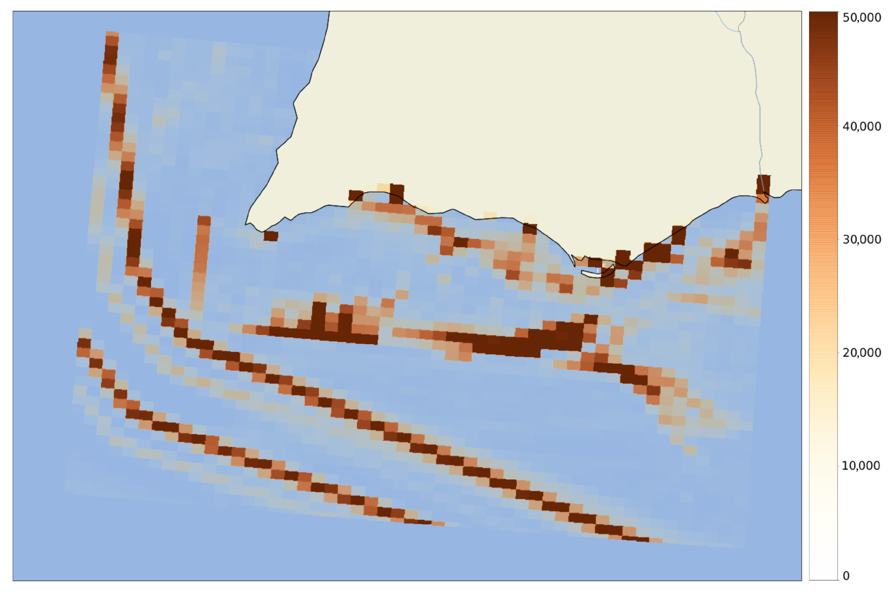
Figure 1, we can observe a 3D heatmap of the most common vessel positions in June 2018, on the Southern coast of Portugal. We can very clearly observe two main navigational corridors, with two slightly less frequent corridors next to these. There is also a very high frequency of AIS messages next to ports and on the Portuguese border with Spain, where the Guadiana river flows into the ocean.
The maritime control of national exclusive economic zones is performed by highly trained naval system operators, who permanently monitor the activity of vessels along the coast of the designated country through the use of command and control systems (C2), and whose data from navigating vessels is fed by the real-time stream of data received by coastal authorities.
The presented work has the satellite-based automatic identification system (AIS) as the fundamental basis, in order to infer the position and characteristics of vessels present in the maritime space. These messages, transmitted over very high frequency (VHF) audio waves, enable information such as the type of message, the vessel’s maritime mobile service identity (MMSI), timestamp, latitude and longitude of the vessel, speed, course, heading information, and type of manoeuvre, among other things, to be exchanged between vessels and the shore in real-time [
3]. The AIS system comes with important limitations. First, considering the system is reliant on the sensor information, measured in each vessel, this means that the received information will only be as accurate as the information measured by the per-vessel sensors. The reliance on the received AIS information for maritime control by officers on watch can also be seen as a downside. The possibility of tampering with sensors to send erroneous information, or to stop transmitting by turning off the AIS system, makes the duty of the officers in charge very difficult. The fact that not all ships are fitted with AIS means small vessels may not appear in the system. Unlike the long-range identification and tracking (LRIT), which uses closed-loop satellite communication [
4], the AIS works as a VHF broadcast system, limited to the range of the VHF waves. The broadcast nature of AIS also means this information is available to everyone in the vicinity and may lead to the transmission of erroneous information from another ship, which does not happen in LRIT communication.
Considering the high volume of data received, which may include over 1,500,000 messages every day, it is of little to no use without the appropriate set of tools that can help the operators extract information and knowledge regarding the maritime subspace in an automatic way.
The present problem of learning how to identify vessels performing abnormal trajectories and learn on the fly is especially complex considering that there seem to be no publicly available labelled datasets for this task. As such, we utilise an unlabelled dataset of past AIS message data for extracting meaningful information from the structured data of vessel motion paths. The focus of this study is to present an advance in the automatic identification of vessels deviating from their normal route of operation by extracting per-vessel information of the common trajectories. We present a system that can learn the unique navigational patterns for each vessel on the fly being able to identify and alert abnormal behaviours on the sea. This study was performed and validated on the southern and southwestern coast of Portugal.
This paper has been developed in collaboration with the EFFECTOR EU H2020 project (an end-to-end interoperability framework for maritime situational awareness at strategic and tactical operations) [
5], the primary goal of which is to improve the collaboration of European maritime authorities, with the application of an interoperability framework, along with data fusion and analytics functionalities for maritime situational awareness. The content of this paper is specifically targeting the development of maritime anomaly detection tools for the EFFECTOR framework.
3. Module Design
In this section, we provide details of the proposed work, which includes the two stages of the system, training and inference. The section is divided into six main parts. In
Section 3.1, we present the existing dataset for training and the data stream used for inference.
Section 3.2.1 describes the data preparation pipeline of the unlabelled raw AIS dataset.
Section 1 presents the method for computing the grid size per vessel and the generation of the appropriate binary search tree.
Section 3.2.3 demonstrates the final step of the training process, which is the calculation of the grid leap rates for each vessel. Finally, in
Section 3.3, we present the inference pipeline from the learned models and provide an overview of the online learning process.
3.1. Dataset and Data Stream
The data used for the task includes all received AIS messages for the region of the southwestern coast of Portugal, over a period of three years, from June 2017 to June 2020. Each line corresponds to a single AIS message, sent by a vessel at a given date and time. The following columns are present:
Message type: Integer between 1 and 27, which represents the type of message sent. The most common is message type 1, Scheduled Position Report, which accounts for approximately 82.4% of the data. Following this, messages of type 3, Special Position Report, response to interrogation, accounting for 10.4% of data. Messages of type 18, Standard Position Report for class B shipborne mobile equipment, account for 7.2% of data. The remaining messages as a whole account for under 0.1% of the data.
Repeat: Indicator if the message is repeated. Messages with a repeat equal to one should hold the same information as the first message sent.
MMSI: Unique vessel identifier.
Status: Vessel navigational status, depicted in
Figure 2a. The values range between 0 and 15, 15 being the default value “Undefined”, which represents the second-most common vessel status, accounting for 21.4% of the dataset. The most represented category is messages of type 0, Under Way Using Engine, around 56% of the dataset. Statuses 7 Engaged in Fishing and 5 Moored correspond to approximately 15.8% and 5.5% respectively. All other statuses correspond to the remaining 1.4% of data.
Turn: Denotes the number of degrees and the direction of turning of a vessel. It ranges between −128 and 127, corresponding negative values to counterclockwise turns and positive values to clockwise turns. The value −128 is a special value, used when no turning information is available from the vessel, which in our case corresponds to 54.38% of data. Around 32.64% of vessels reported a rate of turn of 0º, 1.15% with rates of turn less than or equal to 3º to the left or the right ([−3,3]). 4.77% and 4.46% of vessels reported rates of turn between 3º and 63º to the left and right respectively. Finally, 1.33% and 1.24% of vessels reported rates of turn of exactly 127 degrees left and right. A summary of this data can be observed in
Figure 2b.
Speed: Speed over ground (SOG) of the vessel. A total of 99.9% of the registered data is between 0 and 25 knots, the distribution of which we can see in
Figure 2c. Approximately 63% of the remaining 0.1% of data is at exactly 102.3 knots, which leads us to believe this to be an error code.
Accuracy: Defines the position precision, low (default) when the sensor’s precision is over 10 m, accounting for 34% of the data and high (66% of data) when the precision is less than or equal to 10 m.
Longitude: Reported vessel longitude.
Latitude: Reported vessel latitude.
Course: Course over ground (COG), which represents the degrees of navigation in relation to the geographic north (true north),
Figure 2d. The value 511 is used as Not Available. In
Figure 2d, we can observe the course distribution in the dataset. The sum of the reported courses equal to 0º corresponds to 4.65% of the dataset. We can also observe very high representation in the dataset around the angles of 110°, 280°, and 340°, with smaller peaks in the angles 130, 310, and 270. The values 360 and above are various error codes, with 360 considered “Undefined” by European standards. All values over 359 are assumed to be errors.
Heading: Represents the degrees of navigation in relation to the magnetic North, as seen in
Figure 2f. The value 511 is used as (Not Available). In
Figure 2e we can observe that 57.5% of the messages do not include Heading information.
Second: Information about the second in the minute on which the message was broadcast. This value is an integer between 0 and 63, where the values 60 to 63 represent (Unavailable) timestamps and other error codes. Code 60 corresponds to under 0.5% of the original dataset, whereas the remaining error codes represent under 0.002% of the total.
Manoeuvre: Identifies if the vessel is performing any type of manoeuvre on the sea. It takes the values 0 for Unavailable, 1 for Not engaged in special manoeuvre and 2 for Engaged in special manoeuvre. In this particular dataset, around 99.7% of the data is labelled with value 0, Unavailable.
Timestamp: Indicates the time of broadcast of the message.
Ship type: Ranges between 0 and 99, being the most represented categories (Sailing), followed by Pleasure Craft. Approximately 3.5% of messages have ship type 0, Unavailable.
3.2. Training Pipeline
In this section, we provide an overview of the model training pipeline, depicted in
Figure 3. The system receives raw AIS data, corresponding to the area of interest on the sea and runs a linear training process consisting of data preparation, detailed in
Section 3.2.1, slicing the space into grids adapted to the vessel in question and discrediting the vessel location according to its grid, detailed in
Section 1. Finally, the leap rate matrices are calculated per vessel (
Section 3.2.3).
3.2.1. Data Preparation
This Section deals with the data preparation pipeline, as shown in
Figure 4, part of the high-level training pipeline explained in
Section 3.2.
As observed in the data analysis, all messages with repeat fields that are not equal to zero have been sent more than once, oftentimes reaching the coast in repeat. For this reason, we first removed all repeated messages, for which the field repeat is not equal to zero and which are preceding a message with the same content less than 10 s prior to the reception of the said repeated message.
An important concept to infer is the definition of a trip. We define a trip as a sequence of chronologically ordered points bound to space and time for the same vessel, represented by received AIS messages, and with a time window between two consecutive points no larger than two hours. Based on this definition, we first group the dataset according to the existing MMSIs and order each group by the received date. Each vessel dataset is now comprised of all messages received for a specific vessel, ordered chronologically. We then iterate the dataset and, if two consecutive messages have been received with an interval of over two hours, we split the dataset into two. This routine is done recursively until we end up with an array of trips for each vessel. The cleaned data has the format of an array of vessels with size J
, where each vessel
includes an array of trips of size K
. Each trip is a group of AIS messages of size L, where each message includes the parameters explained in
Section 3.1,
.
By analysing the size of each trip vector in
Figure 5, we conclude that many of the found trips have less than 50 AIS messages. In
Figure 6, we can analyse the location of these small trips, grouped by vessel type, which indicates most of these correspond to small trips inside ports, rivers, and vessels that immediately left the area of surveillance. All of these trips were discarded from the training dataset.
3.2.2. Creation of the Grid and Binary Search Tree
The present work’s algorithm proposal is based on a leap rate grid, where the leaping rate between two adjacent grid rectangles is learned for each vessel. In the present work, we consider a leap to be defined as a transition from a specific grid rectangle to any of its adjacent grid rectangles. The grid must be small enough to account for small vessels that perform near-shore fishing and wide enough for large vessels that perform intercontinental journeys. The inherently different characteristics of vessels, even when analysing vessels from the same category, presents themselves as challenges for inferring the appropriate width and height of the grid. In
Figure 7, we can observe an example of a very wide grid, juxtaposed with the map of the southern coast of Portugal.
In order to adjust the grid rectangle width and length hyperparameters for each vessel, we propose a simple approach based on the average vessel speed. Considering the array of vessels V, where each element
has an array of trips
, where
represents the trip j of the vessel
, the average speed is defined as the sum of all recorded speeds for every received AIS message k, for every trip
over the total number of elements across all trips in the array
. For each vessel, we iterate its trip vector and calculate the average speed of all registered speed values that are over 1 knot. Formally, the sum of all speed values for vessel
is defined as
This value is then divided by the sum of all lengths of the trip vectors without messages with speeds lower than 1 knot. In our experimentation, we found out a good value of the grid would be approximately five times the average speed of the vessel.
One of the major issues with grid-based approaches presented in
Section 2 is the speed of discretization of the dataset and testing inference, as we must find the location of the vessel in the grid layout. Iterating a vector of grid rectangles and verifying the inclusion of the vessel in the rectangle element is time-consuming and very costly. We propose a solution to this problem based on a binary-search tree for mapping the ocean grid, as seen in
Figure 8. The root node corresponds to the entire area in analysis, which is recursively split into two longitudinal sections of equal width and height until the height of the rectangles are, at most, the calculated value of five times the average vessel speed. The tree then begins splitting the rectangle slices latitudinally into two rectangles of equal dimensions and areas, until the requirement of the rectangle width is met. This approach does not ensure all grid elements are squares but it significantly speeds up the search process. The creation of the binary search tree this way ensures that the tree is balanced, as both rectangles in the same tree depth are of the same size. For this reason, the complexity of the algorithm for the discretization of the dataset, using binary search is
, as in each comparison, half of the tree is eliminated.
All vessel trip vectors are then discretized by using the computed binary search tree. For each AIS message present in the trip data, we apply the binary search function, as shown in Algorithm 1. Depicted in
Figure 9 is an example of a discretized vessel trip, using the learned grid for the vessel. A faint line is shown, corresponding to the original trip performed by the vessel. Overlayed are the grid squares that have been traversed on this trip.
| Algorithm 1: Binary Search |
| |
| functionFindLocation(, ) |
| if is Null then |
| return ▹ End condition |
| else if in then |
| return |
| end if |
| return |
| end function |
3.2.3. Calculation of Leap Rate Matrices
The discretized dataset is the basis for the calculation of the matrices that model the leap rates between adjacent nodes for different vessels. A leap is defined as an oriented vector , where corresponds to the ID of the rectangle position of the vessel at time t, and corresponds to the ID of the rectangle to which the vessel has navigated. The model explained in the present section learns the rate of a leap associated with each of these oriented vectors, for each vessel. In an instance where the vessel has never performed a navigation between two nodes, the rate will be equal to zero.
Bayesian conditional probabilities are often used as the basis for the calculation of grid-based probabilities on the maritime subspace, as seen in the work by Mascaro et al. [
24] and Zhen et al. [
25], which is the basis for the suggested approach.
The vectors are generated by iterating the discretized trip list. For each element in a trip, a vector with a tail corresponding to the message grid node ID, and a tip corresponding to the following message’s grid node ID is generated. If the tail and tip are the same node, meaning no navigation between nodes has been observed, no vector is generated. For each vessel
, being
the k-th AIS message present in a certain trip j of vessel
:
The generated vectors are now grouped by the grid node ID, tail of the vectors, counting the total number of leaps from each grid node ID and the frequency of each unique vector. The leap rate for a certain vector
is the frequency of the navigation
in the data, divided by the total number of leaps from node
a. Both the frequency and the total number of leaps are stored for online learning, explained in
Section 3.3.
With the computed values, we calculate the count of navigations for each node. We generate a three-by-three matrix for each grid node, where the centre of the matrix, representing the navigations between the grid node and itself, is equal to the total number of navigations performed by the vessel from the node to any adjacent node. Each of the other elements represents the total number of navigations with the adjacent nodes.
The result of this calculation, important for inference, is a data cube of registered leaps, as depicted in
Figure 10, where for each vessel
v, a different grid layout is associated with it, mapping latitude
and longitude
coordinates to grid node IDs, with associated matrices of navigations.
3.3. Inference and Online Learning
The present section explains the inference and online learning capabilities of the module, depicted in
Figure 11. As new AIS messages arrive in the system, they are preprocessed, in order to extract the necessary information for the inference model.
For inference, the following information is required to be stored:
The binary tree structure for each vessel, which includes node IDs and leap count matrices. These matrices include the count of navigations registered between the node and each adjacent node, and the total number of navigations registered from each node, stored in the central value of the matrix.
The current location of the vessel on the grid.
For every received AIS message from the data stream, we utilize the vessel-specific binary search to infer its grid position. We then compare the current position of the vessel with its previously registered position. Two scenarios can happen.
The previously registered position of the vessel is the same as its current position. If this is the case, no leap has been registered, the vessel is not in an anomalous trajectory, and nothing is changed.
The previously registered position is different to its current position. In this case, we must infer the rate associated with the leap between the two nodes and update the vessel information.
The leap rate values are calculated by dividing the leap count matrix by the total number of navigations registered for the node, which results in the matrix represented in
Figure 12. The centre of the matrix, representing vessels that have made a move from one point and another, both inside the same grid node, is always equal to 1.
If the calculated leap rate between the previously registered position and the current position is below a certain threshold, we define it to be an abnormal trajectory. In our tests, by observing the found matrices for different vessels and deciding what would make sense to be considered an anomalous trajectory, we have found the value of 0.125 to work well for this problem.
Finally, for online learning, we must update the trajectory information, by increasing the count of the specific registered leap for the vessel and the total number of registered navigations for the node. The current node location of the vessel is also updated.
The inference operation includes several sequential statements. First, a simple query fetches the appropriate binary search tree based on a hashed ID, with the complexity of , followed by a binary search for the current position of the vessel, with a complexity. The online learning updates the leaf node information in the BST and updates the registry in the database, which has a complexity. For this reason, the total complexity of the inference and online learning capabilities is .
4. Simulation Tests
We have performed tests by using clustering algorithms, namely DBSCAN and OPTICS. From the conducted tests, these approaches did not produce satisfactory results. This is due to the lack of spatial homogeneity in AIS data, wherein vessels with different speeds report points of varying distances according to their current speed. The comparison between coastal vessels versus open sea navigation shows that coastal trips are mostly dominated by smaller vessels, with a very dense cluster of points and of varying speeds, whereas open sea trips are much more sparsely represented, with points further from each other. Some temporal variability is also observed, showing problematic results when the AIS signal fails on the high seas. For these reasons, the found clusters were not cohesive and did not represent the trips well, as it becomes challenging to find a parameter epsilon that adjusts to a data distribution with varying densities.
To tackle the spatial diversity in the data, tests were made with interpolation functions, to ensure no consecutive points on the same trip are spatially separated by more than a certain defined threshold. Despite mitigating the problem with open sea trip point density, vessels with multiple trips departing from the same location still showed a much higher concentration of points around ports, which still posed a challenge for applying a density cluster algorithm. The application of interpolation techniques did not seem to solve the problem with the cluster misrepresentation of trips, increasing the algorithm complexity and scaling the dataset points.
The proposed solution has been tested and validated on the Portuguese maritime trial, conducted on the 21st of April 2022, on the southern coast of Portugal, with assistance from the EFFECTOR consortium partners, namely Engineering Ingegneria Informatica and the Portuguese navy, which provided the military vessel SAGITARIO for validation of the present system. The trial consisted of an entire day of vessel monitoring activities in the southern and southwestern coast of Portugal, to evaluate the goodness of fit of the proposed solution and its response in a large-scale real-time situation. First, the Portuguese vessel SAGITARIO left the Portimão harbour and started to drift northeast, approaching the shoreline. The vessel then started accelerating south, out of their normal course of action, until a deviation from route anomaly was triggered. All other vessel activity was monitored on the fly, to identify vessels out of its normal course. Approximately 1600 messages were received and processed every minute by the system, and anomalies were raised in real time for the operators to analyse.
5. Discussion and Conclusions
This research work focused on providing a study for the problem of route prediction, exploring machine learning techniques to automatically extract route patterns from historical AIS data, from which main routes are obtained to provide guidelines for future movement. The research involvement of academia/research, industry, authorities and society organizations allowed leverage to develop technologies, frameworks and innovative solutions for improving the sustainability of the sea. The present work presents a solution proposition for the scalability limitation of grid-based methods, described by Pallotta et al. [
22]. The authors state that grid-based methods, such as [
12,
13,
14,
15,
16,
17], are only effective on small-scale surveillance, requiring heavy computation as the area of surveillance increases, due to the complex discretization operation and the difficulty of selecting an appropriate grid cell value. The proposed dynamic grid size, along with the binary search tree algorithm for vessel trip discretization allows for grid-based algorithms to be utilized on a larger scale for maritime abnormal trajectory detection. The ability of the system to learn over time, as new data is added to the system also poses an advantage over other proposed systems in the literature. The ability of the system to automatically generate alerts on the fly that can warn the system operators and maritime authorities about potentially suspicious or abnormal events occurring in the maritime space contributes toward a better knowledge of the maritime domain and for more informed decisions to be taken by operators.
This method comes with some limitations, as new and never-before-seen vessels on the coast will not have an associated leap rate model. In order to solve this problem, the model of a vessel with similar characteristics or routes, or an ensemble of models from similar vessels may be used in this case. The efficiency of such methods is yet to be tested. The inherently convoluted definition as to which poses to be a deviation from a normal route makes the proposed methods difficult to compare and evaluate their performance as the data is unlabelled, some deviations from route may be justifiable, and several vessels, mainly tourism-related and leisure boats, may have unpredictable routes.


