
Spatial Kinematic Analysis of a Tracked Forest Fire Engine with Fish-Bellied Swing Arm Torsion Bar Suspension
Abstract
:1. Introduction
2. Structural Design of a Tracked Fire Engine with Fish-Bellied Swing Arm Torsion Bar Suspension
3. Structural Analysis of Fish-Bellied Swing Arm Torsion Bar Suspension
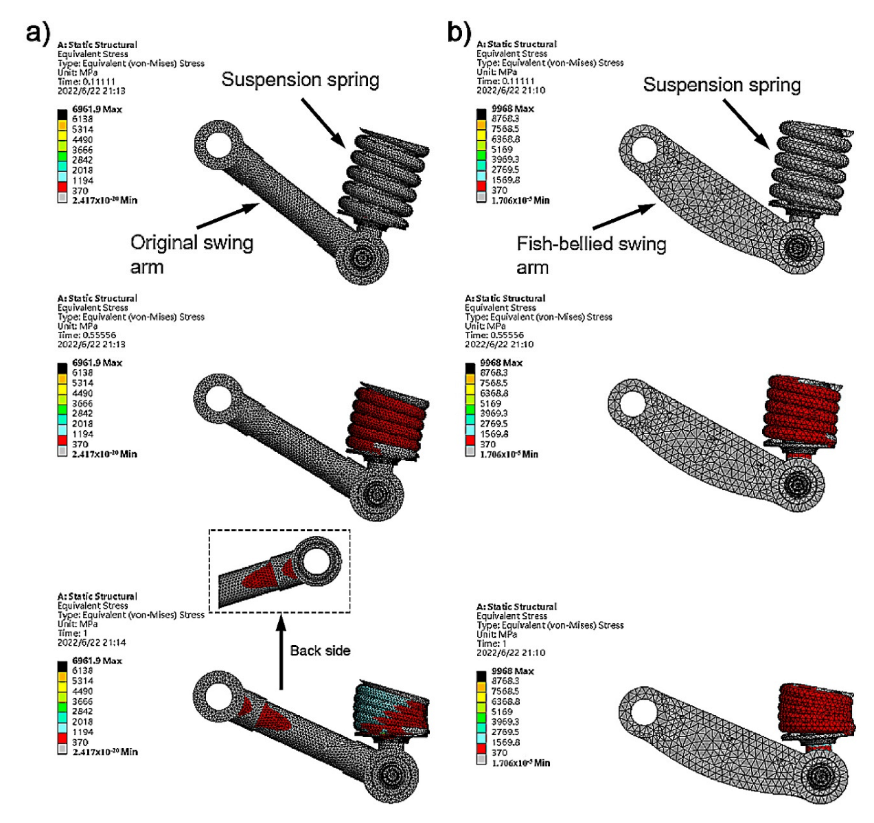
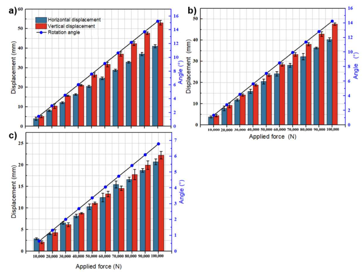
3.1. Stress Analysis of Fish-Bellied Swing Arm
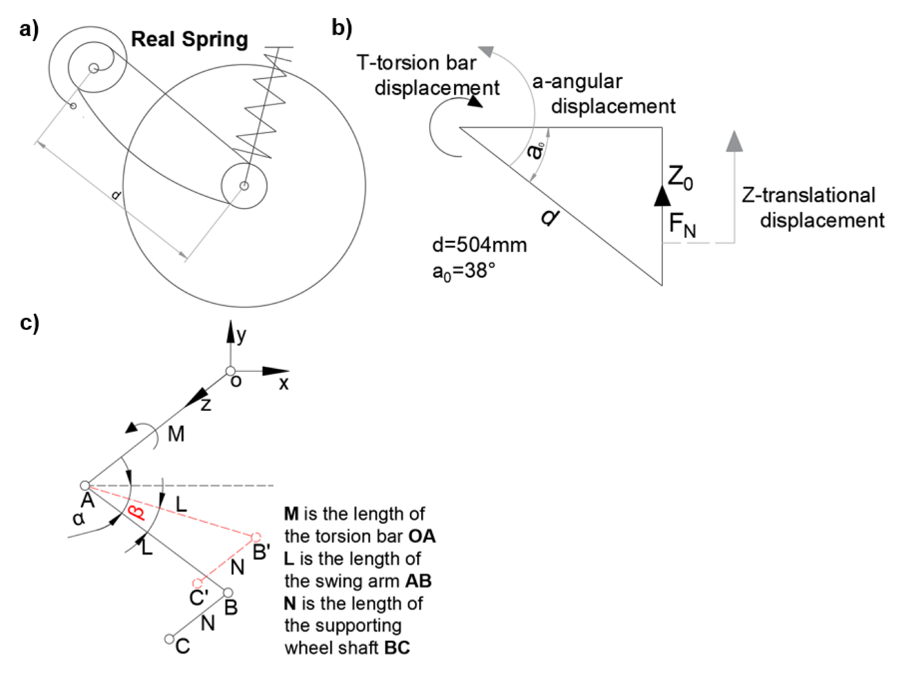
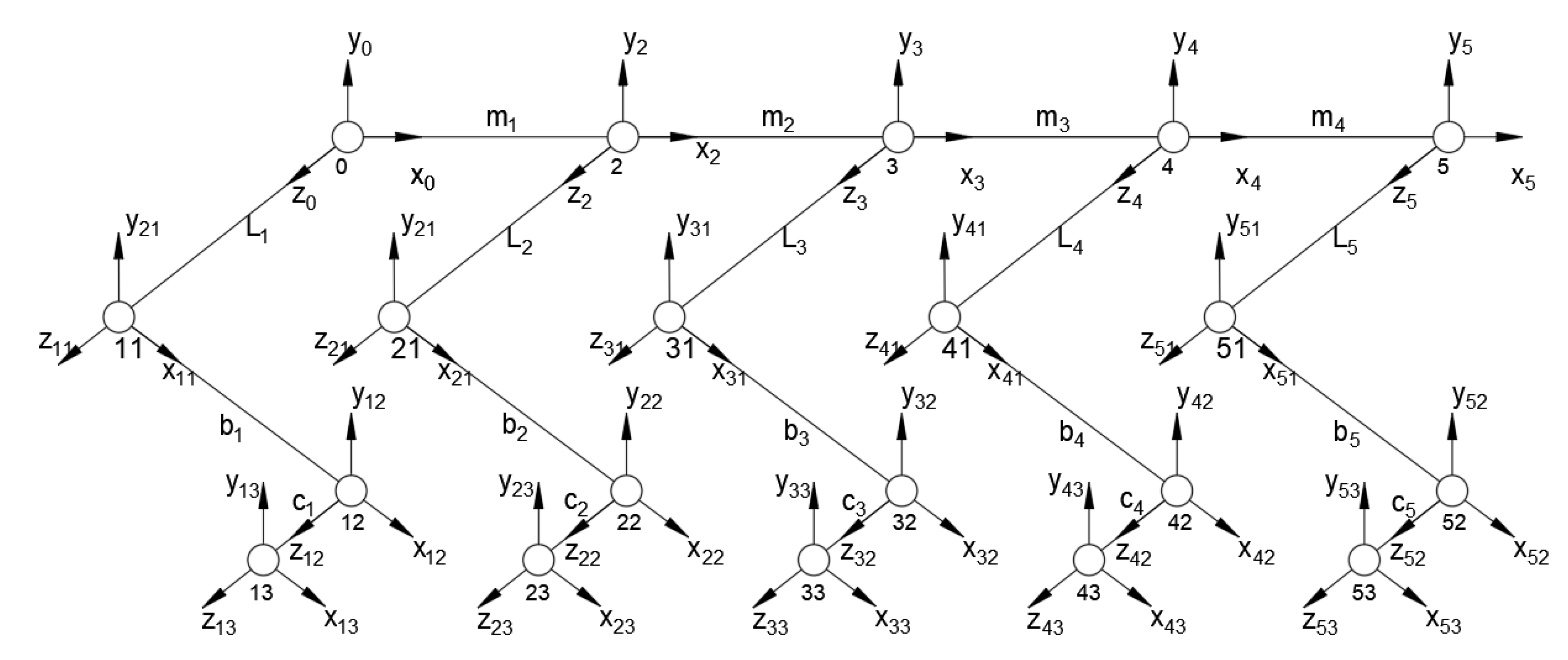
3.2. Kinematic Analysis of Fish-Bellied Swing Arm Torsion Bar
4. Simulation Analysis of Fish-Bellied Swing Arm Torsion Bar Suspension
4.1. Static Simulation Analysis of Swing Arm Suspension
4.2. Kinematic Simulation Analysis of Swing Arm Suspension
- (a)
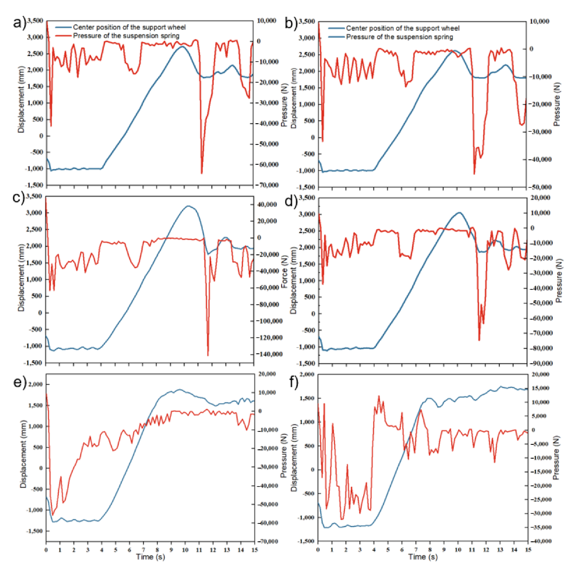
- At the beginning of the simulation, the tracked vehicle falls to the ground from a height of 280 mm and moves at a uniform speed in the horizontal direction. The position of the centroid of the supporting wheel remains unchanged, except for the falling height in the range of 0–4 s; when the tracked vehicle falls, the suspension spring is subjected to a certain squeezing pressure under the action of gravity, and when the tracked vehicle moves horizontally, the suspension spring swings up and down in a specific range. Compared with (a–d) of Figure 8, it can be seen that the extrusion pressure of the suspension spring after the improved chassis is smaller than before the improvement. The position of the centroid of the supporting wheel is the same as the up and down swing of the suspension spring when driving horizontally.
- (b)
- At 4–9 s, the tracked vehicle drives along the slope, the centroid position of the supporting wheel continues to rise, and the suspension spring tends to stabilize after being squeezed on the slope.
- (c)
- At 9–11 s, the suspended tracked body falls to the ground in a parabola under the action of gravity and driving force, the centroid position of the supporting wheel rapidly drops, and the pressure of the suspension spring quickly increases when it touches the ground. Compared with Figure 9a,b in Figure 9, it can be observed that when the tracked vehicle body hits the ground before the suspension improvement, the centroid position of the supporting wheel is lower, and the suspension spring is subjected to more significant pressure; the pressure on the improved suspension spring is decreased by 29.6%, and the centroid position is increased by 46.61 mm.
- (d)
- At 11–15 s, the tracked vehicle begins to cross the obstacle, and the centroid position of the supporting wheel first rises and then decreases; the suspension spring pressure drops, and after the front supporting wheel hits the ground crossing the obstacle, the suspension spring pressure rapidly increases, thus completing the simulation process of 15 s.
5. Experimental Verification of Fish-Bellied Swing Arm Torsion Bar Suspension
5.1. Test Device
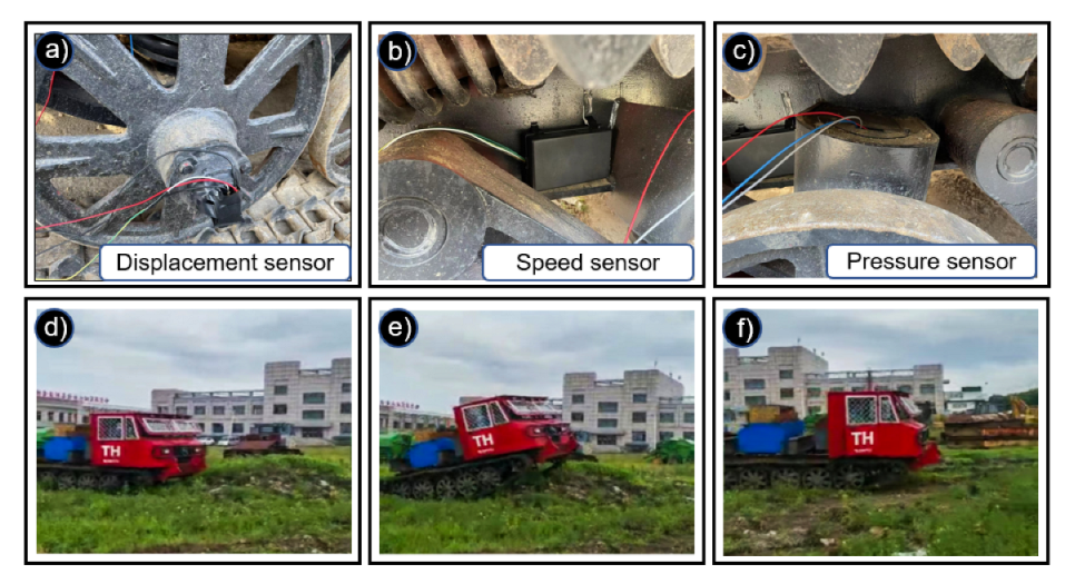
5.2. Test Plan
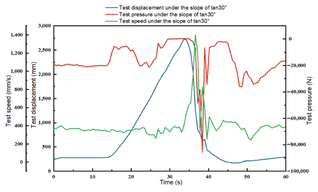
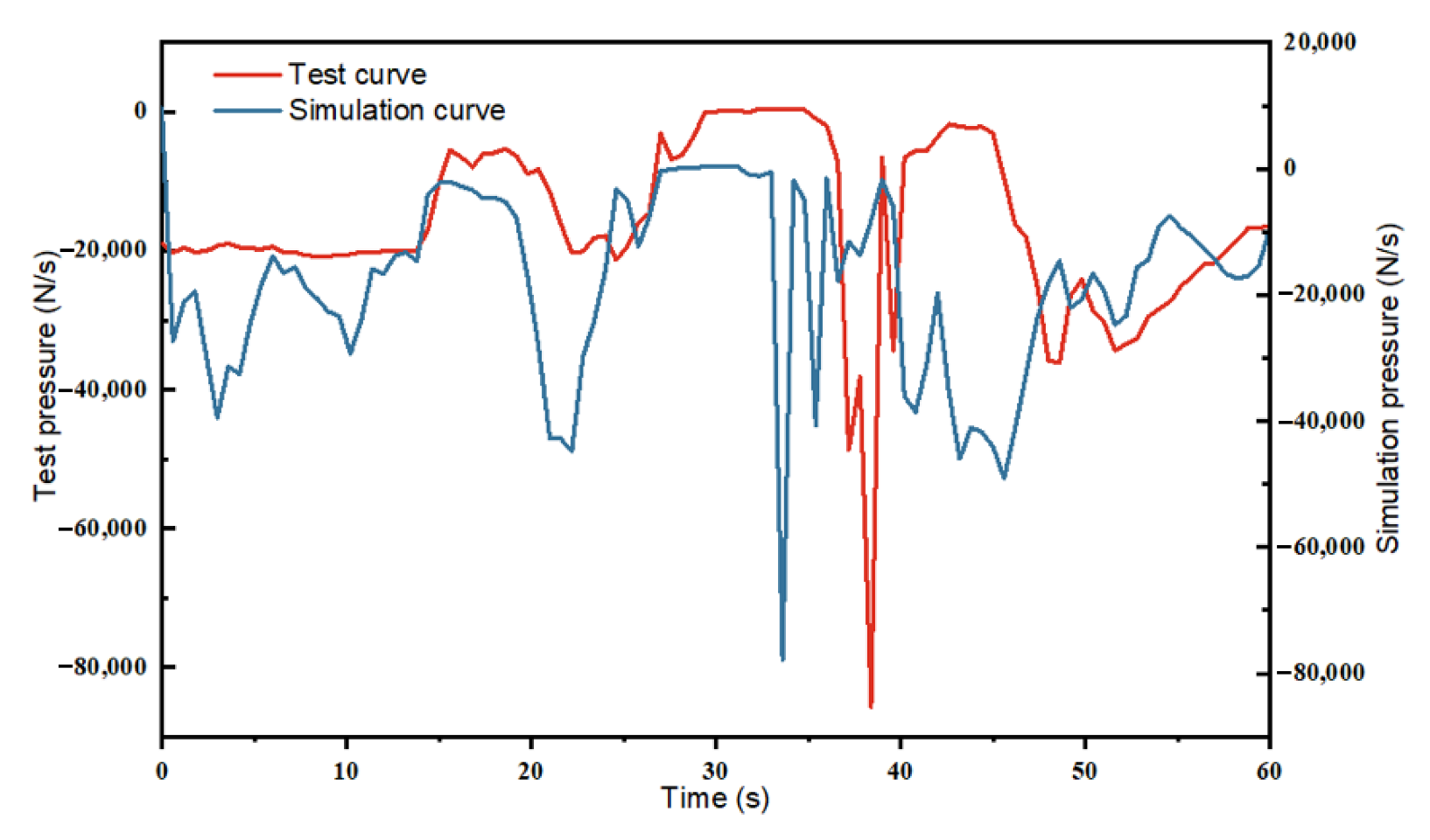
5.3. Test Result
6. Conclusions
- (1)
- Based on D-H coordinate change theory, the kinematics mathematical model of fish-bellied swing arm torsion bar suspension in a forest with an unstructured terrain environment was established. The kinematics equation of the arm swing torsion bar of a tracked fire engine was derived. Furthermore, the position and pose information of a tracked fire engine’s arm swing torsion bar were obtained. The theoretical basis for the kinematic characteristics analysis of the fish-bellied swing arm torsion bar suspension was provided;
- (2)
- The static and dynamic simulation model of fish-bellied swing arm suspension was established, and the climbing obstacle and falling impact conditions in the unstructured forest environment were simulated. The force cloud diagram and displacement simulation curve of the fish-bellied swing arm were obtained, which provided the basis for the theoretical verification of the kinematics characteristics of the fish-bellied swing arm torsion bar suspension;
- (3)
- The principle prototype of fish-bellied swing arm torsion bar suspension was developed and carried out in the actual vehicle test. The test results verified the accuracy of theoretical calculation and the effectiveness of simulation analysis, which provides technical support for the actual development of forest-tracked fire trucks.
Supplementary Materials
Author Contributions
Funding
Institutional Review Board Statement
Informed Consent Statement
Data Availability Statement
Conflicts of Interest
References
- Romário, O.; De, S.; Rafael, C.D. Alexandre Schiavetti Modeling susceptibility to forest fires in the central corridor of the atlantic forest using the frequency ratio method. J. Environ. Manag. 2021, 296, 113343. [Google Scholar]
- Guangdong, T.; Amir, M.; Fathollahi, F.; Yaping, R.; Zhiwu, L.; Jiangyu, J. Multi-objective Scheduling of Priority-based Rescue Vehicles to Extinguish Forest Fires using a Multi-objective Discrete Gravitational Search Algorithm. Inf. Sci. 2022, 608, 578–596. [Google Scholar]
- Jorge, J.; João, R.P.; Jérôme, M.; Daniela, A.; Luís, M.R.; Carlos, V. Automatic forest fire danger rating calibration: Exploring clustering techniques for regionally customizable fire danger classification. Expert Syst. Appl. 2022, 193, 116380. [Google Scholar]
- Fengju, B.; Mohammad, S.G. Intelligent and vision-based fire detection systems: A survey. Image Vis. Comput. 2019, 91, 103803. [Google Scholar]
- Moinuddin, K.A.M.; Sutherland, D. Modelling of tree fires and fires transitioning from the forest floor to the canopy with a physics-based model. Math. Comput. Simul. 2020, 175, 81–95. [Google Scholar] [CrossRef]
- Marian, R. Determination the ability of military vehicles to override vegetation. J. Terramechanics 2020, 91, 129–138. [Google Scholar]
- Guang, H.; Mingxian, X.; Qingkai, K.; Lihai, W. Design and analysis of triangle crawler wheeled forest fire truck. Fire Sci. Technol. 2019, 38, 983–987. [Google Scholar]
- Wong, J.Y.; Huang, W. Approaches to improving the mobility of military tracked vehicles on soft terrain. Int. J. Heavy Veh. Syst. 2008, 15, 127–151. [Google Scholar] [CrossRef]
- Wong, J.Y.; Huang, W. Evaluation of the effects of design features on tracked vehicle mobility using an advanced computer simulation model. Int. J. Heavy Veh. Syst. 2005, 12, 344–365. [Google Scholar] [CrossRef]
- Sun, S.; Wu, J.; Ren, C.; Tang, H.; Chen, J.; Ma, W.; Chu, J. Chassis trafficability simulation and experiment of a LY1352JP forest tracked vehicle. J. For. Res. 2021, 32, 1315–1325. [Google Scholar] [CrossRef]
- Yang, C.; Cai, L.; Liu, Z.; Tian, Y.; Zhang, C. A calculation method of track shoe thrust on soft ground for splayed grouser. J. Terramechanics 2016, 65, 38–48. [Google Scholar] [CrossRef]
- Wang, P.X.; Rui, X.T.; Yu, H.L. Study on dynamic track tension control for high-speed tracked vehicles. Mech. Syst. Signal Process. 2019, 132, 277–292. [Google Scholar] [CrossRef]
- Zuo, P.; Cheng, K.; Zhou, Y.Z. Study on torsion bar spring of all-terrain articulated tracked transport vehicle. J. Mach. Des. 2018, 8, 12–16. [Google Scholar]
- Navarro, K.M.; Clark, K.A.; Hardt, D.J.; Reid, C.E.; Lahm, P.W.; Domitrovich, J.W.; Butler, C.R.; Balmes, J.R. Wildland firefighter exposure to smoke and COVID-19: A new risk on the fire line. Sci. Total Environ. 2021, 760, 144296. [Google Scholar] [CrossRef] [PubMed]
- Yamakawa, J.; Watanabe, K. A spatial motion analysis model of tracked vehicles with torsion bar type suspension. J. Terramechanics 2004, 41, 113–126. [Google Scholar] [CrossRef]
- Tomasz, N.; Andrzej, J.; Janusz, K. Modeling verification of an advanced torsional spring for tracked vehicle suspension in 2S1 vehicle model. Eng. Struct. 2021, 229, 111623. [Google Scholar]
- Xue, Z.P.; Li, M.; Jia, H.G. Modal method for dynamics analysis of cantilever type structures at large rotational deformations. Int. J. Mech. Sci. 2015, 93, 22–31. [Google Scholar] [CrossRef]
- Li, Y.; Liu, S.M.; Qu, D.D.; Shi, M.M. Dynamics and statics Analysis of Coal Mine Inspection Robot manipulator. Mech. Transm. 2017, 41, 85–89. [Google Scholar]
- Zhang, C.; Zhang, L.Y. Kinematics analysis and workspace investigation of a novel 2-DOF parallel manipulator applied in vehicle driving simulator. Robot. Comput. -Integr. Manuf. 2013, 29, 113–120. [Google Scholar] [CrossRef]
- Xiaobin, H. Experimental analysis on completion of over-aged fish-bellied steel truss bridge after overhaul. Highway 2021, 66, 122–126. [Google Scholar]
- Zhuang, S.C.; Zhang, J.L.; Zhang, C.H.; Li, S.L. Study on stiffness of prestressed fish-web steel bracing system. J. Civ. Eng. 2021, 54, 18–25. [Google Scholar]
- Yu, X.; Liu, C.; Qin, W.M.; Xiang, K. Stress mechanism and finite element analysis of prestressed fish-bellied beam system. J. Anhui Archit. Univ. 2017, 25, 1–5. [Google Scholar]
- Jingbin, S.; Chong, M.; Yazhou, Z.; Guoping, C.; Yanjie, Z.; Fuzeng, Y.; Zhijie, L. Design and physical model experiment of an attitude adjustment device for a crawler tractor in hilly and mountainous regions. Inf. Process. Agric. 2020, 7, 466–478. [Google Scholar]
- Lv, K.; Mu, X.; Li, L.; Xue, W.; Wang, Z.; Xu, L. Design and test methods of rubber-track conversion system. Proc. Inst. Mech. Eng. Part D J. Automob. Eng. 2018, 233, 1903–1929. [Google Scholar] [CrossRef]
- Arkadiusz, M.; Tomasz, C.; Wojciech, K.; Gabriel, M. Numerical simulation of active track tensioning system for autonomous hybrid vehicle. Mech. Syst. Signal Process. 2017, 89, 108–118. [Google Scholar]
- Yu, X.Y.; Gao, H.B.; Deng, Z.Q. Different kinematics modeling method and analyzing of new lunar rover with eight wheels. J. Beijing Univ. Aeronaut. Astronaut. 2009, 35, 457–463. [Google Scholar]
- Cai, Z.S.; Hong, B.R.; Wei, Z.H. Kinematics, dynamic analysis and simulation of lunar rover. J. Huazhong Univ. Sci. Technol. (Nat. Sci. Ed.) 2004, 32, 35–37. [Google Scholar]
- Yun, L.; Yong, J. Kinematics analysis and experimental research of deep sea mining robot. UPB Sci. Bull. 2021, 83, 2–18. [Google Scholar]
- Dziubak, T.; Boruta, G. Experimental and Theoretical Research on Pressure Drop Changes in a Two-Stage Air Filter Used in Tracked Vehicle Engine. Separations 2021, 8, 71. [Google Scholar] [CrossRef]
- Dziubak, T.; Karczewski, M. Experimental Study of the Effect of Air Filter Pressure Drop on Internal Combustion Engine Performance. Energies 2022, 15, 3285. [Google Scholar] [CrossRef]
- Abdullah, N.R.; Shahruddin, N.S.; Mamat, A.M.I.; Kasolang, S.; Zulkifli, A.; Mamat, R. Effects of Air Intake Pressure to the Fuel Economy and Exhaust Emissions on a Small SI Engine. Procedia Eng. 2013, 68, 278–284. [Google Scholar] [CrossRef] [Green Version]


| Name | Material | Diameter (m) | Lengh (m) | Young’s Modulus (Pa) | Poisson’s Ratio | Shear Modulus (Pa) | Anti- Torsional Stiffness (N/m2) |
|---|---|---|---|---|---|---|---|
| Elastic torsion bar | 60Si2Mn | 0.072 | 1.515 | 2.06 × 10¹¹ | 0.29 | 7.98 × 10¹⁰ | 42,000 |
| Joint i | ai−1 | αi−1 | di | θi |
|---|---|---|---|---|
| 11 | 0 | 0° | L1 | θ11 (38°) |
| 12 | b1 | 0° | 0 | θ12 (0°) |
| 13 | 0 | 0° | c1 | θ13 (360°) |
| 2 | m1 | 0° | 0 | θ2 (38°) |
| 21 | 0 | 0° | L2 | θ21 (0°) |
| 22 | b2 | 0° | 0 | θ22 (0°) |
| 23 | 0 | 0° | c2 | θ23 (360°) |
| 3 | m2 | 0° | 0 | θ3 (0°) |
| 31 | 0 | 0° | L3 | θ31 (38°) |
| 32 | b3 | 0° | 0 | θ32 (0°) |
| 33 | 0 | 0° | c3 | θ33 (360°) |
| 4 | m3 | 0° | 0 | θ4 (0°) |
| 41 | 0 | 0° | L4 | θ41 (38°) |
| 42 | b4 | 0° | 0 | θ42 (0°) |
| 43 | 0 | 0° | c4 | θ43 (360°) |
| 5 | m4 | 0° | 0 | θ5 (0°) |
| 51 | 0 | 0° | L5 | θ51 (38°) |
| 52 | b5 | 0° | 0 | θ52 (0°) |
| 53 | 0 | 0° | c5 | θ53 (360°) |
| Tan24° | Tan26° | Tan28° | Tan30° | Tan32° | Tan34° | Tan36° | Tan38° | Tan40° | Tan42° | Tan44° | |
|---|---|---|---|---|---|---|---|---|---|---|---|
| Test | P | P | P | P | P | P | P | P | F | F | F |
| Simulation | P | P | P | P | P | P | P | P | P | P | F |
Publisher’s Note: MDPI stays neutral with regard to jurisdictional claims in published maps and institutional affiliations. |
© 2022 by the authors. Licensee MDPI, Basel, Switzerland. This article is an open access article distributed under the terms and conditions of the Creative Commons Attribution (CC BY) license (https://creativecommons.org/licenses/by/4.0/).
Share and Cite
Zhou, Y.; Ding, Z.; Ding, D.; Xu, Y.; Yang, X.; Li, Z.; Cai, Y.; Sun, S. Spatial Kinematic Analysis of a Tracked Forest Fire Engine with Fish-Bellied Swing Arm Torsion Bar Suspension. Appl. Sci. 2022, 12, 11198. https://doi.org/10.3390/app122111198
Zhou Y, Ding Z, Ding D, Xu Y, Yang X, Li Z, Cai Y, Sun S. Spatial Kinematic Analysis of a Tracked Forest Fire Engine with Fish-Bellied Swing Arm Torsion Bar Suspension. Applied Sciences. 2022; 12(21):11198. https://doi.org/10.3390/app122111198
Chicago/Turabian StyleZhou, Yuan, Zian Ding, Dong Ding, Yue Xu, Xinchen Yang, Zongxu Li, Yuwei Cai, and Shufa Sun. 2022. "Spatial Kinematic Analysis of a Tracked Forest Fire Engine with Fish-Bellied Swing Arm Torsion Bar Suspension" Applied Sciences 12, no. 21: 11198. https://doi.org/10.3390/app122111198