Article

Femtosecond-Level Frequency Transfer at 10 GHz over Long Fiber Link with Optical–Electronic Joint Compensation

1
Mathematics and Information Science, Guangzhou University, Guangzhou 510006, China
2
College of Science, Kaili University, Kaili 556099, China
3
Science and Technology on Communication Security Laboratory, Institute of Southwestern Communication, Chengdu 610041, China
4
School of Automation Engineering, University of Electronic Science and Technology of China, Chengdu 611731, China
*
Author to whom correspondence should be addressed.
Appl. Sci. 2022, 12(21), 11262; https://doi.org/10.3390/app122111262
Submission received: 27 September 2022 / Revised: 31 October 2022 / Accepted: 2 November 2022 / Published: 7 November 2022
(This article belongs to the Special Issue New Chances of Optical Fiber Network)

Abstract

:
We report a fiber-optic 10 GHz frequency transfer technique based on an optical–electronic joint phase compensator. A highly stable frequency signal at 10 GHz was transferred in a 50-km long fiber link by using this technique. Two key parameters of the frequency dissemination, the timing fluctuation and frequency stability were both measured. The experimental results show the root-mean-square timing fluctuation of the transferred microwave is about 103 fs within 10,000 s, and the frequency stability for the transmission link is 2.2 × 10⁻¹⁴ at 1 s and 8.5 × 10⁻¹⁷ at 2000 s. The technique proposed in this paper provides a powerful tool which can be used to transfer atomic clocks (e.g., commercial H-master and Cs clocks) in a long fiber link.

1. Introduction

The transfer of extremely high frequency signals plays a very important role in the fields of precision science and engineering, for instance, astronomical observation, frequency standard, optical-microwave synthesis, and navigation [1,2,3,4]. The main goal of frequency transfer is to distribute the frequency signal from one point to another without degrading the stability of the frequency signal during this process [5]. Due to the low attenuation and high reliability of optical fiber, the technique of time and frequency transfer over optical fiber link has achieved a rapid development. In recent years, there have been many reports of fiber-optic frequency transfers. The transmission distance ranges from hundreds of meters to hundreds of kilometers, and the root-mean-square (RMS) timing fluctuation have reached the level of picosecond or sub-picosecond [6,7,8,9,10,11,12,13,14,15,16,17,18,19,20].
In order to achieve the high-precision optical fiber-based frequency transfer, it is usually necessary to adopt a phase compensation technology, and the compensation methods have two types, one is active approach and the other is passive. In these reported works, due to the advantage of low timing fluctuation, most frequency transfer schemes used remote active phase compensation to suppress the fluctuation [21,22,23,24]. Radio frequency (RF) signal is loaded onto a laser and transmitted over a round-trip fiber link, where the timing fluctuation between the reference and returning signals is measured with a phase discriminator. After a phase error signal produced by the phase discriminator is obtained, the proportional-integral-derivative (PID) unit is used to adjust the error signal, and then the final control signal is fed back to the optical or electric phase shifting units to compensate the timing fluctuation [25,26,27]. This process is able to suppress the timing fluctuation, and achieves the high-precision frequency transfer. There are two key parameters, resolution and the range of the tunable phase shifter, which determine the characteristics of the fiber-based frequency transfer [28,29]. For example, the resolution of a piezoelectric fiber stretcher can reach nanometers. In this case, the stretcher-based compensator can provide extremely high precision timing jitter suppression, and achieve ultralow residual phase noise [30]. However, the adjustable range of the fiber stretcher is limited by its physical size, resulting in a limited range of phase compensation [31]. Although the electronic phase shifter has a large range of the tunable timing delay, its resolution is a bit worse than that of the fiber stretcher [32]. Therefore, it is difficult to rely solely on optical or electric compensation to improve both the resolution and range of timing suppression.
In this paper, we report a novel fiber-optic 10 GHz frequency transfer based an optical–electronic joint phase compensator which consists of a fiber stretcher and an electronic phase shifter. The joint compensator is able to provide not only an ultra-high resolution but also a very wide range. We built a fiber-based frequency transfer experiment, and a stable 10 GHz microwave signal was transferred in a 50-km long fiber link, where the RMS timing fluctuation is 103 fs in 10,000 s, and the relative fractional frequency stability of the transmission link is 2.2 × 10⁻¹⁴ at 1 s and 8.5 × 10⁻¹⁷ at 2000 s. In our experiment, the 10 GHz microwave was synthesized from an atomic Rb clock, and the stability of the transmission link is much better than even a commercial H-master clock [33]. This indicates that the proposed frequency transfer technique with the joint phase compensation can be directly applied to the dissemination of most atomic clock signals in a fiber link.

2. Limit of Optical Phase Compensation

The most efficient way to achieve RF transfer over fiber link with a continuous wave (CW) laser is to use an electro-optic modulator or a current modulation technique to load the microwave onto the laser. After the laser light is modulated, the light is sent to the fiber link. On the other sites of the fiber, the light is extracted, and a RF signal is recovered by a high-speed diode. This process achieves a simple point-to-point fiber-based frequency transfer. However, in practice, due to the influence of environmental factors on the fiber link, the optical signal will introduce a timing fluctuation when it propagates through the optical fiber. To suppress the timing fluctuation in the fiber link, a phase compensation technique should be proposed. In general, the optical phase compensator is widely used to suppress the timing fluctuation in a frequency transfer. Figure 1 shows the schematic of a fiber-based RF transfer with a fiber stretcher-based phase compensator.
On the transmitter site shown in Figure 1, there is a light source provided by a CW diode laser. The light source produces a 1550 nm laser light beam (COFIBER, NLL-1550). The light passes through an electro-optic modulator (EOM), and the intensity of the light is modulated by a RF signal from a frequency source (RS, SMA100B). The modulated light then passes through a circulator and a fiber stretcher, where the stretcher introduces a phase delay to the light. The phase-delayed light is sent into a fiber-optic link. At the end of the link, on the receiver site, the light is received by another circulator and a coupler, and the transmitted light is split into two parts. The high-power part is sent back to the fiber link by the circulator, while the remaining light is converted by a high-speed InGaAs photodiode (PD2) into an RF signal that can be used by the users. At the same time, the returning light reaches the transmitter site through the same optical fiber link. On the transmitter, the returning light passes through the same fiber stretcher again, and this time, another same phase delay is introduced. The light passing through the fiber stretcher is split out in the circulator, and converted to another RF signal by a high-speed In-GaAs photodiode (PD1). With a phase detector or a mixer, the phase of the RF signal from PD1 is compared with the reference signal, so as to obtain an error voltage signal. Finally, the error signal is fed back to the fiber stretcher through a proportional-integral (PI) controller (AS, NB1005), that is, to achieve the goal of compensating for time fluctuations. It should be noted that when two different directions of light pass through the same optical path, the vibration and temperature drift from the optical fiber link will introduce the same timing fluctuation to the transmission link in both directions.
With the phase compensation scheme shown in Figure 1, the timing fluctuation suppression can be successfully achieved in the frequency transfer over a short-distance optical fiber link. However, for a long-distance link, there is a potential problem that the amplitude of the timing fluctuation may exceed the adjustable range of the fiber stretcher. This is because that a normal fast PZT-based stretcher can only provide a maximum millimeter-scale tunable range. For example, the maximum delay range of a commercial fiber stretcher (General Photonics, FST-001-B) is about 3 mm (10 ps in time domain), and the timing fluctuation introduced in a long fiber may exceed this range. The limit of the range inevitably causes the timing fluctuation in fiber link to fail to be compensated, thus seriously affecting the performance of the frequency transfer. To reveal this limit, based on the schematic shown in Figure 1, we designed an indoor transfer experiment of a frequency signal at 10 GHz over a 50 km fiber link with a fast fiber stretcher, and the experimental results for a free-running and compensated link are demonstrated in Figure 2. From Figure 2a, We can find that the time fluctuation for the free-running frequency transmission link is increasing continuously, and the peak-to-peak timing fluctuation within 10,000 s is about 40 ps. Figure 2b shows that the timing fluctuation for the optical compensated link is only suppressed in sections of short time, when the timing delay introduced by fiber link is in the range of the stretcher. Once it goes out of the range of the time section, the timing fluctuation exceeds the adjustable range of the stretcher. At this time, the phase compensation fails and the timing fluctuation cannot be compensated.

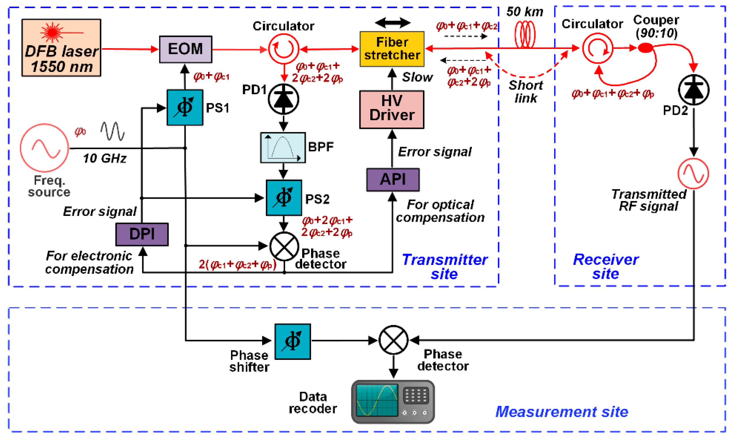
3. Scheme Using Optical–Electronic Joint Phase Compensation

From the demonstration of the frequency transfer with the fiber stretcher-based compensation above, we find that it is difficult to achieve a long-term frequency transfer over a long fiber link by using only optical compensation. To increase the range of phase compensation and ensure the resolution, in this paper, we propose a novel technique of frequency transfer over long fiber link with optical–electronic joint compensation.
The schematic of the fiber-based frequency transfer using the joint compensation is shown in Figure 3. On the transmitter site, we use a commercial distributed feedback laser (DFB) laser as the light source (COFIBER, NLL-1550). The center wavelength of the light source is 1550 nm and the linewidth is about 100 kHz. With a fiber amplifier (COFIBER, ZG-EDFA), the final output optical power is 60 mW. At the same time, we use a signal generator (RS, SMA100B) as the frequency source to generate a 10 GHz RF signal with the power of 18 mW. In the experimental setup, we first phase-shift the RF signal with a timing delay, and then load the signal onto the optical carrier through an EOM. The modulated light passes through a circulator and a fiber stretcher in sequence, where the stretcher introduces another phase delay to the light. The phase-delayed light is sent into a 50-km fiber-optic link. At the end of the link, on the receiver site, the light is received by another circulator and a 90:10 coupler, and the transmitted light is split into two parts. The high-power part is sent back to the fiber link by the circulator, while the remaining light is converted by a high-speed InGaAs photodiode (PD2) into an RF signal that can be used by the users. The returned light on transmitter site with power of ~1 mW passes through the stretcher again, and then is extracted and detected by the circulator and a high-speed photodiode (PD1), respectively. The converted 10 GHz frequency signal with twice phase fluctuations is amplified, phase shifted, and then mixed with the RF reference source signal to generate a phase error signal. The error signal is separated into two parts. One part is fed-back to the fiber stretcher via an analog PI (API) servo controller (AS, NB1005), to compensate the timing fluctuation with a high resolution. The other one is fed-back to the two identical phase shifters via a digital PI (DPI) servo controller, to compensate the phase fluctuations at large range scale. With the two feedback loops, the timing fluctuation introduced in the fiber link can be suppressed at a long-time scale. On the measurement site, the phase fluctuation is obtained by comparing the phase of the frequency signal recovered on the receiver site to the reference signal on the transmitter site. The fluctuation data can be recorded using a digital voltmeter (Keysight, 34461A), which can be further used for stability analysis. Next, the principle of the optical–electronic active phase compensation will be explained in detail.
As shown in Figure 3, the initial phase of the RF signal generated by the frequency source is φ0. After the frequency signal passes through the electronic phase shifter (PS1), an additional phase delay φc1 is added. With the EOM, the phase-delayed RF signal is loaded onto the optical carrier, and the phase of the laser amplitude is φ0 + φc1. The modulated light passes through a circulator and fiber stretcher, and another phase delay φc2 is added. The optical signal is then sent over a 50 km fiber link. During this process, the optical fiber link will bring an extra phase delay to the laser signal due to temperature fluctuations, environmental vibrations, etc. Here, we assume that the phase delay intruded by the fiber link is φp. The total delay of the forward phase after the light is received on the receiver is φf = φ0 + φc1 + φc2 + φp. With the coupler and circulator, part of light is returned to the transmitter through the same fiber link. Since the light has the same optical path in the same fiber and the RF signal will suffer the same phase delay φp,, therefore, the phase delay of the laser signal returning to the transmitter is φr = φ0 + φc1 + φc2 + 2φp. The returning light passes through the fiber stretcher again, thus adding another phase delay φc2. The light is then converted to an RF signal by a photodiode (PD1), which is then phase shifted by another shifter (PS2). The PS1 and PS2 used in our experiment are exactly the same, and they provide the same phase delay. Therefore, the recovered RF signal has a final phase delay φfinal = φ0 + 2φc1 + 2φc2 + 2φp, as shown in Figure 3. We mix the recovered RF signal with the reference source in the mixer to obtain an error signal. Here, the initial phase φ0 in the error signal is eliminated, and only the phase information 2(φc1 + φc2 + φp) is remained. The error signal is divided into two parts, which are fed back to the fiber stretcher and phase shifter, respectively via the API controller and DPI controller. In this case, the phase delay φp has been compensated, as equation 2(φc1 + φc2 + φp) = 0. Compared to previous transfer schemes with a single optical compensator, the proposed frequency transfer system has been greatly improved in terms of resolution and compensation range, thanks to the combined optical and electrical compensation scheme. To verify the feasibility of the proposed scheme, we designed and implemented an actual frequency transfer experiment.

4. Experimental Results

The 50-km long fiber-optic frequency transfer experiment was carried out in our laboratory. In order to keep the environmental influence inside the experiment as consistent as possible with the outside, we opened the windows of the room and introduced wind flow and temperature drift. We estimated that a wide range of timing fluctuations will occur on a 50-km fiber link. Therefore, the electronic and optical joint phase compensator in this experiment could solve the problem of sole optical compensator, and improve the long-term stability of RF transfer.

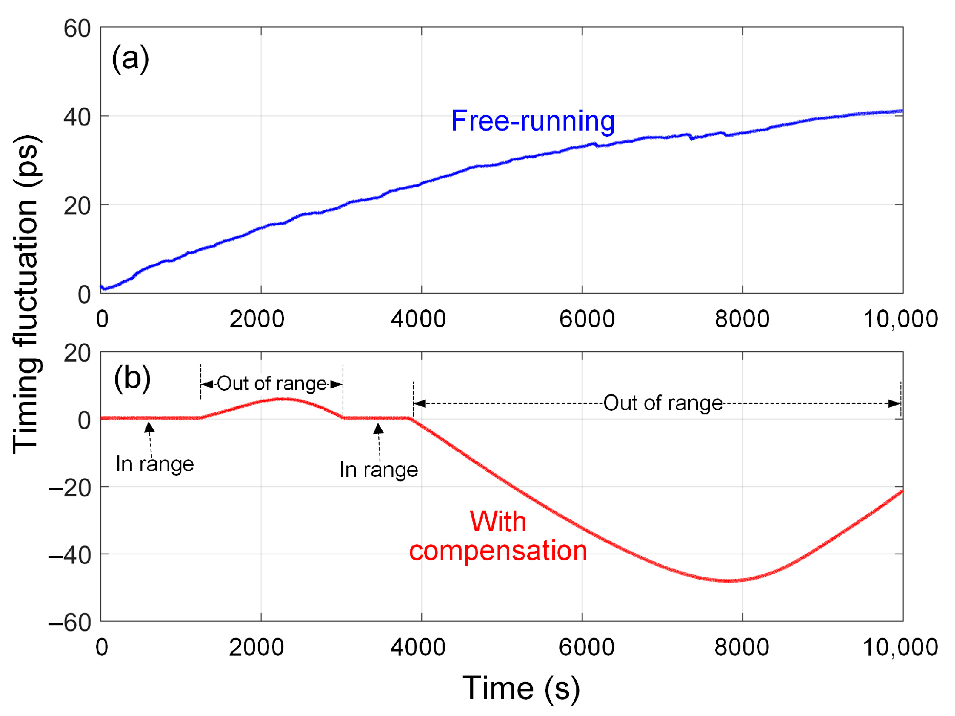
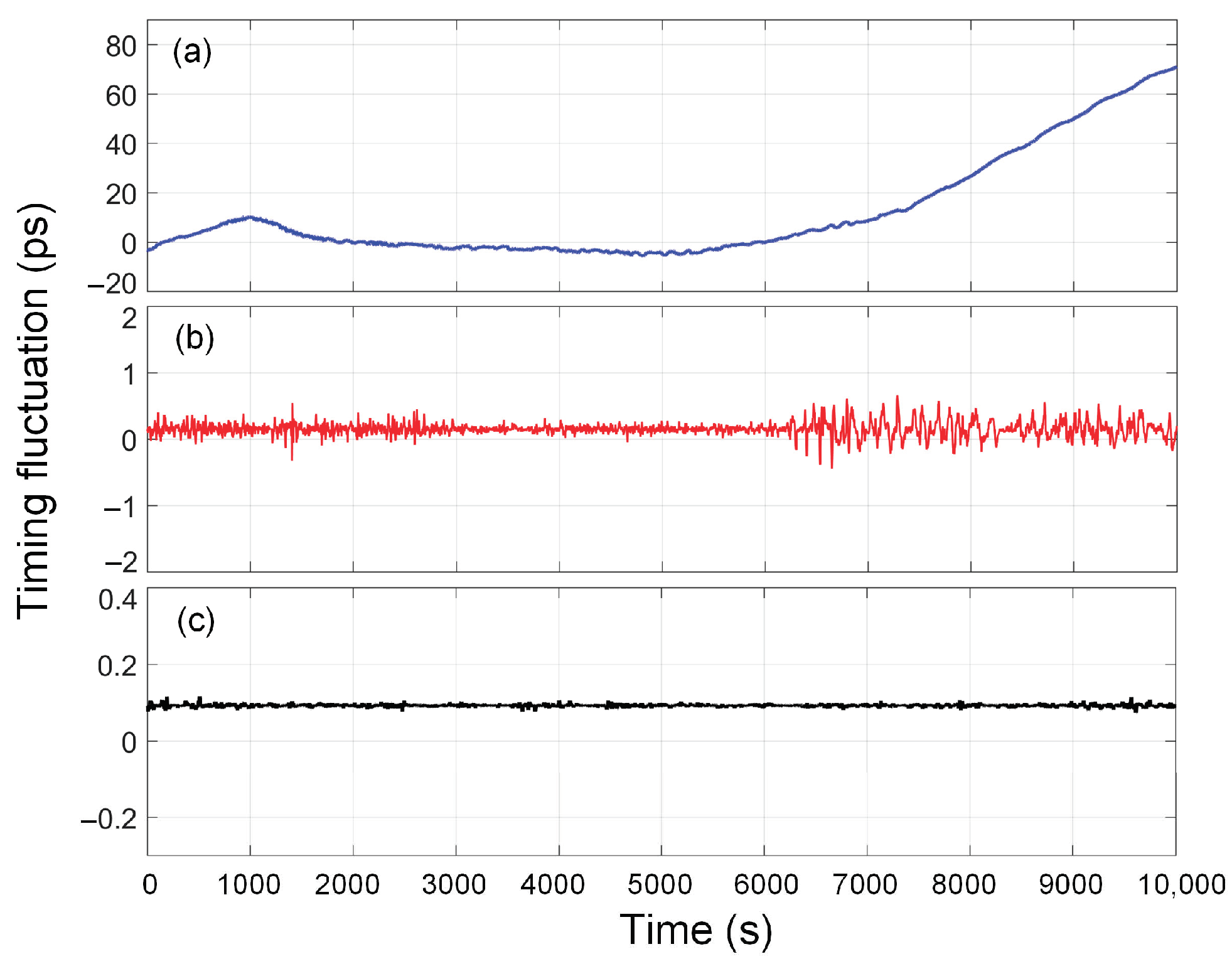
4.1. Timing Fluctuation

Figure 4 shows the timing fluctuation results for our fiber-based frequency transfer experiment. We had measurements for three scenarios, which are the frequency transfers without phase compensation, with phase compensation, and with shorted fiber optic links. Figure 4a shows the timing fluctuation result of the recovered 10 GHz RF signal on the receiver site without phase compensation. Its RMS value is about 21 ps in a 10,000 s measurement time. Figure 4b shows the timing fluctuation result of the recovered RF signal on the receiver site with phase compensation. Its RMS value is about 103 fs in a measurement time of 10,000 s. Comparing these two figures, it can be seen that the timing fluctuation is reduced by about 100 times using our joint phase compensation technique. Figure 4c shows the timing fluctuation result when the optical fiber link is shorted. The shorted link is shown in Figure 3, and it is a 1-m long fiber which directly connects the transmitter and receiver sites, by replacing the 50-km fiber link. Only the noise of the electric and optical components contributes to the result, which can also be regarded as the measurement floor of this system. The RMS value of this floor is about 29 fs in a 10,000 s measurement time.

4.2. Frequency Instability

In order to evaluate the long-term characteristic of the frequency transfer system, we should usually measure the relative fractional frequency stability of the frequency transmission link. In this experiment, we had measured the timing fluctuation of the frequency transfer system shown above, therefore, the Allan deviation of the frequency transfer link can also be calculated as the relative fractional frequency stability. In the same way as in the previous timing fluctuation measurement, the stability measurements have three scenarios, which are the transfers without phase compensation, with phase compensation, and with shorted fiber optic links. Here, Figure 5 shows the stability results of the RF transmission link for three different scenarios. Curve (i) is the stability result without the phase-compensation, showing an Allan deviation of 4.6 × 10⁻¹⁴ at 1 s and 6.3 × 10⁻¹⁵ at 2000 s, respectively. Curve (ii) is the stability result with the phase-compensation, showing an Allan deviation of 2.2 × 10⁻¹⁴ at 1 s, and 8.5 × 10⁻¹⁷ at 2000 s, respectively. Curve (iii) is the Allan deviation of the shorted fiber link, which can be regarded as the measured floor of our system, which is the lower boundary of the stability of our frequency transmission link. This floor is limited only by the noise of the optical and electronic components in the system. Curve (iv) is the frequency stability of a commercial H-master clock (Microsemi, MHM-2010). Comparing curves (i) and (ii), we can find that with the joint phase compensation technique, the long-term stability of the frequency transmission link is much improved by about two orders of magnitude at 2000 s. At the same time, we also found that the frequency stability shown in curve (ii) is superior to H-master at all measurement times from 1 s to 2000 s, which indicates that the optical–electronic joint phase compensation method proposed in this paper can realize the transfer of the atomic clock (Cs clock and H-master) without stability loss in a long-distance fiber link.

5. Discussion

In the section of experimental results above, it is clearly shown that the quality of the transmitted RF signal with the optical–electronic joint compensation is improved significantly. Although some works demonstrate that the timing suppression method with a single optical phase compensator can achieve low-noise frequency transfer, this technique cannot solve the problem of a limited compensation range, as the peak-to-peak timing fluctuation of a long fiber link in long-term scale is very large. At the same time, some works have also reported fiber-based frequency transfer that only use electronic compensation, but it is difficult for the electronic compensation technology to provide high-resolution timing jitter compensation. In order to allow the authors to fully understand the progress of the fiber-based RF transfer techniques, we demonstrate the results of some fiber frequency transfer experiments in recent years, as shown in Table 1. From the table, we can find that when the frequency of the transferred signal is higher than 10 GHz and the fiber length exceeds 50 km, it is difficult to have a technology of fiber-based transfer that can provide timing jitter at the level of a hundred of femtoseconds.
In this paper, we combined an optical fiber stretcher and an electronic phase shifter to build an optical–electronic joint compensator. With the advantages of the large range and high resolution of the joint phase shifter, a long-term and ultra-low jitter frequency transfer over long fiber link was achieved. By contrasting the experimental results of timing fluctuation in a couple of hours with and without phase compensator, it proved that our optical–electronic joint phase compensation method validly suppresses the ambient perturbation introduced timing fluctuation in a long time. In addition, the instability of our frequency transfer is superior to a widely used H-master clock, which indicates that our proposed frequency transfer method can be used to disseminate atomic clocks over long-distance fiber-optic links in long-time scale.
By comparing the commonly used frequency transfer techniques based on microwave communication systems such as GPS and two-way satellite time and frequency transfer (TWSTFT) methods, the fiber-based frequency transfer using phase-compensation has the advantages in cost, accuracy and reliability. First, the power of the laser transceiver components used in the optical frequency transfer system is less than 100 mw, and the power of the electric components and the servo controller is also in the level of watt. The typical microwave communication method requires high-power electronic components. Secondly, the optical frequency transfer can reach the precision of picosecond and femtosecond, while the precision of the microwave communication method can only reach the order of nanosecond. Finally, the radio channel used by microwave communication is far less reliable and safer than the fiber transmission link. Therefore, the fiber-based frequency transfer with phase compensation has become an important and mature approach in the high-precision time-frequency area.

6. Conclusions

A novel fiber-based frequency transfer with optical–electronic joint phase compensation was demonstrated. The joint phase compensation has a significant advantage that it is able to provide not only an ultra-high resolution but also a very wide range. In a frequency transfer experiment, a stable 10 GHz microwave signal was transferred in a 50-km long fiber link with the joint phase compensation, where the RMS timing fluctuation was 103 fs in 10,000 s, and the relative fractional frequency stability of the transmission link was 2.2 × 10⁻¹⁴ at 1 s and 8.5 × 10⁻¹⁷ at 2000 s. Comparing the stabilities of the frequency transfers with and without phase compensation, we can find that with the joint phase compensator, the long-term stability of the frequency transmission link is much improved by about two orders of magnitude at 2000 s. In addition, the stability of the transmission link is much better than even a commercial H-master clock. This indicates that the frequency transfer technique proposed in this paper can be directly applied to the dissemination of most of atomic clock signals in a fiber link. In the future, we will attempt to extend the transmission distance to hundreds of kilometers using phase compensation with a larger dynamic adjustable range.

Author Contributions

Conceptualization, D.H.; methodology, W.H. and Y.L; software, L.F.; hardware, P.Z.; investigation, W.H.; data curation, Y.L.; writing—original draft preparation, W.H. and Y.L.; writing—review and editing, D.H.; supervision, D.H.; project administration, D.H.; funding acquisition, D.H.; W.H. and Y.L. are co-first authors of the article, and they contribute equally to the article. All authors have read and agreed to the published version of the manuscript.

Funding

This research was funded by National Natural Science Foundation of China, grant number 61871084 and 62271109, by Qiandongnan Basic Research Development Program, grant number, 0201007039026, China and by the Equipment Advance Research Field Foundation, grant number 315067207 and 315067206, China.

Institutional Review Board Statement

Not applicable.

Informed Consent Statement

Not applicable.

Data Availability Statement

Date is contained within the article.

Acknowledgments

The authors would like to thank National Natural Science Foundation of China (61871084 and 62271109), Qiandongnan Basic Research Development Program (0201007039026) and the Equipment Advance Research Field Foundation (315067207 and 315067206) for providing funding to carry out the investigation and experiments.

Conflicts of Interest

The authors declare no conflict of interest.

References

  1. Levine, J. A review of time and frequency transfer methods. Metrologia 2008, 45, 162–174. [Google Scholar] [CrossRef]
  2. Predehl, K.; Grosche, G.; Raupach, S.M.F.; Droste, S.; Terra, O.; Alnis, J.; Legero, T.; Hansch, T.W.; Udem, T.; Holzwarth, R.; et al. 920-Kilometer Optical Fiber Link for Frequency Metrology at the 19th Decimal Place. Science 2012, 336, 441–444. [Google Scholar] [CrossRef]
  3. He, Y.; Baldwin, K.G.H.; Orr, B.J.; Warrington, R.B.; Wouters, M.J.; Luiten, A.N.; Mirtschin, D.P.; Tzioumis, T.; Phillips, C.; Stevens, J.; et al. Long-distance telecom-fiber transfer of a radio-frequency reference for radio astronomy. Optica 2018, 5, 138–146. [Google Scholar] [CrossRef] [Green Version]
  4. Li, B.H.; Rizos, C.; Lee, H.K.; Lee, H.K. A GPS-slaved time synchronization system for hybrid navigation. GPS Solut. 2006, 10, 207–217. [Google Scholar] [CrossRef]
  5. Foreman, S.M.; Holman, K.W.; Hudson, D.D.; Jones, D.J.; Ye, J. Remote transfer of ultrastable frequency references via fiber networks. Rev. Sci. Inst. 2007, 78, 021101. [Google Scholar] [CrossRef] [Green Version]
  6. Kim, J.; Cox, J.A.; Chen, J.; Kärtner, F.X. Drift-free femtosecond timing synchronization of remote optical and microwave sources. Nat. Photon. 2008, 2, 733–736. [Google Scholar] [CrossRef]
  7. Musha, M.; Hong, F.L.; Nakagawa, K.; Ueda, K. Coherent optical frequency transfer over 50-km physical distance using a 120-km-long installed telecom fiber network. Opt. Express 2008, 16, 16459–16466. [Google Scholar] [CrossRef]
  8. Williams, P.A.; Swann, W.C.; Newbury, N.R. High-stability transfer of an optical frequency over long fiber-optic links. J. Opt. Soc. Am. B 2008, 25, 1284–1293. [Google Scholar] [CrossRef]
  9. Jiang, H.; Kefelian, F.; Crane, S.; Lopez, O.; Lours, M.; Millo, J.; Holleville, D.; Lemonde, P.; Chardonnet, C.; Amy-Klein, A.; et al. Long-distance frequency transfer over an urban fiber link using optical phase stabilization. J. Opt. Soc. Am. B 2008, 25, 2029–2035. [Google Scholar] [CrossRef] [Green Version]
  10. Grosche, G.; Terra, O.; Predehl, K.; Holzwarth, R.; Lipphardt, B.; Vogt, F.; Sterr, U.; Schnatz, H. Optical frequency transfer via 146 km fiber link with 10−19 relative accuracy. Opt. Lett. 2009, 34, 2270–2272. [Google Scholar] [CrossRef]
  11. Daussy, C.; Lopez, O.; Amy-Klein, A.; Goncharov, A.; Guinet, M.; Chardonnet, C.; Narbonneau, F.; Lours, M.; Chambon, D.; Bize, S.; et al. Long-distance frequency dissemination with a resolution of 10-17. Phys. Rev. E. 2005, 94, 203904. [Google Scholar]
  12. Chen, Y.F.; Jiang, J.; Jones, D.J. Remote distribution of a mode-locked pulse train with sub 40-as jitter. Opt. Express 2006, 14, 12134–12144. [Google Scholar] [CrossRef] [PubMed]
  13. Lopez, O.; Amy-Klein, A.; Daussy, C.; Chardonnet, C.; Narbonneau, F.; Lours, M.; Santarelli, G. 86-km optical link with a resolution of 2 x 10-18 for RF frequency transfer. Eur. Phys. J. D 2008, 48, 35–41. [Google Scholar] [CrossRef] [Green Version]
  14. Kumagai, M.; Fujieda, M.; Nagano, S.; Hosokawa, M. Stable radio frequency transfer in 114 km urban optical fiber link. Opt. Lett. 2009, 34, 2949–2951. [Google Scholar] [CrossRef]
  15. Lenihan, A.S.; Sinkin, O.V.; Marks, B.S.; Tudury, G.E.; Runser, R.J.; Goldman, A.; Menyuk, C.R.; Carter, G.M. Nonlinear timing jitter in an installed fiber network with balanced dispersion compensation. IEEE Photonic. Technol. Lett. 2005, 17, 1558–1560. [Google Scholar] [CrossRef] [Green Version]
  16. Hou, D.; Li, P.; Xi, P.; Zhao, J.; Zhang, Z. Timing jitter reduction over 20-km urban fiber by compensating harmonic phase difference of locked femtosecond comb. Chin. Opt. Lett. 2010, 8, 993–995. [Google Scholar] [CrossRef]
  17. Kim, J.; Chen, J.; Zhang, Z.; Wong, F.N.C.; Kärtner, F.X.; Loehl, F.; Schlarb, H. Long-term femtosecond timing link stabilization using a single-crystal balanced cross correlator. Opt. Lett. 2007, 32, 1044–1046. [Google Scholar] [CrossRef]
  18. Holman, K.W.; Jones, D.J.; Hudson, D.D.; Ye, J. Precise frequency transfer through a fiber network by use of 1.5-mu m mode-locked sources. Opt. Lett. 2004, 29, 1554–1556. [Google Scholar] [CrossRef] [PubMed] [Green Version]
  19. Holman, K.W.; Hudson, D.D.; Ye, J.; Jones, D.J. Remote transfer of a high-stability and ultralow-jitter timing signal. Opt. Lett. 2005, 30, 1225–1227. [Google Scholar] [CrossRef]
  20. Deschenes, J.D.; Sinclair, L.C.; Giorgetta, F.R.; Swann, W.C.; Baumann, E.; Bergeron, H.; Cermak, M.; Coddington, I.; Newburry, N.R. Synchronization of distant optical clocks at the femtosecond level. Phys. Rev. X 2016, 6, 021016. [Google Scholar] [CrossRef] [Green Version]
  21. Hou, D.; Li, P.; Liu, C.; Zhao, J.; Zhang, Z. Long-term stable frequency transfer over an urban fiber link using microwave phase stabilization. Opt. Express 2011, 19, 506–511. [Google Scholar] [CrossRef]
  22. Chen, X.; Zhang, J.; Lu, J.; Lu, X.; Tian, X.; Liu, B.; Wu, H.; Tang, T.; Shi, K.; Zhang, Z. Feed-forward digital phase compensation for long-distance precise frequency dissemination via fiber network. Opt. Lett. 2015, 40, 371–374. [Google Scholar] [CrossRef]
  23. Wang, B.; Zhu, X.; Gao, C.; Bai, Y.; Dong, J.; Wang, L. Square kilometre array telescope—Precision reference frequency synchronisation via 1f-2f dissemination. Sci. Rep. 2015, 5, 13851. [Google Scholar] [CrossRef] [Green Version]
  24. Lessing, M.; Margolis, H.S.; Brown, C.T.A.; Marra, G. Frequency comb-based time transfer over a 159 km long installed fiber network. Appl. Phys. Lett. 2017, 110, 221101. [Google Scholar] [CrossRef] [Green Version]
  25. Ning, B.; Zhang, S.Y.; Hou, D.; Wu, J.T.; Li, Z.B.; Zhao, J.Y. High-precision distribution of highly stable optical pulse trains with 8.8 × 10⁻¹⁹ instability. Sci. Rep. 2014, 4, 5109. [Google Scholar] [CrossRef] [Green Version]
  26. Huang, W.; Li, Z.; Gao, Y.; Hou, D. Fiber-Based Transfer of Radio-Frequency at X-Band with Femtosecond Timing Fluctuation Using Optical Phase Compensation. In Proceedings of the 2021 IEEE 21st International Conference on Communication Technology (ICCT), Tianjin, China, 13–16 October 2021; pp. 1515–1518. [Google Scholar]
  27. Liu, Z.; Xie, W.; Wei, W.; Deng, N.; Dong, Y. Theoretical analysis for fiber-optic distribution of rf signal based on phase-locked loop. Opt. Express 2020, 28, 19851–19863. [Google Scholar] [CrossRef]
  28. Wang, B.; Gao, C.; Chen, W.; Miao, J.; Wang, L. Precise and continuous time and frequency synchronisation at the 5 × 10⁻¹⁹ accuracy level. Sci. Rep. 2012, 2, 556. [Google Scholar] [CrossRef] [Green Version]
  29. Wu, R.; Lin, J.; Jiang, T.; Liu, C.; Yu, S. Stable radio frequency transfer over fiber based on microwave photonic phase shifter. Opt. Express 2019, 27, 38109–38115. [Google Scholar] [CrossRef] [PubMed]
  30. Tian, J.; Li, X.; Ji, Z.; Geng, X.; Mao, Y.; Hou, D. Sub-Hundred-Femtosecond Atmospheric Radio-Frequency Transfer with Frequency Comb Using Fast Optical Phase Compensation. In Proceedings of the 2021 IEEE 21st International Conference on Communication Technology (ICCT), Tianjin, China, 13–16 October 2021; pp. 1500–1503. [Google Scholar]
  31. Guo, G.; Hou, D.; Sun, F.; Liu, K.; Xiao, Y.; Wang, H. Laser-based atmospheric radio-frequency transfer with sub-picosecond timing fluctuation using single phase compensator. Opt. Commun. 2018, 426, 526–530. [Google Scholar] [CrossRef]
  32. Chen, S.; Sun, F.; Bai, Q.; Chen, D.; Chen, Q.; Hou, D. Sub-picosecond timing fluctuation suppression in laser-based atmospheric transfer of microwave signal using electronic phase compensation. Opt. Commun. 2017, 401, 18–22. [Google Scholar] [CrossRef]
  33. Microsemi Corporation. MHM 2010 the World’s Most widely Installed Active Hydrogen Maser for Applications that Require Extreme Frequency Stability, Low Phase Noise and Long Service Life; Microsemi Corporation: San Jose, CA, USA, 2020; Available online: https://www.microsemi.com/product-directory/active-hydrogen-maser/4123-mhm-2010-active-hydrogen-maser (accessed on 10 September 2022).
  34. Ye, J.; Peng, J.L.; Jones, R.J.; Holman, K.W.; Hall, J.L.; Jones, D.J.; Diddams, S.A.; Kitching, J.; Bize, S.; Bergquist, J.C.; et al. Delivery of high-stability optical and microwave frequency standards over an optical fiber network. J. Opt. Soc. Am. B 2003, 20, 1459–1467. [Google Scholar] [CrossRef]
  35. Kim, J.; Ludwig, F.; Felber, M.; Kartner, F.X. Long-term stable microwave signal extraction from mode-locked lasers. Opt. Express 2007, 15, 8951–8959. [Google Scholar] [CrossRef] [PubMed] [Green Version]
  36. Narbonneau, F.; Lours, M.; Bize, S.; Clairon, A.; Santarelli, G.; Lopez, O. High resolution frequency standard dissemination via optical fiber metropolitan network. Rev. Sci. Inst. 2006, 77, 064701. [Google Scholar] [CrossRef]
  37. Marra, G.; Margolis, H.S.; Lea, S.N.; Gill, P. High-stability microwave frequency transfer by propagation of an optical frequency comb over 50 km of optical fiber. Opt. Lett. 2010, 35, 1025–1027. [Google Scholar] [CrossRef]
  38. Wu, Z.L.; Dai, Y.T.; Yin, F.F.; Xu, K.; Li, J.Q.; Lin, J.T. Stable radio frequency phase delivery by rapid and endless post error cancellation. Opt. Lett. 2013, 38, 1098–1100. [Google Scholar] [CrossRef]
  39. Jung, K.; Lim, J.; Shin, J.; Yang, H.; Chen, L.J.; Kartner, F.X.; Kang, H.S.; Min, C.K.; Kim, J. Remote Laser-Microwave Synchronization Over Kilometer-Scale Fiber Link With Few-Femtosecond Drift. J. Lightwave Technol. 2014, 32, 3742–3748. [Google Scholar] [CrossRef]
  40. Wang, X.C.; Liu, Z.W.Y.; Wang, S.W.; Sun, D.N.; Dong, Y.; Hu, W.S. Photonic radio-frequency dissemination via optical fiber with high-phase stability. Opt. Lett. 2015, 40, 2618–2621. [Google Scholar] [CrossRef]
  41. Liang, J.X.; Liu, C.X.; Hu, F.; Zhou, S.J.; Yu, S.; Qiao, Y.J. Stable radio-frequency dissemination system of single wavelength with passive compensation and remote reconstruction. Opt. Commun. 2019, 445, 161–164. [Google Scholar] [CrossRef]
  42. Deng, N.; Wei, W.; Liu, Z.W.Y.; Xie, W.L.; Dong, Y. Distribution of optical-comb-based multi-frequency microwave signals over 100 km optical fiber with high phase stability. Opt. Express 2020, 28, 16634–16643. [Google Scholar] [CrossRef]
  43. Wang, J.L.; Yue, C.L.; Xi, Y.L.; Sun, Y.G.; Cheng, N.; Yang, F.; Jiang, M.Y.; Sun, J.F.; Gui, Y.Z.; Cai, H.W. Fiber-optic joint time and frequency transfer with the same wavelength. Opt. Lett. 2020, 45, 208–211. [Google Scholar] [CrossRef] [Green Version]
  44. Yu, C.L.; Guo, H.; An, Z.Y.; Li, Y.H.; Zheng, Z. Self-referenced distribution of millimeter waves over 10 km optical fiber with high frequency stability. Opt. Lett. 2021, 46, 3949–3952. [Google Scholar] [CrossRef] [PubMed]
Figure 1. Schematic of typical fiber-based frequency transfer with optical compensation. CW: continuous wave, EOM: electro-optical modulator, BPF: band-pass filter, HV: high voltage, PD: photodiode, PI: proportional-integral controller, FFT: fast Fourier transform.
Applsci 12 11262 g001
Figure 2. Timing fluctuation results for RF transfers with and without optical phase compensation. (a) Free-running link without compensation. (b) The link with compensation.
Applsci 12 11262 g002
Figure 3. Schematic of fiber-based RF transfer with optical–electronic joint phase compensation. CW: continuous wave, EOM: electro-optical modulator, PS: phase shifter, BPF: band-pass filter, HV: high voltage, PD: photodiode, API: analog proportional-integral controller. DPI: digital proportional-integral controller.
Applsci 12 11262 g003
Figure 4. Timing fluctuation results. (a) Without phase compensation. (b) With phase compensation. (c) The measurement floor attributed by the short link. The sample rate is 1 point/second for all curves.
Applsci 12 11262 g004
Figure 5. Frequency instability results for the fiber-based RF transfer. (i) Free-running link without phase compensation. (ii) With optical–electronic joint phase compensation. (iii) The measurement floor for the short link. (iv) For H-master clock.
Applsci 12 11262 g005
Table 1. Comparison of different experiments of fiber-based RF transfer.
AuthorsYearOptical/Electronic
Compensation
FrequencyDistanceTiming
Fluctuation
Ye, J. et al. [34]2003Optical1 GHz3.45 km~160 ps (0.5 rad)
Kim, J. et al. [35]2007Optical10.225 GHzShort link~100 fs (3 mrad)
Narbonneau, F. et al. [36]2007Electronic100 MHz2.5 km~1.3 ps (0.3 mrad)
Kim, J. et al. [6]2008Optical10.225 GHz300 m6.8 fs
Kumagai, M. et al. [14]2009Electronic1 GHz114 km30 ps
Marra, G. et al. [37]2010Optical1.5 GHz50 kmNA *
Hou, D. et al. [21]2011Electronic100 MHz80 km16 ps
Wu, Z. et al. [38]2013Electronic2.81 GHz10 km~79 ps (0.05 rad)
Jung, K. et al. [39]2014Optical2.856 GHz610 m2.7 fs
Wang, X. et al. [40]2015Electronic20.07 GHz100 km1 ps
Liang, J. et al. [41]2019Electronic2.4 GHz80 kmNA *
Deng, N. et al. [42]2020Optical10.015 GHz100 km580 fs
Wang, J. et al. [43]2020Electronic1 GHz110 km200 fs
Yu, C. et al. [44]2021Electronic26 GHz10 km160 fs
* Not report.
Publisher’s Note: MDPI stays neutral with regard to jurisdictional claims in published maps and institutional affiliations.

