Article

Study on the Influence of Internal Water Pressure on the Internal Force of Circular Hydraulic Tunnel Lining

1
School of Civil Engineering, Nanjing Forestry University, Nanjing 210037, China
2
Jiangsu Province Key Laboratory of Soil and Water Conservation and Ecological Restoration, Nanjing 210037, China
*
Author to whom correspondence should be addressed.
Appl. Sci. 2022, 12(21), 11271; https://doi.org/10.3390/app122111271
Submission received: 10 October 2022 / Revised: 29 October 2022 / Accepted: 4 November 2022 / Published: 7 November 2022
(This article belongs to the Special Issue Advances in Non-destructive Diagnosis of Masonry)

Abstract

:
The internal water pressure condition influences the internal force of the circular hydraulic tunnel lining. However, calculating the lining’s internal force of this type of tunnel still lacks practical theory. Based on the modified routine method and the theory of structural mechanics, the internal stress model of the tunnel section is established in this paper. The general calculation formula of lining internal force is deduced by considering arbitrary water level height and different water conveyance pressures. The formula is used to calculate the internal force of the lining under the action of internal water pressure and the influence laws of water level height and water conveyance pressure are explored, respectively. In addition, case analysis was carried out for several typical projects. The results show that the maximum internal force of the lining increases with the increase of water pressure and inner radius and the maximum internal force is in a fixed special position when the water is conveyed under pressure. When the water is conveyed without pressure, the internal force of the lining will increase with the increased water level. However, the maximum bending moment and axial force will reduce at the special water level. This calculation theory considering different working conditions of internal water pressure solves the calculation problem of the internal force of a circular hydraulic tunnel. It improves the design theory of tunnel structure and provides a theoretical basis for this type of tunnel’s structural design and safe operation.

1. Introduction

Hydraulic tunnels play a crucial role in regional water transfer, hydropower generation, diversion and flood discharge, etc. Different water-flowing conditions are the key issues for structural design and safe operation [1,2]. According to different stress states, hydraulic tunnels can be divided into non-pressure and pressure tunnels. The water flow in the non-pressure tunnel is open flow and the water level affects the internal force of the lining. The inside of the pressure tunnel is filled with water and the value of water conveyance pressure influences the internal force of the lining [3,4]. Besides, the dynamic characteristics of water in the tunnel and the water seepage of the lining structure will also affect the internal force of the structure [5,6]. At present, there is still a lack of general formula to solve the internal force of lining under different water conveyance conditions.
The modified routine method improves the calculation theory of the routine method by introducing the bending stiffness to effectively consider the reduction effect of the bending stiffness of the joint. It has become a commonly used theoretical method for calculating lining internal force in tunnel structure design [7]. Huang et al. [8] considered the situation that the groundwater level is located in the tunnel section and modified the formula of horizontal displacement of the structure in the modified routine method. This expands the applicable scene of the modified routine method. Dong et al. [9] aim at the problem that the calculation theory of shield segments is insufficient to study the joints. They consider the allowable deformation of the segment joint. The elastic center method and superposition principle are adopted to deduce the calculation formula of lining internal force with the discontinuous joint. Wang et al. [10] introduced a new analytical solution to calculate the internal force and deformation of the circular tunnel lining by using the curved Euler beam theory and the principle of minimum potential energy. This method can consider joints and loads with arbitrary distribution and has remarkable advantages in rigid body displacement treatment and soil reaction calculation. With the emergence of large-diameter and deep tunnels, the traditional design method will certainly impact the internal force calculation because it does not consider the pre-deformation and assembly errors in the segment assembly process. Liu et al. [11] deduced an analytical solution to calculate the internal force of shield lining by assuming the assembly error of bolt holes and the pre-deformation of lining and using the principle of minimum potential energy.
None of the above studies considered the internal force of the lining caused by the internal water pressure of the hydraulic tunnel. However, in actual use, whether in a tunnel with or without pressure, different internal water pressures influence the internal force of the lining [12,13]. This paper refers to internal force positive and negative sign provisions in the modified routine method. The general formula for calculating the internal force of lining under different water levels and water conveyance pressures is derived by using the mechanical analysis method [10,14]. The internal force generated by the lining structure of the tunnel under the external load can be calculated by the modified routine method or other methods [15]. This formula can be superimposed on the formula of internal force caused by external load given by a modified routine method, further improving the application scope of tunnel structure calculation theory.
In this paper, the internal stress calculation model of the tunnel section is established according to structural mechanics theory. The calculation formula of lining internal force is deduced considering any water level height and different water conveyance pressures. Then, using the above formulas, the influence laws of water level and water pressure on the value and distribution of the internal force of tunnel lining are studied. In addition, two typical hydraulic tunnel projects are analyzed and the variation law of lining internal force is obtained. This method can provide a theoretical basis for the structural design and safe operation of hydraulic tunnels.

2. Internal Force Calculation of Lining

In the process of tunnel water conveyance, the lining structure is under the pressure of water and the internal force calculation formulas at different water levels are different. When water is delivered without pressure, there is only the water’s gravity inside the lining. When water is delivered under pressure, the lining bears the water’s gravity and water conveyance pressure. The external rock and soil of the tunnel give the vertical reaction force to the lower part of the lining to counteract the water’s gravity. As the two forces are a pair of interaction forces acting on the lower lining, the influence of water gravity on the lining’s internal force in the vertical direction can be ignored [16,17]. Therefore, it is not necessary to consider the external reaction force of the lining caused by internal water gravity in the vertical direction when calculating with the modified routine method [18]. Taking the pressurized water conveyance tunnel as an example, the calculation model of the internal force of the tunnel section is established, as shown in Figure 1.
In the figure, r is the inner radius of the lining; Hw is the water level height; P is the water conveyance pressure; q is the gravity of the water at the bottom of the tunnel, q = γwHw; γw is the weight of water.
The load and structure on both sides of the tunnel are symmetrical and there is no vertical pressure. The basic system is shown in Figure 2 [8]. The lining is a secondary statically indeterminate structure and the typical equation of the force method is as follows:
δ 11 X 1 + δ 12 X 2 + Δ 1 P = 0 δ 21 X 1 + δ 22 X 2 + Δ 2 P = 0
where δ11, δ12, δ21 and δ22 are the coefficient of the typical equation; ∆1P and ∆2P are the free terms of the typical equation; X1 and X2 are the redundant unknown force.
According to the modified routine method, it is stipulated that the positive and negative signs of internal forces are as follows. The bending moment is positive when the inner side is tension; the axial force is positive when this is compression; the shear force is positive with the counterclockwise direction around the isolator [10,14]. The unit bending moment diagrams M ¯ 1 and M ¯ 2 are shown in Figure 3.
The distribution forms of internal water pressure in pressurized water conveyance and pressureless water conveyance are different, but the basic structure and unit bending moment diagram of internal force calculation in the two cases are the same. Therefore, the formulas for calculating the coefficients and free terms of typical equations in the two water conveyance forms as follows:
δ 11 = 0 π M ¯ 1 2 E I r d θ = π r E I
δ 12 = δ 21 = 0
δ 22 = 0 π M ¯ 2 2 E I r d θ = π r 3 2 E I
Δ 1 P = 0 π M ¯ 1 M P E I r d θ = r E I 0 π M P d θ
Δ 2 P = 0 π M ¯ 2 M P E I r d θ = r 2 E I 0 π M P cos θ d θ
where EI is the bending stiffness, which will be eliminated later; MP is the bending moment produced by water pressure in the basic structure; θ is the angle between the radius at the calculated position and the x-axis.
The coefficients and free terms are substituted into the typical equation and the formulas for calculating the redundant unknown forces X1 and X2 are obtained.
X 1 = 1 π 0 π M P d θ X 2 = 2 π r 0 π M P cos θ d θ
According to the calculation formula of bending moment MP, axial force NP, shear force QP and redundant unknown force produced by water pressure, lining internal force calculation formulas can be obtained.
M θ = X 1 X 2 r cos θ + M P N θ = X 2 cos θ + N P Q θ = X 2 sin θ + Q P
The internal force of the circular lining structure of a water conveyance tunnel under different water conveyance conditions can be calculated by Formula (8). The formulas of MP, NP and QP are determined by the specific distribution of water pressure. The calculation is divided into two cases: pressurized water conveyance and pressureless water conveyance. The corresponding results are substituted into Formula (8) to obtain the internal force calculation formula of the lining structure.

2.1. Pressurized Water Conveyance

When water is delivered under pressure, the water gravity and the water conveyance pressure P act together inside the tunnel lining. According to the basic structure in Figure 2, the structural load diagram under the condition of pressurized water conveyance is established, as shown in Figure 4. The formulas of MP, NP and QP produced by water pressure can be obtained.
M P = 1 12 3 q q cos θ + 6 P r 2 cos 2 θ N P = 1 4 2 q q cos θ + 4 P r cos 2 θ Q P = 1 4 2 q q cos θ + 4 P r sin θ cos θ
Substituting the calculation formula of MP in the above formula into Formula (7), the calculation formula of the redundant unknown force is obtained.
X 1 = 1 8 q + 2 P r 2
X 2 = 1 16 q r
Then, by substituting Formulas (9)–(11) into Formula (8), the lining’s internal force can be obtained when water is delivered under pressure. The formula is as follows:
M θ = 1 8 q + 2 P r 2 + 1 16 q r 2 cos θ + 1 12 3 q q cos θ + 6 P r 2 cos 2 θ N θ = 1 16 q r cos θ 1 4 2 q q cos θ + 4 P r cos 2 θ Q θ = 1 16 q r sin θ 1 4 2 q q cos θ + 4 P r sin θ cos θ

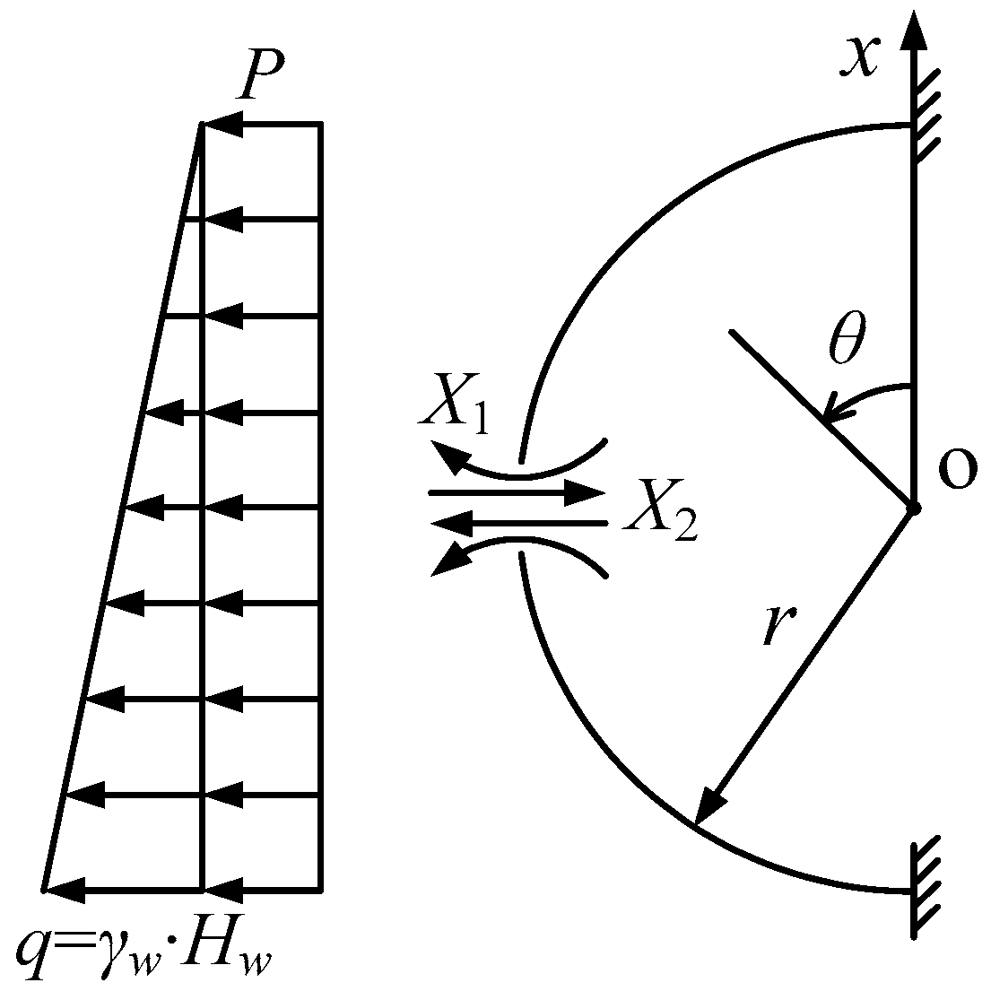
2.2. Pressureless Water Conveyance

When water is delivered without pressure, the inside of the tunnel lining is only affected by the water’s gravity and the calculation of lining internal force is affected by the height Hw of the water level. If the central angle corresponding to the water conveyance height is φ, then cosφ = (Hwr)/r. The internal force calculation formulas corresponding to the water levels at the upper and lower part of the tunnel are different, so the two cases are calculated separately below.

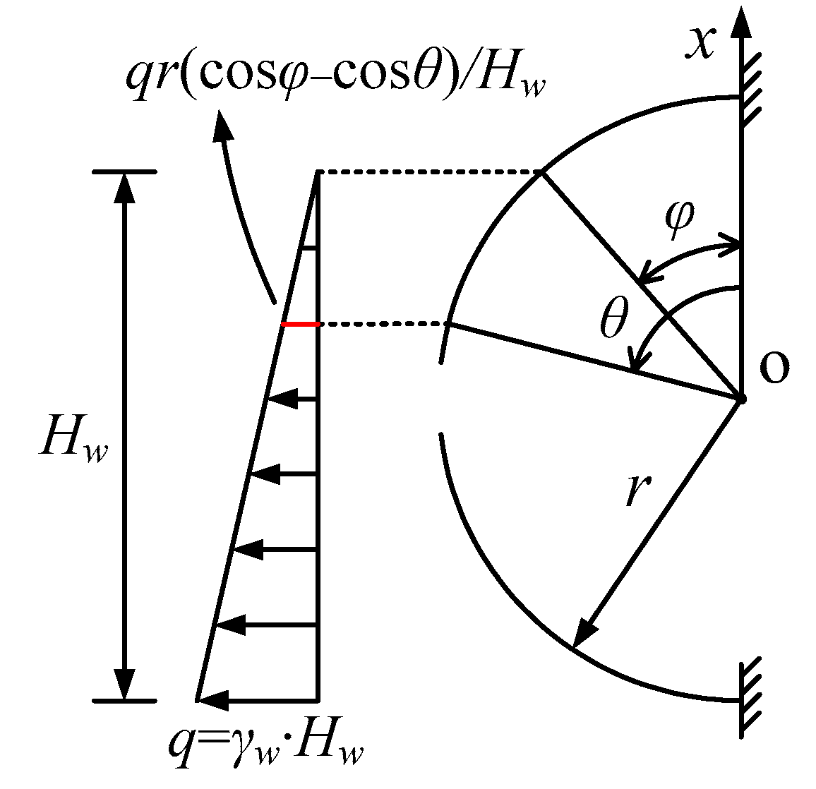
2.2.1. The Water Level Is at the Upper Part of the Tunnel

According to the basic structure in Figure 2, a structural load diagram is established under the condition that the pressureless water level is at the upper part of the tunnel, as shown in Figure 5. The height range of the water level is rHw ≤ 2r and the value range of φ is 0 ≤ φ ≤ π/2.
(1)
when 0 ≤ θφ,
M P = q r 3 cos 2 φ 6 H w 3 cos θ cos φ N P = q r 2 cos 2 φ 2 H w cos θ Q P = q r 2 cos 2 φ 2 H w sin θ
(2)
when φθ ≤ π,
M P = q r 3 cos 2 θ 6 H w 3 cos φ cos θ N P = q r 2 cos 2 θ 2 H w 2 cos φ cos θ Q P = q r 2 sin θ cos θ 2 H w 2 cos φ cos θ
Substituting the formulas of MP in Formulas (13) and (14) into Formula (7), the formulas of the redundant unknown force are obtained.
X 1 = q r 3 36 π H w 6 φ cos 3 φ 9 cos 2 φ sin φ 9 π φ cos φ 6 sin φ + 2 sin 3 φ
X 2 = q r 2 24 π H w 5 cos 3 φ sin φ + 12 φ cos 2 φ 20 cos φ sin φ + 7 cos φ sin 3 φ 3 π φ
Then, by substituting Formulas (13)–(16) into Formula (8), the lining internal force can be obtained when the water level of the pressureless water conveyance is at the upper part of the tunnel. The formula is as follows:
(1)
when 0 ≤ θφ,
M θ = X 1 X 2 r cos θ + q r 3 cos 2 φ 6 H w 3 cos θ cos φ N θ = X 2 cos θ q r 2 cos 2 φ 2 H w cos θ Q θ = X 2 sin θ q r 2 cos 2 φ 2 H w sin θ
(2)
when φθ ≤ π,
M θ = X 1 X 2 r cos θ + q r 3 cos 2 θ 6 H w 3 cos φ cos θ N θ = X 2 cos θ q r 2 cos 2 θ 2 H w 2 cos φ cos θ Q θ = X 2 sin θ q r 2 sin θ cos θ 2 H w 2 cos φ cos θ

2.2.2. The Water Level Is at the Lower Part of the Tunnel

According to the basic structure in Figure 2, a structural load diagram is established under the condition that the pressureless water level is at the lower part of the tunnel, as shown in Figure 6. The height range of the water level is 0 ≤ Hwr and the value range of the central angle φ corresponding to the water conveyance height position is π/2 ≤ φ ≤ π.
(1)
when 0 ≤ θφ,
M P = 0 N P = 0 Q P = 0
(2)
when φθ ≤ π,
M P = q r 3 6 H w cos φ cos θ 3 N P = q r 2 cos θ 2 H w cos φ cos θ 2 Q P = q r 2 sin θ 2 H w cos φ cos θ 2
Substituting the formulas of MP in Formulas (19) and (20) into Formula (7), the formulas of the redundant unknown force are obtained.
X 1 = q r 3 36 π H w 6 π φ cos 3 φ + 9 cos 2 φ sin φ + 9 π φ cos φ + 6 sin φ 2 sin 3 φ
X 2 = q r 2 24 π H w 5 cos 3 φ sin φ 12 π φ cos 2 φ 20 cos φ sin φ + 7 cos φ sin 3 φ 3 π φ
Then, by substituting Formulas (19)–(22) into Formula (8), the lining internal force can be obtained when the water level is at the lower part of the tunnel. The formula is as follows:
(1)
when 0 ≤ θφ,
M θ = X 1 X 2 r cos θ N θ = X 2 cos θ Q θ = X 2 sin θ
(2)
when φθ ≤ π,
M θ = X 1 X 2 r cos θ + q r 3 6 H w cos φ cos θ 3 N θ = X 2 cos θ + q r 2 cos θ 2 H w cos φ cos θ 2 Q θ = X 2 sin θ + q r 2 sin θ 2 H w cos φ cos θ 2

3. Analysis of the Influence of Water Conveyance Pressure on Lining Internal Force

The lining structure design of traffic tunnels, municipal tunnels and mine tunnels mainly consider the external water and soil pressure. At this time, the internal force of the lining can be effectively calculated by using the modified routine method [19,20,21]. The effect of common internal loads is not significant, so no extra consideration is needed. The interior of the hydraulic tunnel is usually filled with water or even pressurized water, which leads to obvious changes in the internal force of the lining. Therefore, water conveyance pressure and water conveyance level are important indexes for the normal operation of hydraulic tunnels [22,23]. In the following, the formula in Section 2 is used to calculate the lining internal force under the action of water pressure. Further, the influence laws of pressurized water conveyance pressure and pressureless water conveyance level are studied respectively.

3.1. Influence of Pressurized Water Conveyance Pressure on Lining Internal Force

Hydraulic tunnel pressurized water conveyance will change the value and distribution of lining internal force. Here, the variation law of lining internal force is analyzed according to different water conveyance pressures. The water conveyance pressure of the built hydraulic tunnel is generally less than 1 MPa and the section size is determined according to the water demand and technical and economic comparison [24].

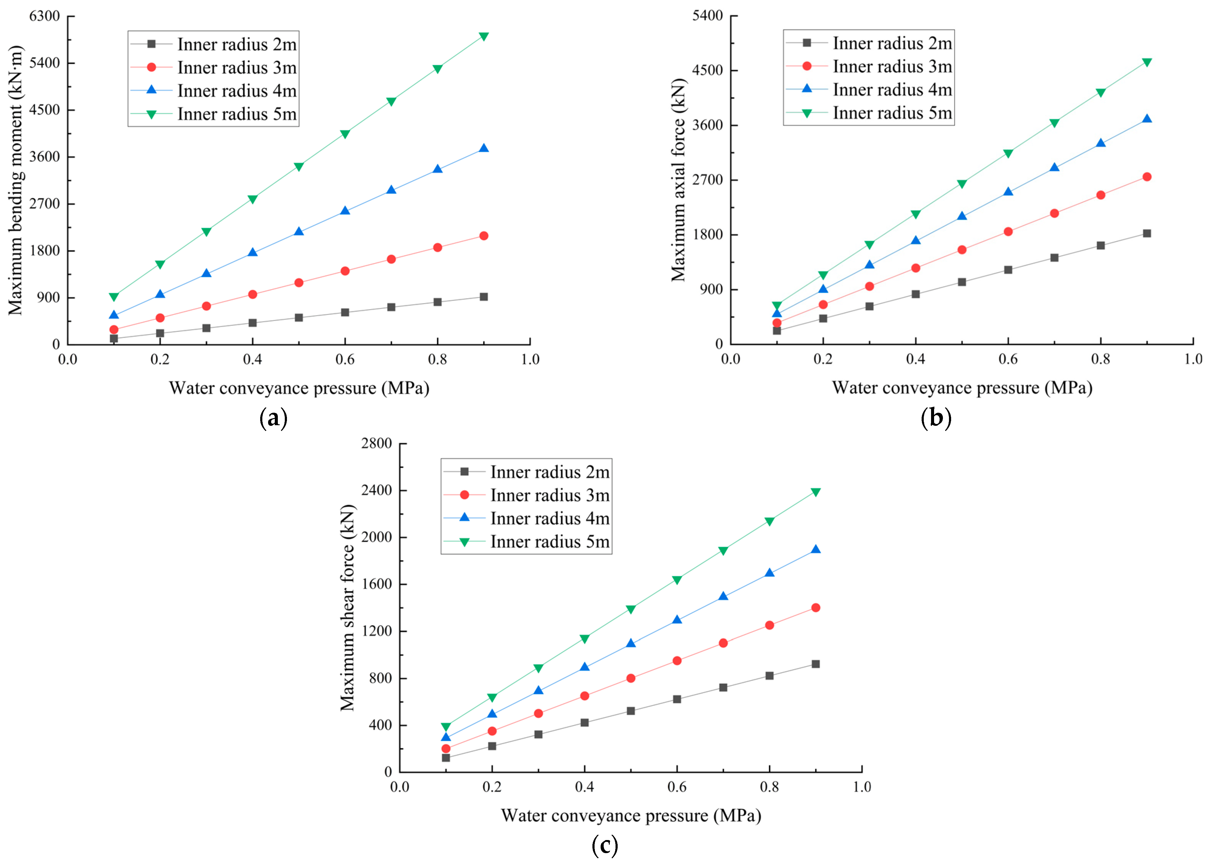
3.1.1. Influence of Water Conveyance Pressure on the Maximum Internal Force of Lining

In order to reveal the influence of water conveyance pressure on the maximum internal force of the lining, four working conditions are selected with tunnel inner radii of 2, 3, 4 and 5 m. The maximum internal force under the water conveyance pressure of 0.1, 0.2, 0.3, 0.4, 0.5, 0.6, 0.7, 0.8 and 0.9 MPa were calculated, respectively. The positive and negative value of internal force only indicates the direction of the force. The bending moment and shear force are the maxima of absolute value and the axial force is the inverse of the minimum value (i.e., the maximum axial tension). The curve of the maximum internal force with water conveyance pressure under four lining sizes is shown in Figure 7.
It can be seen from Figure 7 that the maximum internal force of the lining will increase with the increase of water conveyance pressure and inner radius. The larger the inner radius of the lining, the more significant the influence of water conveyance pressure on the maximum internal force. Under the same water conveyance pressure, the influence of changing the inner radius on the bending moment is greater than that on axial force and shear force. This shows that, when the hydraulic tunnel has high requirements for water-passing capacity, the internal force borne by the lining is large, so it is necessary to strengthen the design of structural strength.

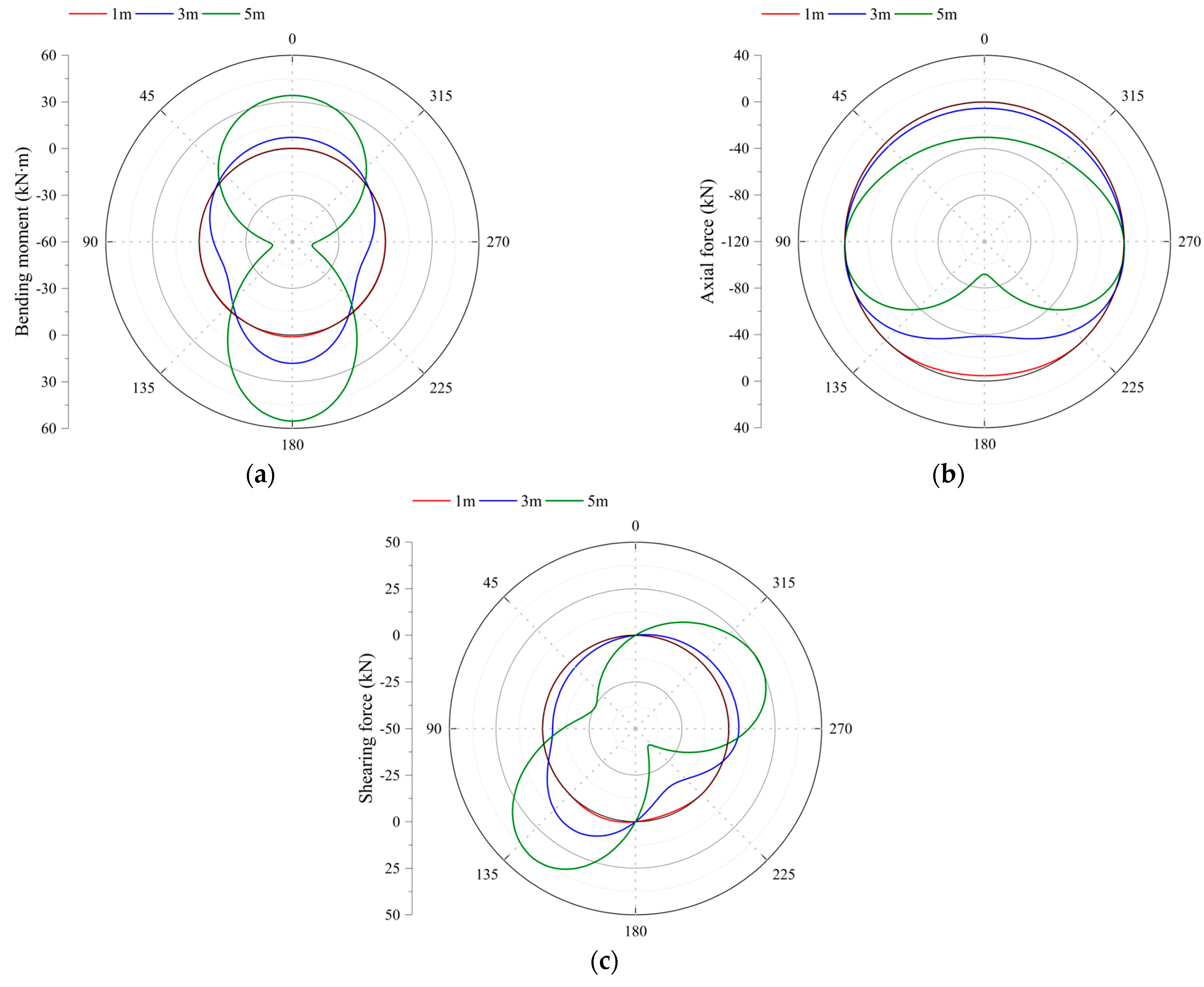
3.1.2. Influence of Water Conveyance Pressure on Internal Force Distribution of Lining

In order to analyze the influence of water conveyance pressure on the internal force distribution of lining, a tunnel with an inner radius of 3 m is taken as an example. The internal force values of lining at different angles under the water conveyance pressure of 0.1, 0.3 and 0.5 MPa are calculated, respectively. The distribution of lining internal force value with angle under three water conveyance pressure conditions is shown in Figure 8.
It can be seen from Figure 8a that the bending moments of lining structures at 45°, 135°, 225° and 315° are almost zero under different water conveyance pressures. Taking this as the dividing point, the lining is divided into four sections: upper, lower, left and right. The inner sides of the upper and lower sections of the lining and the outer sides of the left and right sections of the lining are in tension. It can be seen from Figure 8b that, under the action of internal water pressure, the lining structure will not produce axial pressure. Further, the axial force distribution shows that, the closer it is to both sides of the lining, the smaller the axial tension will be. It can be seen from Figure 8c that, under the action of different water conveyance pressures, the shear force at the position where the bending moment is zero produces the maximum value. Further, the shear force at the upper, lower, left and right endpoints of the lining are almost zero. To sum up, the lining internal force distribution shows a certain change rule with the increase of water conveyance pressure. Among these, the maximum value of internal force is in the special position which is different from 0 degrees angle by 45 degrees multiple angles.

3.2. Influence of Pressureless Water Conveyance Level on Lining Internal Force

The value and distribution of the lining internal force of a pressureless hydraulic tunnel are greatly influenced by the water level. Here, the variation law of lining internal force is analyzed according to different water levels.

3.2.1. Influence of Water Conveyance Level on the Maximum Internal Force of Lining

To reveal the influence of water level on the maximum internal force of lining, four working conditions are selected of tunnel inner radii 2, 3, 4 and 5 m. The maximum internal force is calculated by taking an analysis point at an interval of 1 m from 1 m water level to full water level height. The positive and negative value of internal force only indicates the direction of force, and the selection of the maximum value of each internal force is the same as that in Section 3.1.1. The curve of the maximum internal force with water conveyance level under different lining sizes is shown in Figure 9.
It can be seen from Figure 9a that, when the water level exceeds half the height of the tunnel, the maximum bending moment will decrease in the local water level section. Then the maximum bending moment continues to increase and the increase rate gradually increases. It can be seen from Figure 9b that the maximum axial force of the lining will decrease abnormally under the condition of full water level. Before that, the maximum axial force increased with the increase in water level. It can be seen from Figure 9c that the maximum value of lining shear force increases with the increase of water level height and the increase rate gradually increases. In addition, at the same water level, the maximum internal force of the lining is affected little by the inner radius. The maximum internal force of the lining of a pressureless water conveyance tunnel is much smaller than that of a pressurized water conveyance tunnel. Therefore, designing the tunnels with the same water conveyance capacity can comprehensively compare two design schemes: pressurized water conveyance and increased-size pressureless water conveyance.

3.2.2. Influence of Water Conveyance Level on Internal Force Distribution of Lining

To analyze the influence of water level on the internal force distribution of lining, a tunnel with an inner radius of 3 m is taken as an example and the internal force values of lining at different angles at 1, 3 and 5 m water levels are calculated, respectively. Figure 10 shows the distribution of lining internal force values with angles under three water levels.
It can be seen from Figure 10 that the higher the water conveyance level, the more obvious the difference in internal force values at different angles of the lining. When the water level is 1 m, the internal force of the lining is small. Then the internal force increases with the increase in water level. Under different water levels, the maximum values of bending moment and axial force are always at the bottom of the lining and the shear forces at the upper and lower ends of the lining are always 0. When pressureless water conveyance is compared with pressurized water conveyance, the internal force of the former is much smaller than that of the latter and the distribution of the former is more irregular due to the influence of water level height.

4. Case Analysis

Hydraulic tunnels can be broadly divided into diversion tunnels and drainage tunnels according to their uses. The diversion tunnels supply water resources to places that need water for power generation, irrigation, production and for living purposes. The drainage tunnels discharge water to the designated position, which plays the role of flood discharge and sewage discharge [25]. A typical hydraulic tunnel project is selected in the diversion tunnel and the discharge tunnel, respectively. The internal force of the lining under different water pressures is calculated, considering only the internal water pressure.

4.1. Water Conveyance Tunnel of Raw Water Project of Qingcaosha Water Source Area

The raw water project of the Qingcaosha water source area will transfer the high-quality freshwater resources of the Qingcaosha reservoir to Shanghai. The water pipeline is mainly composed of the Changxing island water tunnel and the river-crossing tunnel. The project provides a large amount of raw water supply for Shanghai through the water conveyance tunnel. With a daily water supply of over 70,000 cubic meters and a beneficiary population of over 10 million, the regional water transfer efficiency is important. This project is the first time in China that a single-layer lining shield method is used to build a water conveyance tunnel. The tunnel across the river is 7.29 m long, the inner radius of the lining is 2.92 m, the outer radius is 3.4 m and the strength grade of segment concrete is C55 [26,27]. With the calculation formula in Section 2, the maximum value of the internal force of the lining structure at half-water level, full-water level and pressurized water conveyance is calculated under the action of internal water pressure only, as shown in Table 1.
According to the data in Table 1, the internal force of the lining of this water conveyance tunnel is small when pressureless water conveyance and the structural safety factor is high at this time. The maximum internal force of pressurized water conveyance is much larger than that of pressureless water conveyance. Under the action of 0.4 MPa water pressure, the maximum axial tensile force of the lining is 1220.2 kN and the maximum axial tensile stress is 2.54 MPa. Therefore, analyzing only the internal water pressure, the maximum water conveyance pressure that the water conveyance tunnel can bear is about 0.3 MPa, but considering that the external load can offset some of the internal water pressure, the actual water conveyance pressure that can be borne is larger than this value.

4.2. Yangqu Hydropower Station Flood Discharge Tunnel

Yangqu Hydropower Station is a large-scale hydropower hub project which mainly generates electricity. It started construction in December 2021 and is currently in the construction stage. The project is mainly composed of a river-blocking rockfill dam, a flood discharge tunnel on the left bank and a water diversion and power generation building on the right bank. Among these, the flood discharge tunnel is 467 m long and its permanent support adopts a C25 reinforced concrete circular lining with an inner radius of 5.3 m and a thickness of 0.5 m [28,29]. With the calculation formula in Section 2, the maximum value of the internal force of the lining structure at half-water level, full-water level and pressurized water conveyance is calculated under the action of only internal water pressure, as shown in Table 2.
According to the data in Table 2, due to the large cross-section size of the flood discharge tunnel, the internal force generated by the lining during pressurized water conveyance is large. Under the pressure of 0.2 MPa, the maximum axial tensile force of the lining reaches 1231.7 kN and the maximum axial tensile stress is 2.46 MPa, which is much higher than the tensile strength of C25 concrete. In addition, the maximum bending moment when discharging water under pressure is also very large. Therefore, the flood discharge tunnel should avoid generating water pressure inside.

5. Conclusions

In this paper, according to the different water conveyance conditions of the hydraulic tunnel, the theoretical method of calculating the internal force of the lining structure is given by using the mechanical analysis method. With this calculation method, the influence law of water level height and water conveyance pressure on the maximum value and distribution of lining internal force is further analyzed. The main conclusions are as follows:
(1)
The hydraulic tunnel is greatly affected by the internal water pressure. This paper introduces the theory of structural mechanics, considers the operating conditions of different water levels and water conveyance pressures and derives a general formula for calculating the internal force of the lining structure. This calculation method can effectively calculate the value and distribution of internal forces. Based on the modified routine method, the calculation theory of tunnel structure is further improved, which provides a theoretical basis for the design and safe operation of hydraulic tunnels.
(2)
When water is delivered under pressure, the maximum internal force of the lining increases with the increase of water conveyance pressure and inner radius. When water is delivered without pressure, the maximum bending moment and axial force of the lining will inverse the increasing trend at the special water level. In addition, the maximum value of lining internal force of pressureless water conveyance is much smaller than that of pressurized water conveyance. Therefore, when the hydraulic tunnel has high requirements for water-passing capacity, it can strengthen the structural strength to carry out pressurized water conveyance or adopt the design scheme of increasing size and the carrying out of pressureless water conveyance.
(3)
When water is delivered under pressure, the distribution of lining internal force changes regularly with the increase of water conveyance pressure. The maximum value of internal force is in the fixed special position. When water is delivered without pressure, with the increase in water conveyance level the internal force value of the lining increases continuously and the difference in internal force value at different angles is more significant. The internal force of the lining is much stronger when water is delivered under pressure than when water is delivered without pressure, so the strength of the lining structure should be designed to be larger.
(4)
The calculation model ignores both the influence of internal water pressure in the vertical direction and the dynamic characteristics, which is inconsistent with the actual situation. In addition, the mechanism of abnormal maximum bending moment and axial force at special water levels is unclear. These problems need further study.

Author Contributions

Conceptualization, Y.Z.; methodology, Y.Z.; validation, Y.Z. and C.L.; investigation, Y.Z.; resources, Y.Z. and C.L.; writing—original draft preparation, Y.Z.; writing—review and editing, Y.Z.; funding acquisition, Y.Z. and C.L. All authors have read and agreed to the published version of the manuscript.

Funding

This work was supported by the National Natural Science Foundation of China (Grant No. 51508278).

Institutional Review Board Statement

Not applicable.

Informed Consent Statement

Not applicable.

Data Availability Statement

The original contributions presented in the study are included in the article, further inquiries can be directed to the corresponding authors.

Conflicts of Interest

The authors declare no conflict of interest.

References

  1. Andjelkovic, V.; Lazarevic, Z.; Nedovic, V.; Stojanovic, Z. Application of the pressure grouting in the hydraulic tunnels. Tunn. Undergr. Sp. Tech. 2013, 37, 165–179. [Google Scholar] [CrossRef]
  2. Rasouli, M. Engineering geological studies of the diversion tunnel, focusing on stabilization analysis and support design, Iran. Eng. Geol. 2009, 108, 208–224. [Google Scholar] [CrossRef]
  3. Zeng, K.; Xu, J. Unified semi-analytical solution for elastic-plastic stress of deep circular hydraulic tunnel with support yielding. J. Cent. South Univ. 2013, 20, 1742–1749. [Google Scholar] [CrossRef]
  4. Zhou, Y.; Su, K.; Wu, H. Hydro-mechanical interaction analysis of high pressure hydraulic tunnel. Tunn. Undergr. Sp. Tech. 2015, 47, 28–34. [Google Scholar] [CrossRef]
  5. Ahmad, S.; Naji, A.M.; Hussain, I.; Rehman, H.; Yoo, H. Ground saturation response during first filling of lined pressure tunnels: A case study. Rock Mech. Rock Eng. 2021, 54, 513–535. [Google Scholar] [CrossRef]
  6. Rehman, H.; Naji, A.M.; Nam, K.; Ahmad, S.; Muhammad, K.; Yoo, H.K. Impact of construction method and ground composition on headrace tunnel stability in the Neelum–Jhelum hydroelectric project: A case study review from pakistan. Appl. Sci. 2021, 11, 1655. [Google Scholar] [CrossRef]
  7. Do, N.A.; Dias, D.; Oreste, P.P.; Djeran-Maigre, I. Internal forces in segmental tunnel linings—A comparison between current design methods. J. Min. Sci. 2014, 50, 326–334. [Google Scholar] [CrossRef]
  8. Huang, Q.F.; Yuan, D.J.; Wang, M.S. Study on the influence of water level on the internal force of shield tunnel segment structure. J. Geotech. Eng. 2008, 30, 1112–1120. (In Chinese) [Google Scholar]
  9. Dong, L.; Yang, Z.; Wang, Z.; Ding, Y.; Qi, W. Study on internal force of tunnel segment by considering the influence of joints. Adv. Mater. Sci. Eng. 2020, 2020, 1020732. [Google Scholar] [CrossRef]
  10. Wang, J.; Huang, W.; Xu, R.; Yang, Z.; Xu, R. Analytical approach for circular-jointed shield tunnel lining based on the state space method. Int. J. Numer. Anal. Met. 2020, 44, 575–595. [Google Scholar] [CrossRef]
  11. Liu, M.; Liao, S.; Xu, J.; Men, Y. Analytical solutions and in-situ measurements on the internal forces of segmental lining produced in the assembling process. Transp. Geotech. 2021, 27, 100478. [Google Scholar] [CrossRef]
  12. Gurocak, Z. Analyses of stability and support design for a diversion tunnel at the Kapikaya dam site, Turkey. B. Eng. Geol. Environ. 2010, 70, 41–52. [Google Scholar] [CrossRef]
  13. Gurocak, Z.; Solanki, P.; Zaman, M.M. Empirical and numerical analyses of support requirements for a diversion tunnel at the Boztepe dam site, eastern Turkey. Eng. Geol. 2007, 91, 194–208. [Google Scholar] [CrossRef]
  14. Takano, Y.H. Guidelines for the Design of Shield Tunnel Lining. Tunn. Undergr. Sp. Tech. 2000, 15, 303–331. [Google Scholar] [CrossRef]
  15. Carranza-Torres, C.; Diederichs, M. Mechanical analysis of circular liners with particular reference to composite supports. For example, liners consisting of shotcrete and steel sets. Tunn. Undergr. Sp. Tech. 2009, 24, 506–532. [Google Scholar] [CrossRef]
  16. Huang, X.; Zhu, Y.; Zhang, Z.; Zhu, Y.; Wang, S.; Zhuang, Q. Mechanical behaviour of segmental lining of a sub-rectangular shield tunnel under self-weight. Tunn. Undergr. Sp. Tech. 2018, 74, 131–144. [Google Scholar] [CrossRef]
  17. Gu, S.; Sun, G.; Su, P. Computational model of outer circle and inner ellipse shield tunnel lining structure. Adv. Civ. Eng. 2021, 2021, 2303140. [Google Scholar] [CrossRef]
  18. Zhao, C.; Alimardani Lavasan, A.; Barciaga, T.; Kämper, C.; Mark, P.; Schanz, T. Prediction of tunnel lining forces and deformations using analytical and numerical solutions. Tunn. Undergr. Sp. Tech. 2017, 64, 164–176. [Google Scholar] [CrossRef]
  19. Hu, X.; Zhang, Z.; Teng, L. An analytical method for internal forces in DOT shield-driven tunnel. Tunn. Undergr. Sp. Tech. 2009, 24, 675–688. [Google Scholar] [CrossRef]
  20. Jiang, H.; Zhou, S.; Di, H.; Ye, W.; Liu, Z.; Zhao, Y. Earth Pressure and Internal Forces of Tunnel Lining in Jet Grouting Reinforced Mud Stratum. KSCE J. Civ. Eng. 2021, 25, 4005–4017. [Google Scholar] [CrossRef]
  21. Bilotta, E.; Russo, G. Internal Forces Arising in the Segmental Lining of an Earth Pressure Balance-Bored Tunnel. J. Geotech. Geoenviron. 2013, 139, 1765–1780. [Google Scholar] [CrossRef]
  22. Wang, X.; Behbahani, S.S.; Iseley, T.; Azimi, M.; Wei, X.; Wei, G.; Shi, Y. Vertical tunneling in China-A case study of a hydraulic tunnel in Beihai. Tunn. Undergr. Sp. Tech. 2021, 107, 103650. [Google Scholar] [CrossRef]
  23. Zheng, X.Y.; Shen, J. Research on Life Cycle Monitoring of Long Distance Diversion Tunnel Based on NFC Context-Awareness. Geotech. Geol. Eng. 2015, 33, 947–958. [Google Scholar] [CrossRef]
  24. Zhu, Y.; Liu, C. Study on Parameter Influence of New Composite Lining of Water Conveyance Tunnel Under High Internal Water Pressure. Front. Earth Sc Switz. 2022, 10, 920230. [Google Scholar] [CrossRef]
  25. Zhu, Y.; Liu, C.; Yin, X.; Zhang, J. Analysis of the Internal Force and Deformation Characteristics of Double-Layer Lining Structure of Water Conveyance Tunnel. Geofluids 2022, 2022, 9159632. [Google Scholar] [CrossRef]
  26. Yan, Z.G.; Peng, Y.C.; Ding, W.Q.; Zhu, H.H.; Huang, F. Experimental study on single-layer lining segment joint load of water conveyance tunnel in Qingcaosha water source source project. J. Geotech. Eng. 2011, 33, 1385–1390. (In Chinese) [Google Scholar]
  27. Yu, H.; Yuan, Y.; Bobet, A. Seismic analysis of long tunnels: A review of simplified and unified methods. Undergr. Space 2017, 2, 73–87. [Google Scholar] [CrossRef]
  28. Wang, T.; Wu, H.; Li, Y.; Gui, H.; Zhou, Y.; Chen, M.; Zhao, X. Stability analysis of the slope around flood discharge tunnel under inner water exosmosis at Yangqu hydropower station. Comput. Geotech. 2013, 51, 1–11. [Google Scholar] [CrossRef]
  29. Ren, X.P. Finite Element Analysis of Surrounding Rock Stability of Yangqu Hydropower Station. J. Water Resour. Water Eng. 2014, 25, 211–214, 218. (In Chinese) [Google Scholar]
Figure 1. Diagram of internal load in the section of pressurized water conveyance tunnel.
Applsci 12 11271 g001
Figure 2. Basic system for internal force calculation of pressurized water conveyance tunnel.
Applsci 12 11271 g002
Figure 3. Bending moment diagram under unit force. (a) M ¯ 1 diagram ( M ¯ 1 = 1 ). (b) M ¯ 2 diagram ( M ¯ 2 = r · cos θ ).
Applsci 12 11271 g003
Figure 4. Load diagram of pressurized water conveyance.
Applsci 12 11271 g004
Figure 5. Load diagram of the water level at the upper part of the tunnel.
Applsci 12 11271 g005
Figure 6. Load diagram of the water level at the lower part of the tunnel.
Applsci 12 11271 g006
Figure 7. Influence of pressurized water conveyance pressure on the maximum internal force of lining. (a) Maximum bending moment. (b) Maximum axial force. (c) Maximum shear force.
Applsci 12 11271 g007
Figure 8. Influence of pressurized water conveyance pressure on internal force distribution of lining. (a) Bending moment distribution diagram. (b) Axial force distribution diagram. (c) Shear force distribution diagram.
Applsci 12 11271 g008
Figure 9. Influence of pressureless water conveyance level on the maximum internal force of lining. (a) Maximum bending moment. (b) Maximum axial force. (c) Maximum shear force.
Applsci 12 11271 g009
Figure 10. Influence of water conveyance level without pressure on internal force distribution of lining. (a) Bending moment distribution diagram. (b) Axial force distribution diagram. (c) Shear force distribution diagram.
Applsci 12 11271 g010
Table 1. The maximum internal force of water conveyance tunnel lining.
Maximum Internal ForcePressureless Water Conveyance LevelPressurized Water Conveyance Pressure
Half Water LevelFull Water Level0.2 MPa0.4 MPa
Bending moment (kN∙m)16.862.8487.6913.8
Axial force (kN)36.652.2636.21220.2
shearing force (kN)13.250.2341.4633.3
Table 2. The maximum internal force of flood discharging tunnel lining.
Maximum Internal ForcePressureless Water Conveyance LevelPressurized Water Conveyance Pressure
Half Water LevelFull Water Level0.2 MPa0.4 MPa
Bending moment (kN∙m)100.4376.01771.63175.1
Axial force (kN)120.8172.01231.72291.7
shearing force (kN)43.5165.5693.01222.6
Publisher’s Note: MDPI stays neutral with regard to jurisdictional claims in published maps and institutional affiliations.

