

Development of a Metasilencer Considering Flow in HVAC Systems
Abstract
:1. Introduction
2. Theory
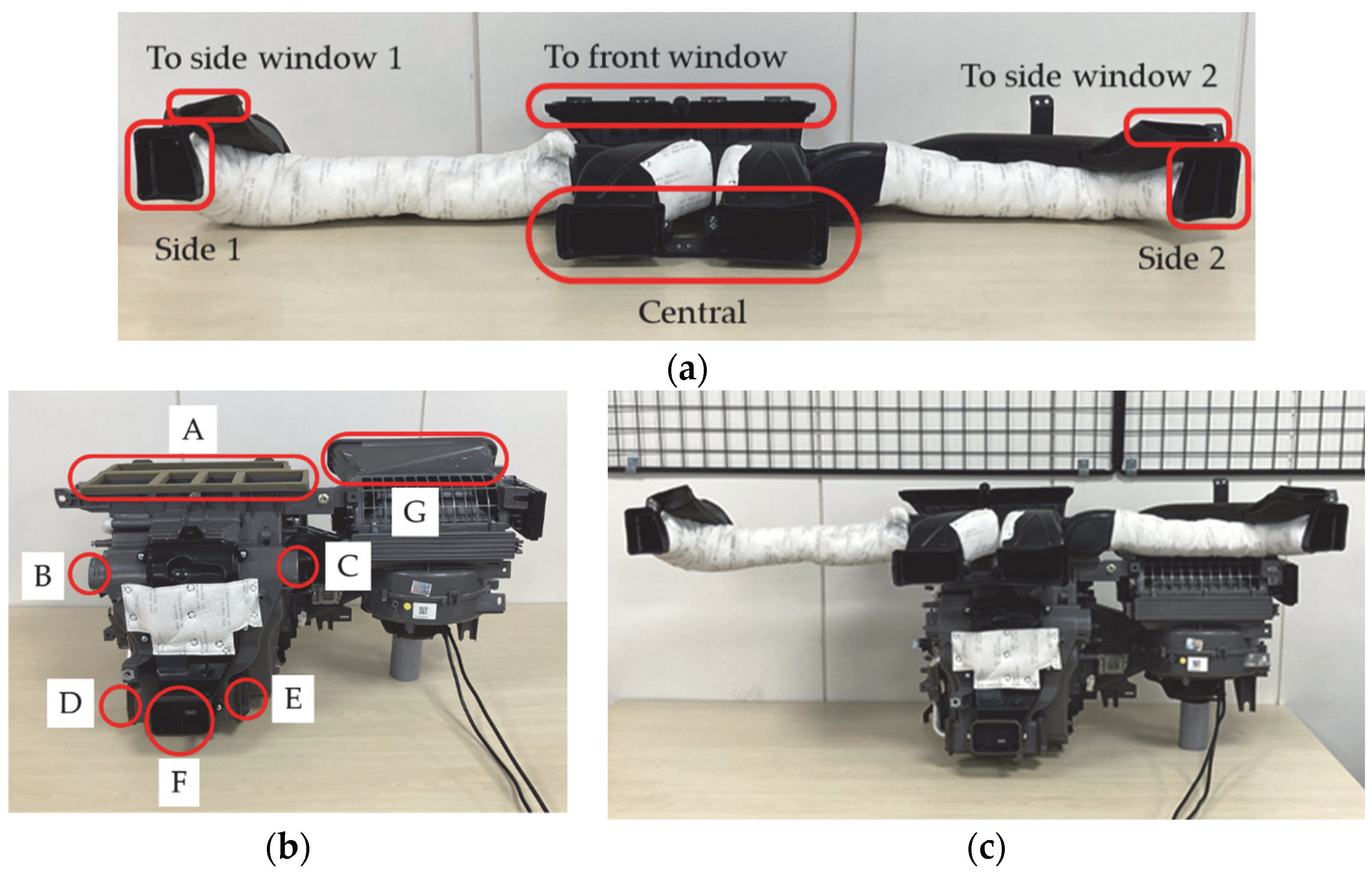
2.1. Target System
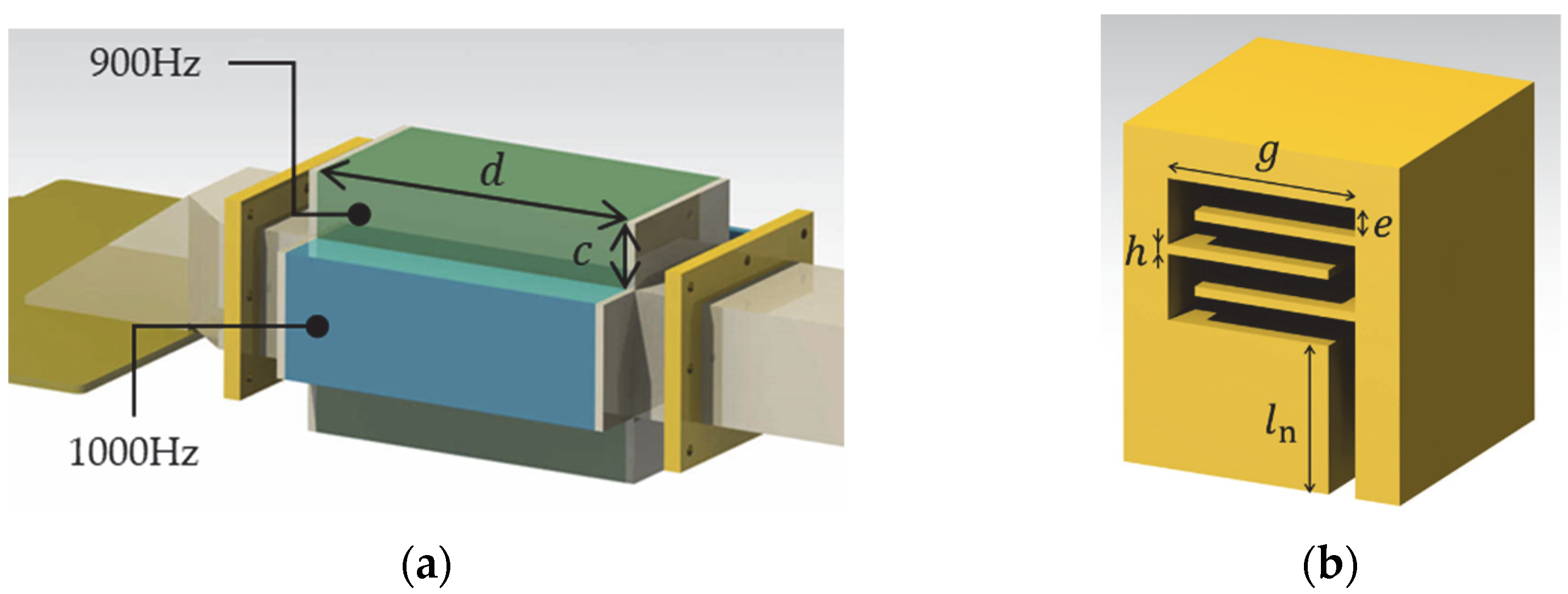
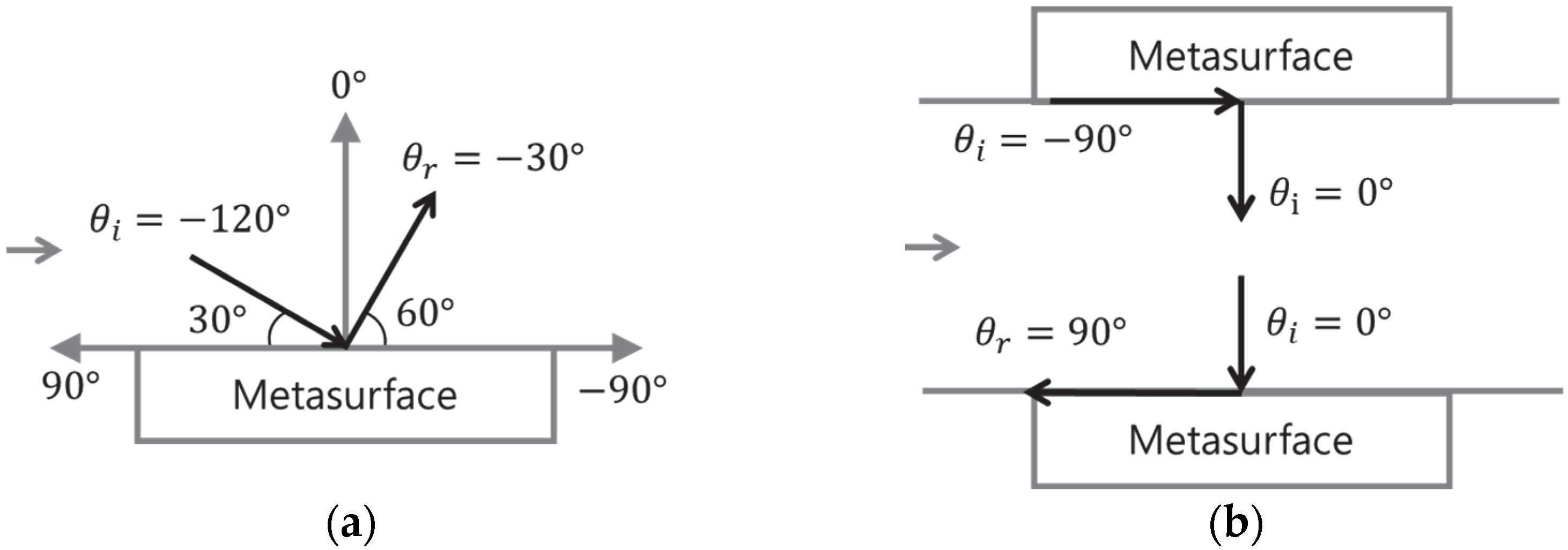
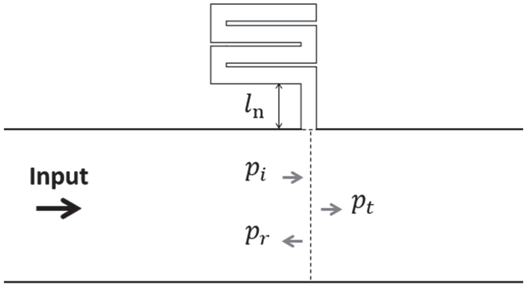
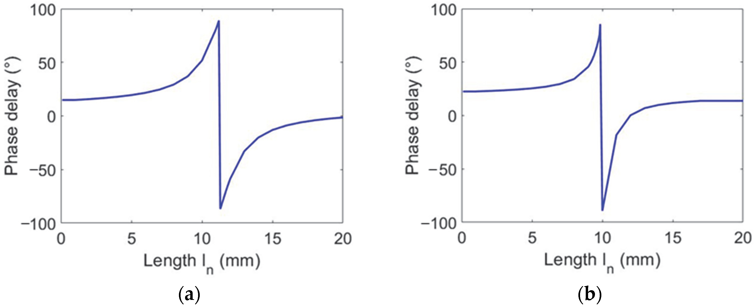
2.2. Metasilencer Design
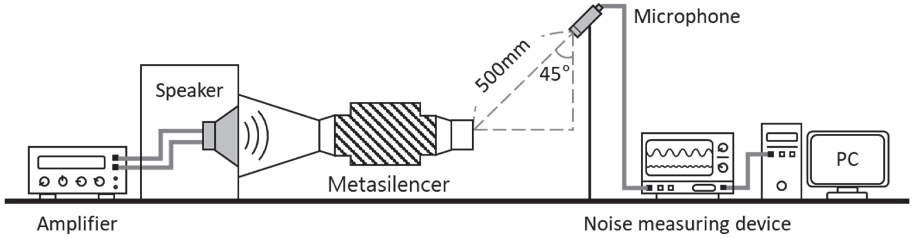
2.3. Test Setup
3. Results and Discussion
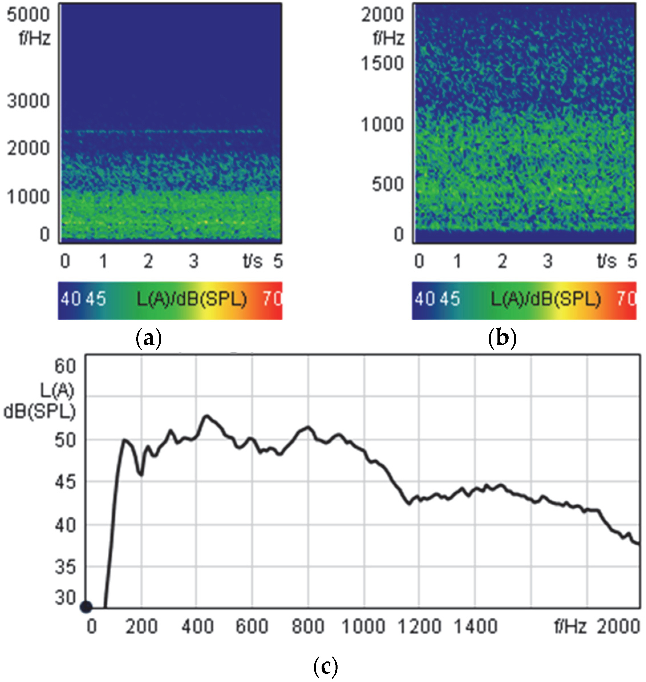
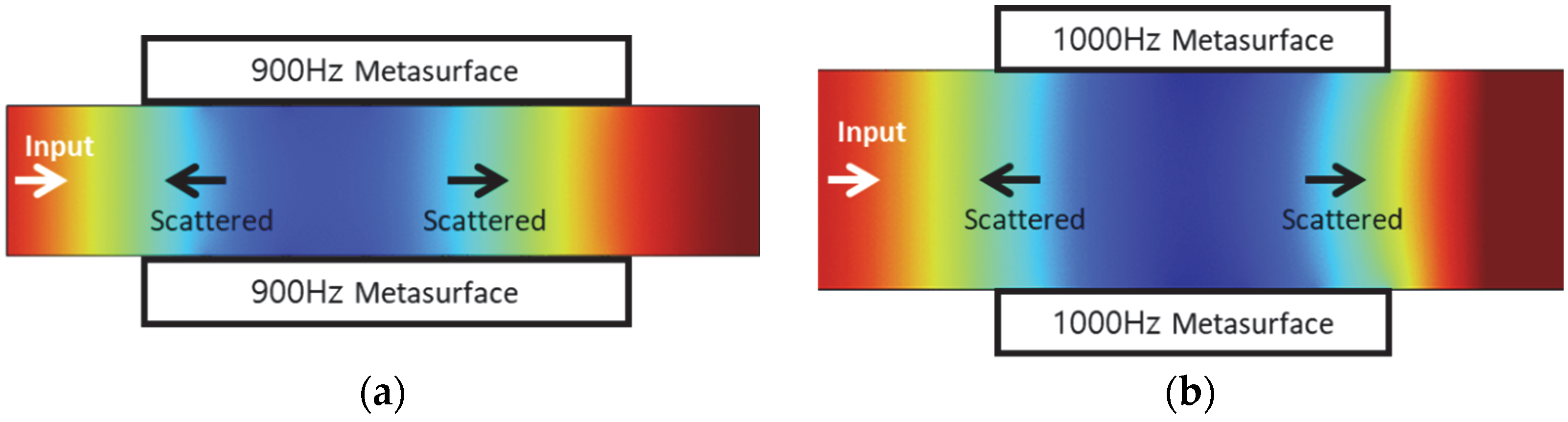
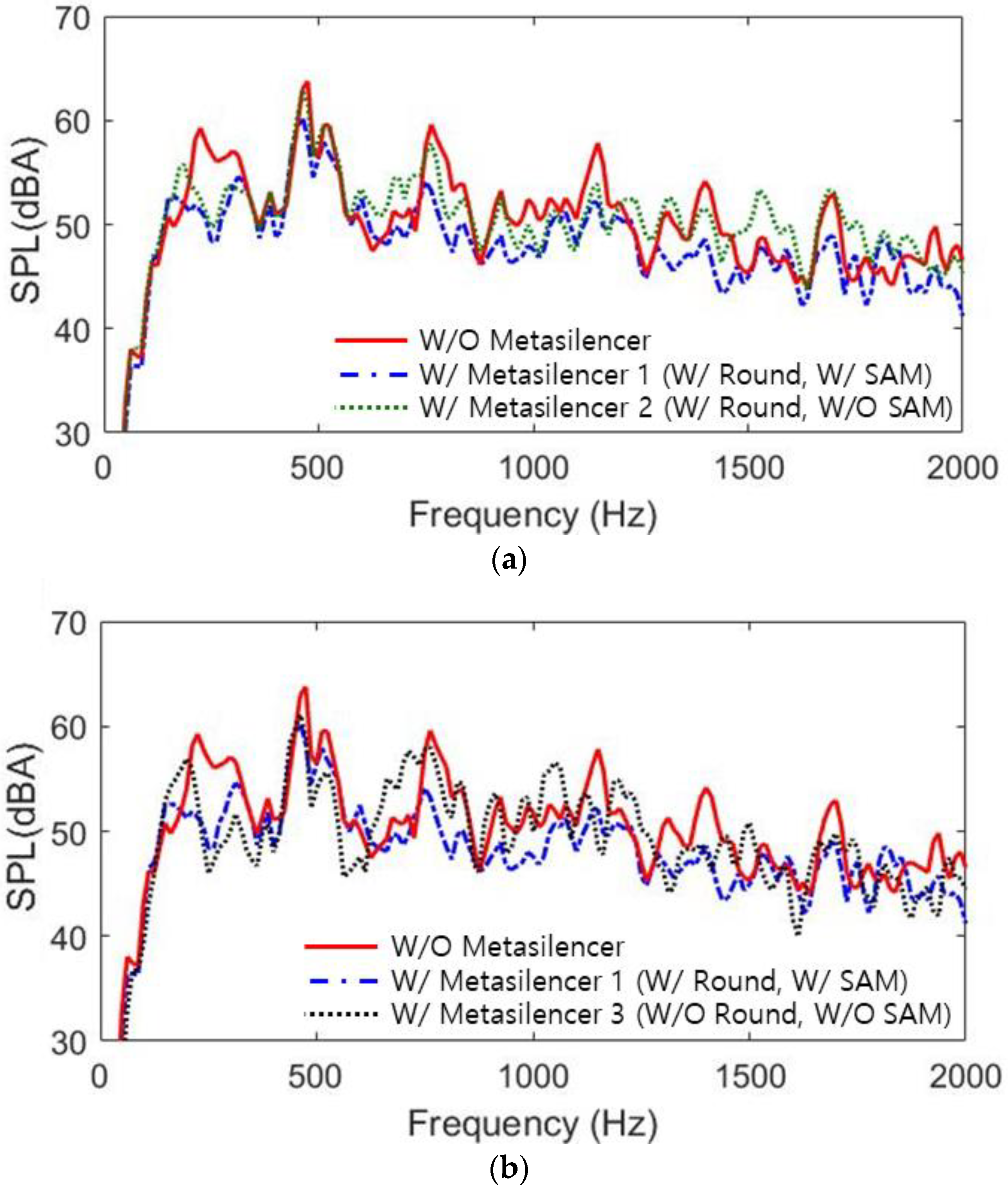
3.1. Acoustic Analysis Results
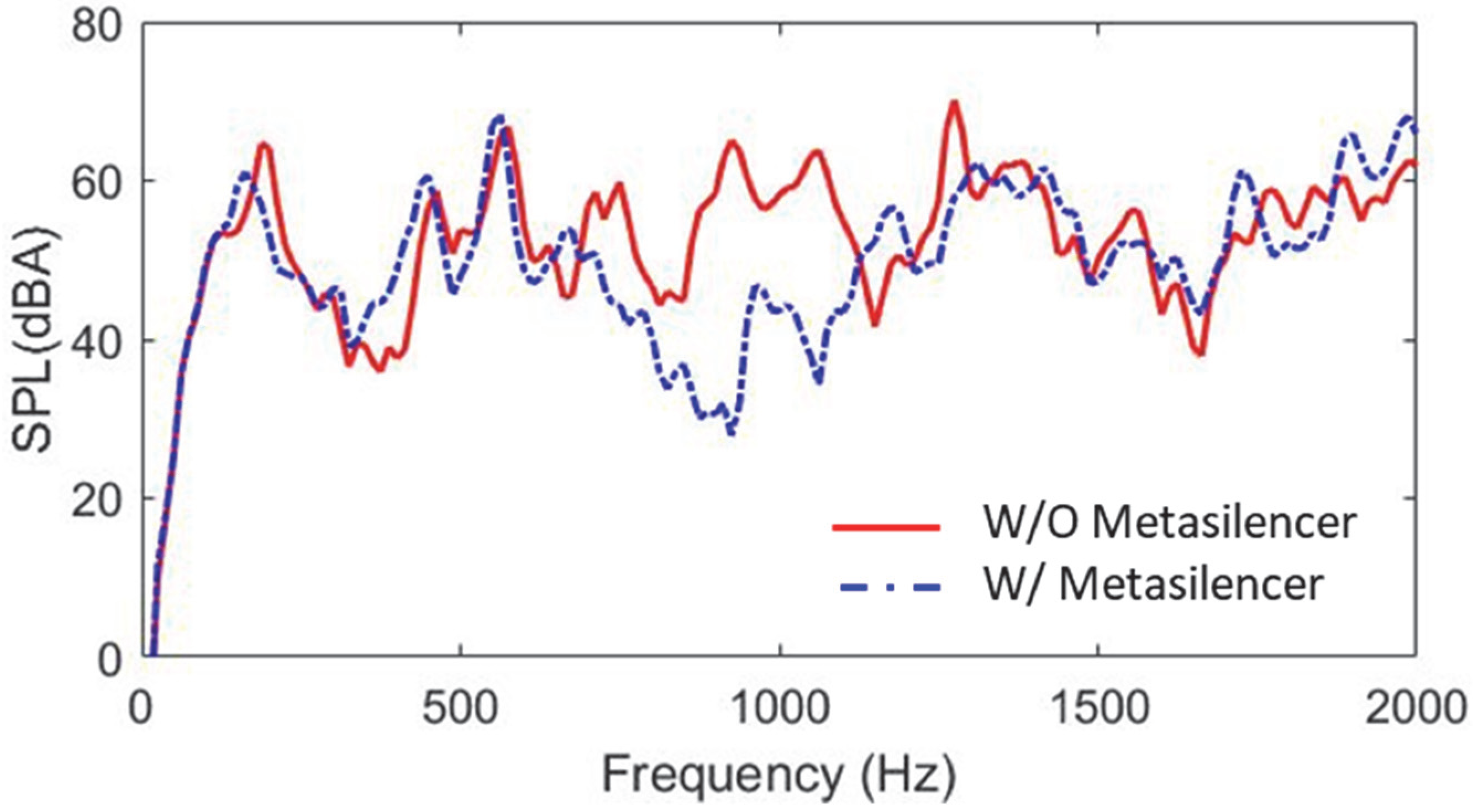
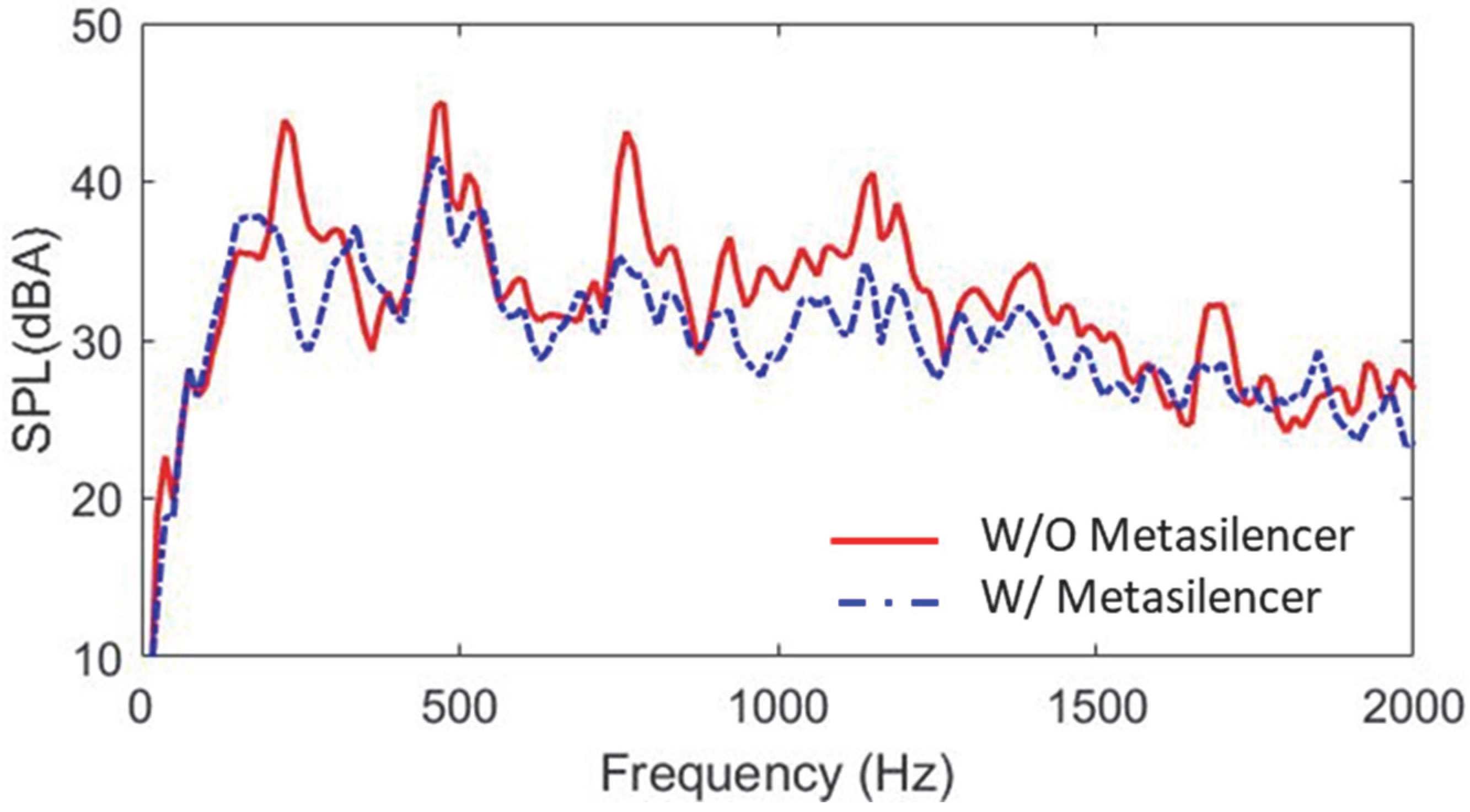
3.2. Test Results
4. Conclusions
- The target frequency of the metasilencer was selected from the acoustic measurement results of the HVAC system, and a labyrinthine-type metasilencer considering the flow noise was proposed. The metasilencer was designed using the phase delay and generalized Snell’s law.
- The inlet of the unit cell was designed as a curved structure to minimize the occurrence of turbulence at the edges of the metasilencer. In addition, a small amount of SAM was filled inside the unit cell considering the influence of the flow noise of the HVAC system.
- Acoustic analysis confirmed that the metasilencer reduced noise over a wide frequency range and that the metasurface refracts the sound propagation direction of the target frequency.
- The sound measurement results before and after installing the metasilencer in the speaker test confirmed that noise was reduced over a wide frequency range. HVAC testing confirmed the noise reduction effect of the metasilencer in the presence of flow.
Author Contributions
Funding
Conflicts of Interest
References
- Neise, W. Review of Noise Reduction Methods for Centrifugal Fans. J. Eng. Ind. 1982, 104, 151–161. [Google Scholar] [CrossRef]
- Wang, X.; Watkins, S. Noise Refinement Solutions for Vehicle HVAC Systems. SAE Trans. 2007, 116, 1620–1628. [Google Scholar] [CrossRef]
- Singh, S.; Mohanty, A.R. HVAC Noise Control Using Natural Materials to Improve Vehicle Interior Sound Quality. Appl. Acoust. 2018, 140, 100–109. [Google Scholar] [CrossRef]
- Case, J.J.; Cuddy, W.A. Application of an Acoustical Resonator to Reduce HVAC Blower Noise. SAE Tech. Pap. 2001. [Google Scholar] [CrossRef]
- Kumar, S.; Lee, H.P. The Present and Future Role of Acoustic Metamaterials for Architectural and Urban Noise Mitigations. Acoustics 2019, 1, 590–607. [Google Scholar] [CrossRef] [Green Version]
- Ge, H.; Yang, M.; Ma, C.; Lu, M.H.; Chen, Y.F.; Fang, N.; Sheng, P. Breaking the Barriers: Advances in Acoustic Functional Materials. Natl. Sci. Rev. 2018, 5, 159–182. [Google Scholar] [CrossRef]
- Kumar, S.; Lee, H.P. Recent Advances in Acoustic Metamaterials for Simultaneous Sound Attenuation and Air Ventilation Performances. Crystals 2020, 10, 686. [Google Scholar] [CrossRef]
- Chen, S.; Fan, Y.; Fu, Q.; Wu, H.; Jin, Y.; Zheng, J.; Zhang, F. A Review of Tunable Acoustic Metamaterials. Appl. Sci. 2018, 8, 1480. [Google Scholar] [CrossRef] [Green Version]
- Zangeneh-Nejad, F.; Fleury, R. Active Times for Acoustic Metamaterials. Rev. Phys. 2019, 4, 100031. [Google Scholar] [CrossRef]
- Qi, S.; Assouar, B. Ultrathin Acoustic Metasurfaces for Reflective Wave Focusing. J. Appl. Phys. 2018, 123, 234501. [Google Scholar] [CrossRef]
- Li, Y.; Jiang, X.; Liang, B.; Cheng, J.C.; Zhang, L. Metascreen-Based Acoustic Passive Phased Array. Phys. Rev. Appl. 2015, 4, 024003. [Google Scholar] [CrossRef]
- Lan, J.; Li, Y.; Xu, Y.; Liu, X. Manipulation of Acoustic Wavefront by Gradient Metasurface Based on Helmholtz Resonators. Sci. Rep. 2017, 7, 10587. [Google Scholar] [CrossRef] [PubMed] [Green Version]
- Zhu, Y.F.; Zou, X.Y.; Liang, B.; Cheng, J.C. Acoustic One-Way Open Tunnel by Using Metasurface. Appl. Phys. Lett. 2015, 107, 113501. [Google Scholar] [CrossRef]
- Liu, G.S.; Zhou, Y.; Liu, M.H.; Yuan, Y.; Zou, X.Y.; Cheng, J.C. Acoustic Waveguide with Virtual Soft Boundary Based on Metamaterials. Sci. Rep. 2020, 10, 981. [Google Scholar] [CrossRef] [PubMed] [Green Version]
- Ge, Y.; Sun, H.X.; Yuan, S.Q.; Lai, Y. Switchable Omnidirectional Acoustic Insulation through Open Window Structures with Ultrathin Metasurfaces. Phys. Rev. Mater. 2019, 3, 065203. [Google Scholar] [CrossRef]
- Ge, Y.; Sun, H.X.; Yuan, S.Q.; Lai, Y. Broadband Unidirectional and Omnidirectional Bidirectional Acoustic Insulation through an Open Window Structure with a Metasurface of Ultrathin Hooklike Meta-Atoms. Appl. Phys. Lett. 2018, 112, 243502. [Google Scholar] [CrossRef]
- Wang, W.; Xie, Y.; Konneker, A.; Popa, B.I.; Cummer, S.A. Design and Demonstration of Broadband Thin Planar Diffractive Acoustic Lenses. Appl. Phys. Lett. 2014, 105, 2012–2015. [Google Scholar] [CrossRef] [Green Version]
- Liang, Z.; Feng, T.; Lok, S.; Liu, F.; Ng, K.B.; Chan, C.H.; Wang, J.; Han, S.; Lee, S.; Li, J. Space-Coiling Metamaterials with Double Negativity and Conical Dispersion. Sci. Rep. 2013, 3, 1614. [Google Scholar] [CrossRef] [PubMed] [Green Version]
- Zhang, H.L.; Zhu, Y.F.; Liang, B.; Yang, J.; Yang, J.; Cheng, J.C. Sound Insulation in a Hollow Pipe with Subwavelength Thickness. Sci. Rep. 2017, 7, 44106. [Google Scholar] [CrossRef] [PubMed] [Green Version]
- Kim, S.J.; Huang, W.X.; Sung, H.J. The Reduction of Noise Induced by Flow over an Open Cavity. Int. J. Heat Fluid Flow 2020, 82, 108560. [Google Scholar] [CrossRef]
- Lee, I. Acoustic Characteristics of Perforated Dissipative and Hybrid Silencers; The Ohio State University: Columbus, OH, USA, 2005. [Google Scholar]


| 900 Hz | −90°/0° | 0°/90° | 30° | 31.76 mm |
| 1000 Hz | −90°/0° | 0°/90° | 30° | 28.58 mm |
| 900 Hz | 15.71 mm | 12.72 mm | 11.68 mm | 10.97 mm | 9.89 mm | 5.21 mm |
| 1000 Hz | 12.00 mm | 10.81 mm | 10.42 mm | 9.87 mm | 9.50 mm | 7.08 mm |
Publisher’s Note: MDPI stays neutral with regard to jurisdictional claims in published maps and institutional affiliations. |
© 2022 by the authors. Licensee MDPI, Basel, Switzerland. This article is an open access article distributed under the terms and conditions of the Creative Commons Attribution (CC BY) license (https://creativecommons.org/licenses/by/4.0/).
Share and Cite
Kim, H.; Kwon, Y.; Lee, S.; Kim, J.; Park, D. Development of a Metasilencer Considering Flow in HVAC Systems. Appl. Sci. 2022, 12, 11322. https://doi.org/10.3390/app122211322
Kim H, Kwon Y, Lee S, Kim J, Park D. Development of a Metasilencer Considering Flow in HVAC Systems. Applied Sciences. 2022; 12(22):11322. https://doi.org/10.3390/app122211322
Chicago/Turabian StyleKim, Hyunsu, Yoonjung Kwon, Sangwoo Lee, Juin Kim, and Dongchul Park. 2022. "Development of a Metasilencer Considering Flow in HVAC Systems" Applied Sciences 12, no. 22: 11322. https://doi.org/10.3390/app122211322