Article

1D Modeling Considering Noise and Vibration of Vehicle Window Brushed DC Motor

1
Department of Automotive Engineering, Dong-eui University, 176, Eomgwang-ro, Busanjin-gu, Busan 47340, Korea
2
Department of Mechanical Engineering, Dong-eui University, 176, Eomgwang-ro, Busanjin-gu, Busan 47340, Korea
3
R&D Division, Hyundai Motor Group, 150, Hyundaiyeonguso-ro, Namyang-eup, Hwaseong-si 18280, Gyeonggi-do, Korea
*
Author to whom correspondence should be addressed.
Appl. Sci. 2022, 12(22), 11405; https://doi.org/10.3390/app122211405
Submission received: 18 October 2022 / Revised: 4 November 2022 / Accepted: 8 November 2022 / Published: 10 November 2022

Abstract

:
This study proposes 1D modeling that considers the noise and vibration of a vehicle window-brushed DC motor. The electrical and mechanical components of the brush DC motor are included, creating a model that considers noise and vibration. The model has a back electromagnetic force (EMF) including vibration components and is constructed based on an electric circuit and transfer functions. To ensure the reliability of the model, the back EMF, noise, and vibration experiment environment of the brushed DC motor were configured. The measured back EMF was applied to the model, and it was confirmed that the simulation results of the model were consistent with the measured noise and vibrations.

1. Introduction

In recent years, the demand for electric vehicles has increased rapidly as opposed to internal combustion engine vehicles, not only with increased interest in the performance of electric vehicles but also with increasing new problems. Electric vehicles are driven by a drive motor instead of an internal combustion engine, which generates less noise than an engine does. However, in electric vehicles, a new problem of hearing subtle noises that are not audible owing to engine noise is emerging. For this reason, the problem of noise, vibration, and harshness (NVH) of a vehicle is emphasized and is an important factor in the design of vehicles.
The DC motors used in vehicles are divided into brushed DC motors and brushless DC (BLDC) motors. Brushed DC motors have the advantage of being easy to control in terms of speed and direction and are relatively inexpensive; however, there is a brush in contact with the commutator, meaning that high-speed rotation is difficult and the lifecycle of the engine is short. BLDC motors eliminate the brush and compensate for the shortcomings of DC motors, resulting in longer lifecycles and higher efficiencies. Owing to these advantages of BLDC motors, the utilization of BLDC motors is increasing, with several studies on the noise and vibration of BLDC motors currently being conducted [1,2,3,4,5]. BLDC motors, however, require additional controllers, and because of their high price compared to DC motors, traditional brushed DC motors are still widely used in many vehicles. Therefore, various studies have been conducted on the causes of noise and vibration in brushed DC motors [6,7,8,9,10]. In particular, there are research results that indicate that the electromagnetic force (EMF) generated by electromechanical machines causes noise and vibration; however, these studies did not identify the cause using modeling [11,12,13].
Several studies have been conducted to solve the noise and vibration problems in motors. For example, Finley et al. [14] and Zuo et al. [15] conducted studies to solve the motor vibration problem analytically; Jung et al. [16] and Lee et al. [17] solved the noise and vibration problem by changing the housing outside the motor, and Nakata et al. [18] studied the reduction of noise and vibration by changing the internal structure of the motor. In addition, Wang et al. [19] suggested a vibration reduction method for brushed DC motors using the sawtooth edge pole (SEP) method, and Hong et al. [20] reduced motor vibration by attaching a copper ring to the air gap of a permanent magnet. However, all of these studies dealt with methods to reduce rather than identify noise vibration components.
To develop a model for predicting the vibration component of a motor, a control model should be considered, and various studies on effective control methods have been conducted. Aung [21] modeled a DC motor using MATLAB Simulink for the effective control of wheeled mobile robots. Mapuz et al. [22] demonstrated various types of motor modeling using state space and transfer functions. Aung et al. [23] modeled a DC motor to control the motion of a robot arm, and Hwu [24] combined the functions of Powersys and Simulink to model the motor. Recently, research has been conducted using methods such as linear quadratic regulator (LQR) control [25], Fuzzy Logic (FL), and artificial neural networks (ANNs) [26]; however, these studies did not consider the noise and vibration of the DC motor. On the other hand, Kwon et al. [27] revealed that the window motor is an important part of the noise and vibration of the vehicle as it is located closest to the vehicle user and studied the method of reducing noise by analyzing the vehicle door with ANSYS structural analysis. Instead, the noise generated by the plate was reduced rather than directly reducing the noise of the motor.
This study proposes a new 1D model that can analyze noise and vibration by adding a vibration component to a brushed DC motor model. In the classic brushed DC motor model, the back EMF is simply expressed as a value proportional to the speed. However, to understand the noise and vibration of the motor analytically, the back EMF of the motor should not be proportional to a simple speed. To prove this, it was found through theory and experiments that the back EMF can be expressed as the sum of harmonics and DC. In addition, the relationship between the back EMF, noise, and vibration was shown through experiments. Finally, to create a model that can understand the vibration and noise components of the motor, this study proposes a new block diagram with the vibration component of the back EMF added, and based on the proposed block diagram, a brushed DC motor model including vibration components is created using MATLAB/Simulink.
The remainder of this paper is organized as follows. Section 2 describes the classic brush DC motor model and the formulas required to model the motor. At this time, the back electromotive, including the vibration component different from the existing model, is explained, and a block diagram to which it was applied is expressed. Section 3 describes the method to test the back EMF, noise, and vibration of the brushed DC motors. In Section 4, the experimental results are analyzed and applied to the model, whilst the simulation results are presented and discussed. Finally, Section 5 summarizes the contents of this study.

2. Modeling a Brushed DC Motor

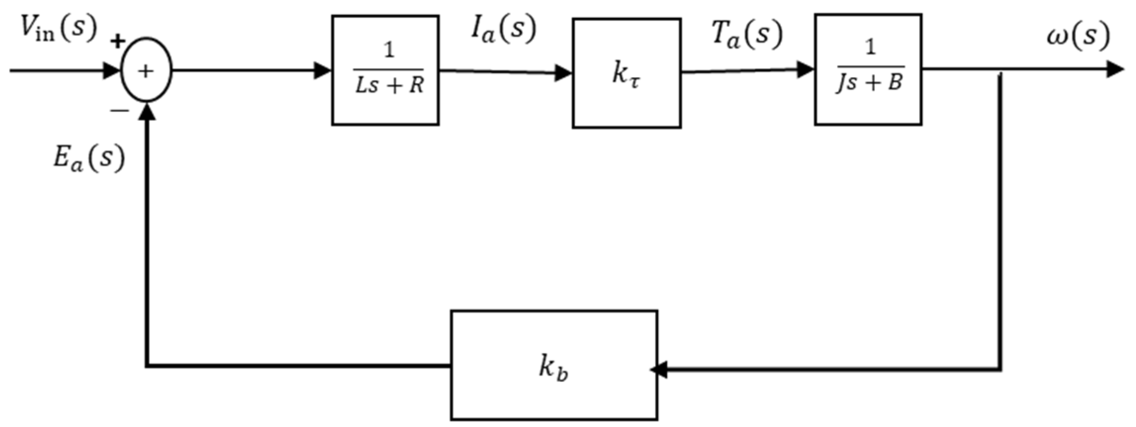
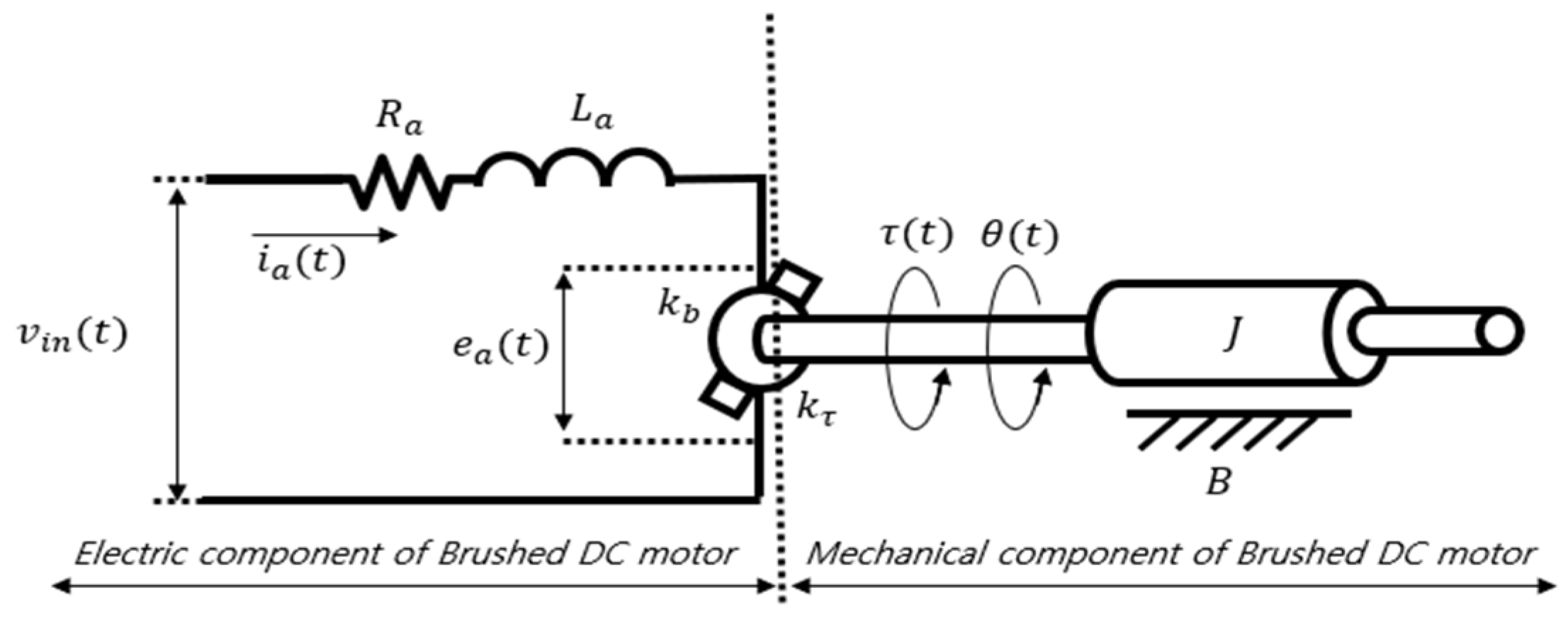
2.1. Classic Brushed DC Motor Modeling

The first step in modeling a brushed DC motor is to create an equation that includes the electrical and mechanical components of the DC motor. The denominations of the electrical and mechanical elements are listed in Table 1, and a simplified diagram containing them is shown in Figure 1.
In the brushed DC motor electrical elements shown in Figure 1, the applied voltage can be expressed as the sum of the differential equation of the current and the back EMF via Kirchhoff’s voltage law:
V i n ( t ) = R a i a ( t ) + L a d i a d t + e a ( t )  
Then, for the mechanical element shown in Figure 1, using Newton’s second law, the torque produced by the motor can be expressed as a differential equation of the angle position:
τ ( t ) = B d θ d t + J d 2 θ d t 2  
The back EMF generated by the motor is proportional to its rotational speed and can be expressed as the product of the back EMF constant k b and angular velocity ω, as expressed in Equation (3). A description of the back EMF is provided in Section 2.2.
e a ( t ) = k b ω ( t )  
The torque generated by the motor is proportional to the current flowing through the motor and can be expressed as the product of i a ( t ) and torque constant k τ :
τ ( t ) = k τ i a ( t )  
The Laplace transform can then be performed using Equations (1)–(4), and thus, a block diagram for modeling can be generated. Refer to Appendix A for a complete breakdown.

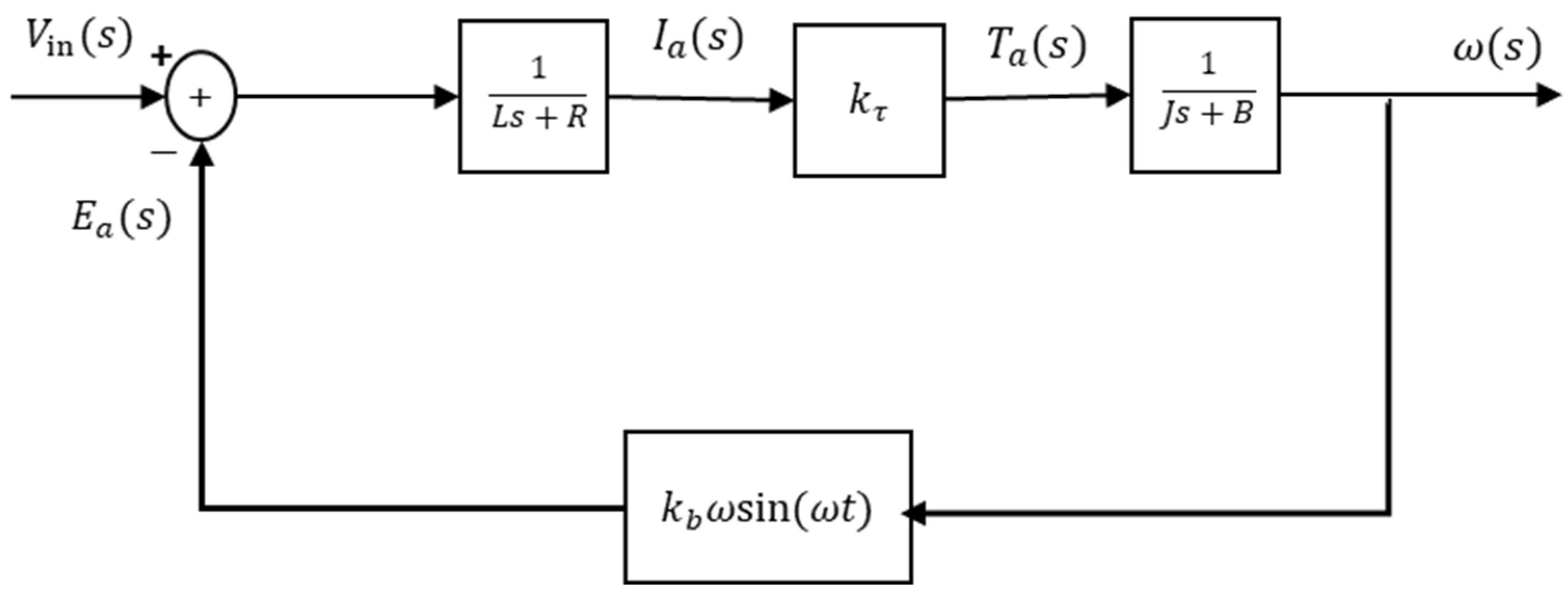
2.2. Brushed DC Motor Modeling Considering Back EMF Vibration

As previously mentioned, EMF is one of the factors that can cause noise and vibration in electrical machines. This study attempted to predict the noise and vibration using the back EMF of a brushed DC motor. The back EMF refers to the induced voltage that prevents current flow while the motor rotates, which causes voltage to be generated in the direction opposite to the voltage applied from the power source, and the voltage applied to the motor drops. The back EMF can be measured using the voltage generated by the motor when the motor rotates with no load without a power supply. Without load, the back EMF can represent the motor characteristics itself with certain DC and AC components without affecting by input current. The back EMF expressed in Equation (3) is typically modeled as a single value for simplicity but cannot be a constant in real terms. In a brushed DC motor, the stator produces a magnetic flux density B between the permanent magnets, and the rotor consists of a coil wound N times around the cross-sectional area S. In a magnetic field with uniform magnetic flux density B, the coil is wound N times based on the cross-sectional area S, and when the coil rotates at a speed of ω, a back EMF is generated, as shown below:
e a ( t ) = N B S ω s i n ( ω t )
In brushed DC motors, the cross-sectional area of the rotor and the number of turns of the coil are constant, and the magnetic flux density of the stator is also constant because it is generated by permanent magnets. Therefore, the back EMF can be summarized as Equation (6) by expressing N · B · S as a single constant k b .
e a   ( t ) = k b ω s i n ( ω t )
In other words, even when rotating at the same speed, the back EMF value changes to harmonics depending on the time t. The sinusoidal characteristics of this back EMF affect the voltage applied to the motor and therefore the current, torque, and angular velocity of the motor as well. This effect causes motor rotational vibration, which leads to motor noise. Using Equation (6), the back EMF, including the vibration component, can be expressed in a block diagram, as shown in Figure 2.

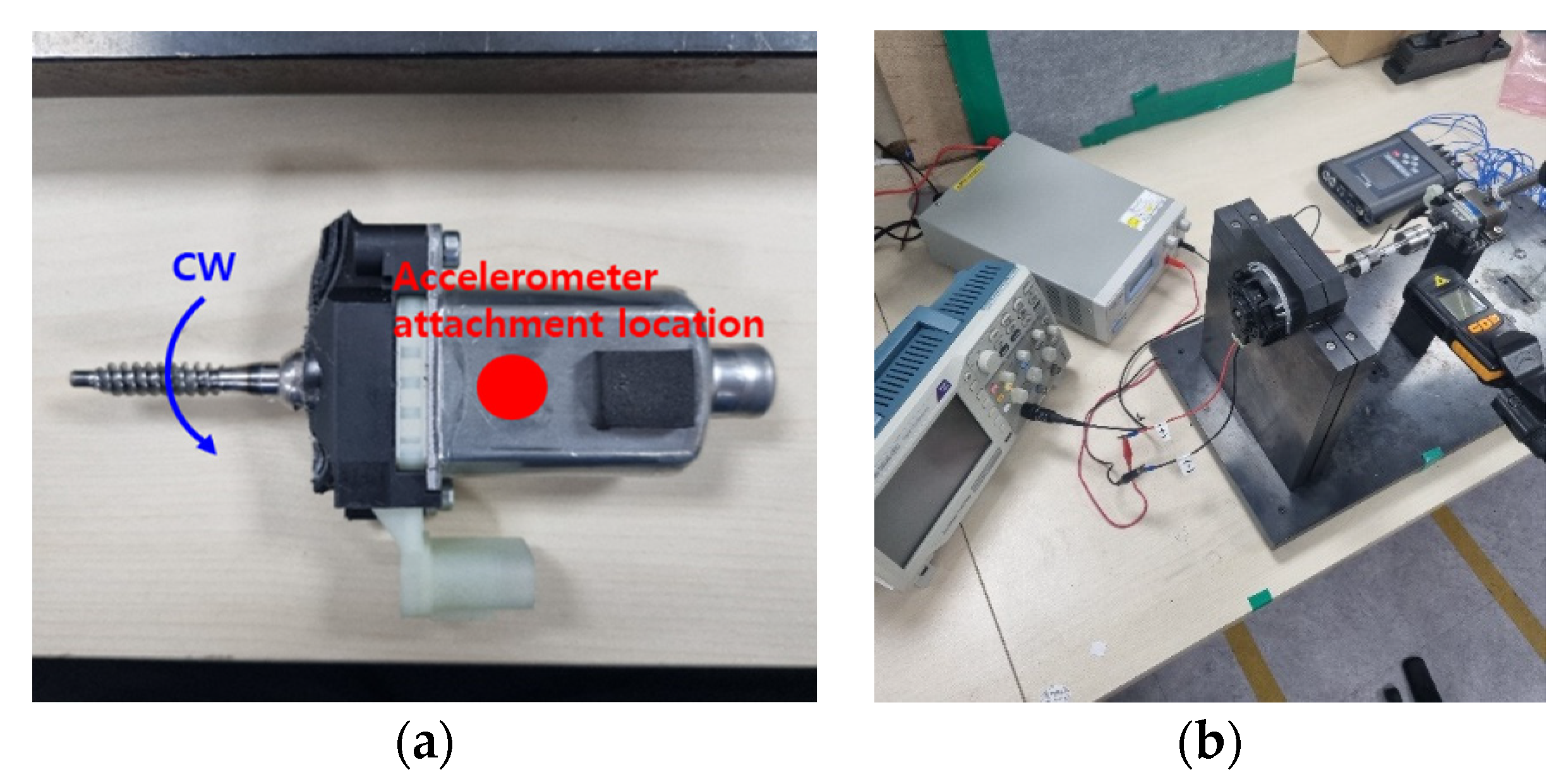
3. Experimental Setup

3.1. Considerations for Experimentation

The vehicle window brushed motor used in the experiment was a combination of a motor and a worm gear. As the motor rotates, it moves the worm gear, which affects the structure of the vehicle window. Therefore, the window of the vehicle is moved by controlling the motor. The housing of the sample motor covered the worm gear, and a power connector was coupled between the housing and the motor. To apply the back EMF, including the vibration component, to the model, the noise and vibration of the sample motor are measured in Section 3.2, and the back EMF is measured in Section 3.3.

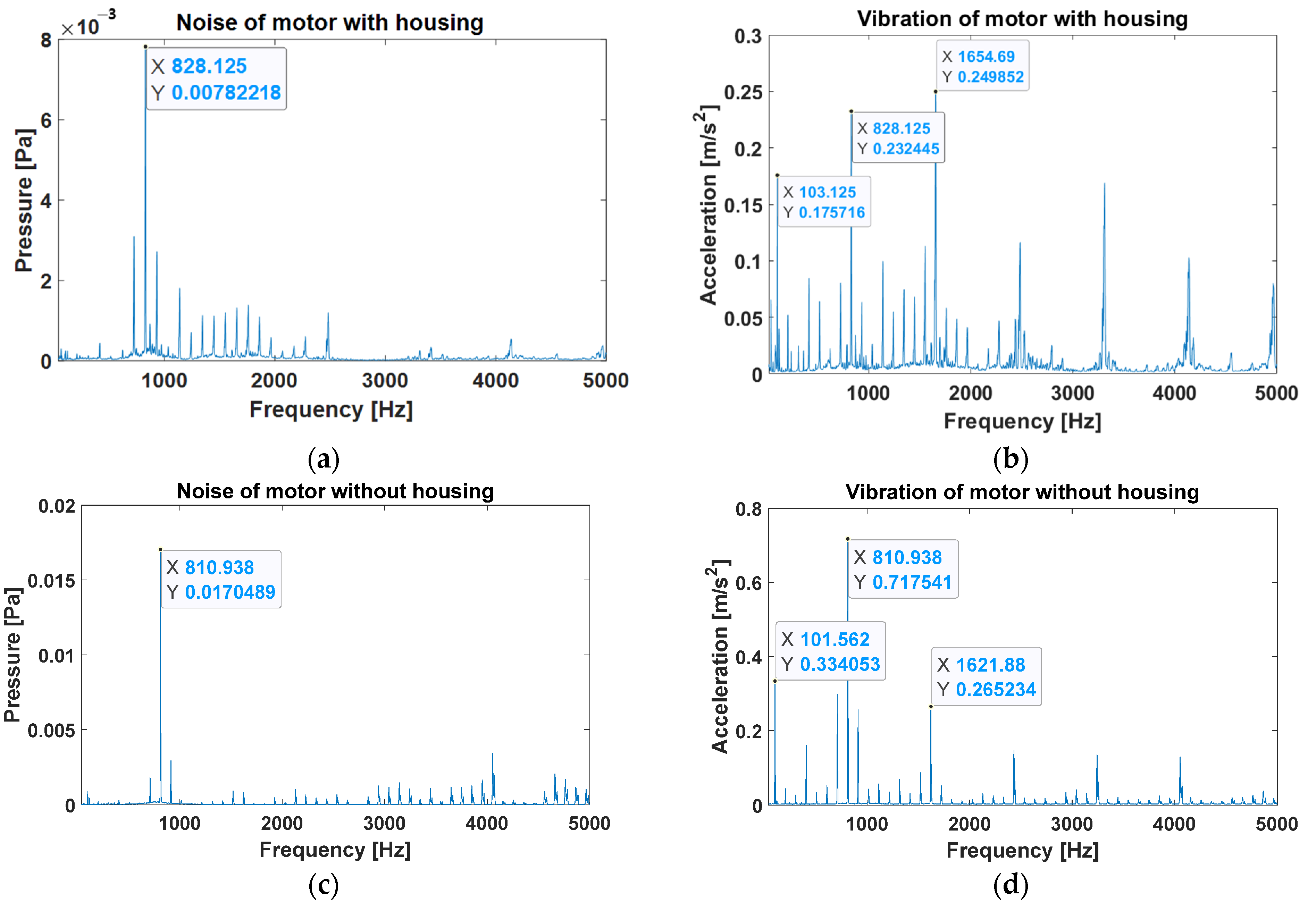
3.2. Noise and Vibration Measurement of Motor with Housing

The vehicle window motor used in the experiment was a 2-pole 8-slot brushed DC motor that rotates at 6200 RPM from a rated voltage of 12 V (Figure 3a). In the noise and vibration measurement experiment, 12 V power was supplied to the test motor using a power source. The test motor was driven in a no-load state and was performed on bubble wrap as a test environment similar to the free-boundary condition (Figure 3b). At this time, the reason for testing noise and vibration at no load is that the back EMF value to be measured is carried out at no load. An HT356A02 accelerometer (PCB Piezotronics) was mounted on top of the test motor to measure the vibration and a 378B02 microphone from PCB Piezotronics was installed at an angle of 45° to measure the noise component. At this time, to obtain a sufficient SPL (Sound Pressure Level) value to analyze the noise component, a microphone was installed at a distance of 15 cm from the motor rotating part to obtain a sufficient SPL value to analyze the noise component. Head Acoustics Squadriga II was used as the measuring instrument, and the measured data were processed using MATLAB.

3.3. Back EMF and Noise and Vibration Measurement of Motor without Housing

To measure the back EMF, the housing of the test motor was removed (Figure 4a) and an experimental setup that could connect the driving motor to the test motor was constructed (Figure 4b). The drive motor and sample motor were connected using a shaft and two couplings, and the experiment was conducted in such a way that the test motor rotated when power was applied to the drive motor. An oscilloscope was connected to the power connector of the motor to measure the back EMF, and the speed was measured using a Benetech’s GM8905 tachometer, which is capable of measuring noncontact to maintain the motor speed constant. Noise and vibration measurements and data processing were performed in the same manner as described in Section 3.2.

4. Experiment Results and Discussion

4.1. Noise and Vibration Experiment

The experimental results obtained with and without the housing of the test motor are shown in Figure 5. Given that the test motor is a 2-pole 8-slot motor, the eighth-order component, which is the least common multiple of the number of poles and slots, is the primary rotational vibration component [6]. As shown in Figure 5, the eighth-order component and its harmonic components due to motor rotation have the greatest impact on noise and vibration. In other words, the eighth-order and its harmonics caused by motor rotation are more dominant than the other components, most likely generated by the housing. In addition, it can be seen that the magnitude of noise and vibration varies depending on the presence or absence of the housing, which appears to be different regarding the magnitude due to the overall boundary conditions, such as motor stiffness and change. Given that the rotation speed of the motor is changed by the worm gear in the housing, the frequency of the vibration may also change slightly. However, there is no difficulty in understanding overall noise and vibration trends. Therefore, it can be seen that there is no problem, even if the noise and vibration components are analyzed using the back EMF value measured with the housing removed.
On the other hand, even if the same voltage is applied to the sample motor, the RPM of the sample motor changes, and it can be confirmed that the frequency components and magnitude of the noise and vibration in the CW (clockwise) and CCW (counterclockwise) change (Figure 6). Based on these results, it was hypothesized that the back EMF of CW and CCW would be different even if the sample motor was rotated at the same voltage. To analyze the reason, the eighth order of the motor was fixed by rotating the motor at the same RPM, and a comparison of the magnitude of the back EMF is presented in Section 4.2.

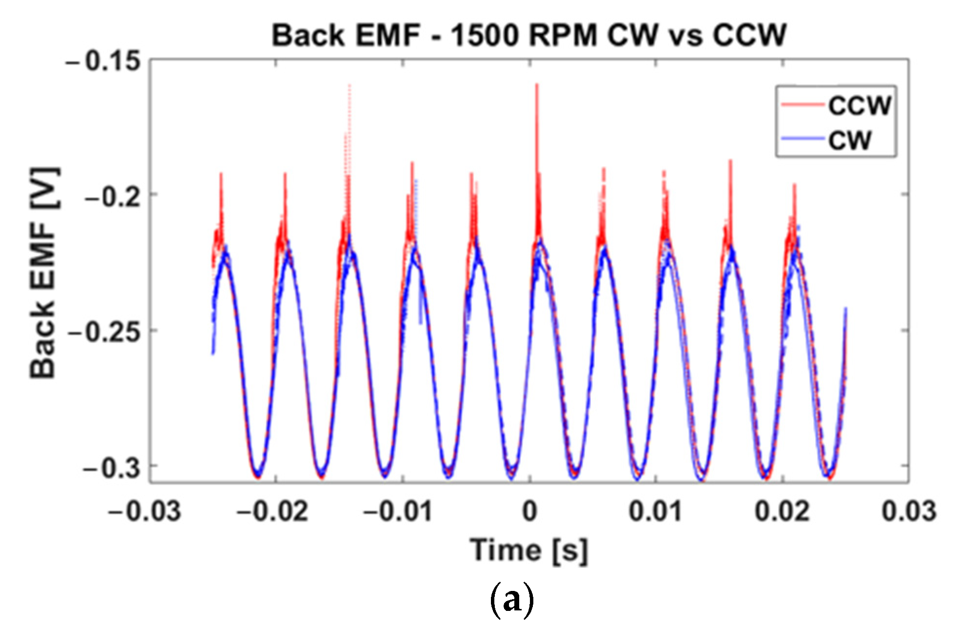
4.2. Back EMF Measurement Experiment

To confirm the back EMF component of the motor, the back EMF time data measured in the CW and CCW directions at 1500 RPM are shown in Figure 7a. In the given graph, the back EMF is not shown as a constant but appears as a sinusoidal wave that changes with time. In addition, if Equation (3) in Section 2.1 is applied at the same RPM, the back EMF should always be the same for CW and CCW, but the actual measurement results differed.
To accurately measure the back EMF according to the RPM, each RPM was measured three times from 1500 RPM to 3500 RPM, and the components of the back EMF were analyzed using FFT. Based on the back EMF FFT result, the magnitude of the eighth-order component, which is the main rotational vibration component, is shown in Figure 7b, and the magnitude of the DC component is shown in Figure 7c. Theoretically, the rotational speed of the motor at 1500 RPM is 25 [rev/s], and the eighth-order value is 200 [rev/s]. The first point in Figure 7b, which is the experimental result, was 200 [Hz]. It can be seen that the vibration frequencies of the back EMF and motor are the same. Similarly, it can be seen from Figure 7b that the eighth-order component is represented as the main vibration component for all 2000–3500 RPM. This indicates that both the CW and CCW vibration components of the back EMF coincide with the noise vibration components of the motor and that the back EMF value is not constant by ω, but by sinusoidal components that change with time. In addition, as the RPM increased, the magnitudes of both the DC component and the eighth-order component of the back EMF tended to increase.
In addition, even at the same RPM, the magnitudes of the eighth-order component of CW and CCW were different, as were the DC component. In Figure 7b, it can be seen that the magnitude of the eighth-order component is that CCW is larger than CW, which makes it possible to see that the rotational vibration of the motor is larger in CCW. As shown in Figure 7c, the magnitude of the DC component is slightly larger than that of CW. However, compared to the eighth-order component, the magnitude of the DC component is overwhelmingly 10 times larger. This difference in the DC components causes a difference in the voltage applied to the motor, which in turn affects the rotation speed of the motor. Therefore, even if the same voltage is applied, the CW rotates more slowly than the CCW, and the frequency of the rotation component is lower. Based on these results, compared with Figure 6b in Section 4.1, it can be seen that the frequency of the rotational vibration is lower in CW than in CCW, and the magnitude is smaller. On the other hand, the eighth-order component of Figure 6b and its harmonic component can be expressed in a gradually decreasing form. However, in the CCW of Figure 6a, it increased and then decreased in the range of 1500 Hz to 5000 Hz. Judging from the results of Figure 7a, these peaks appear to be caused by sparks between the brush contacts, and it is expected that CW and CCW will differ depending on the wear condition of the brush. Sparking noises do not significantly affect vibration but seem to affect noise. Further research will need to be conducted to clarify this.
Based on this result, the back EMF function was created using the magnitude of the eighth-order component and DC components. The sinusoidal back EMF function derived in this manner was applied to the model, and the results are explained in Section 4.3.

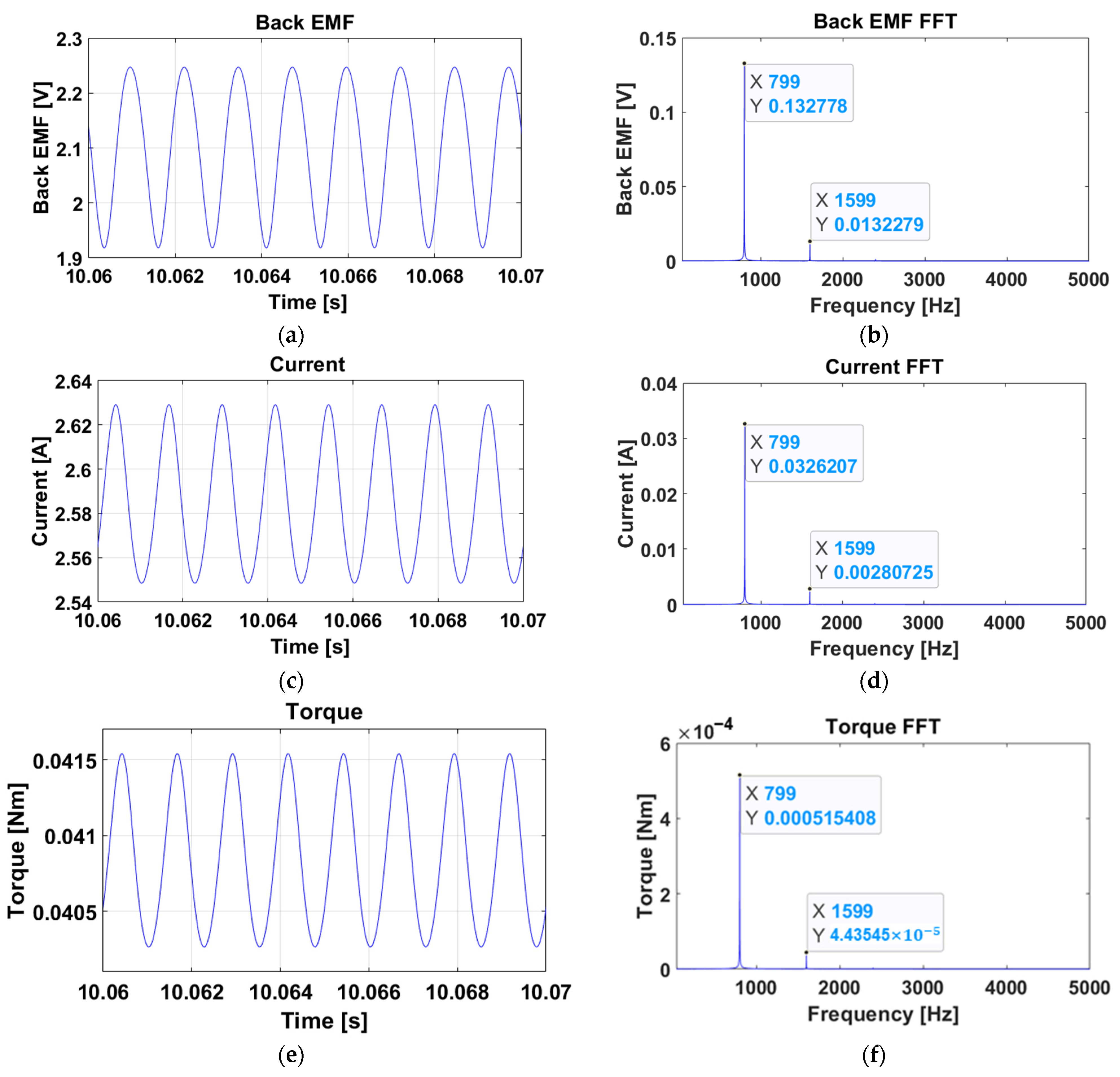
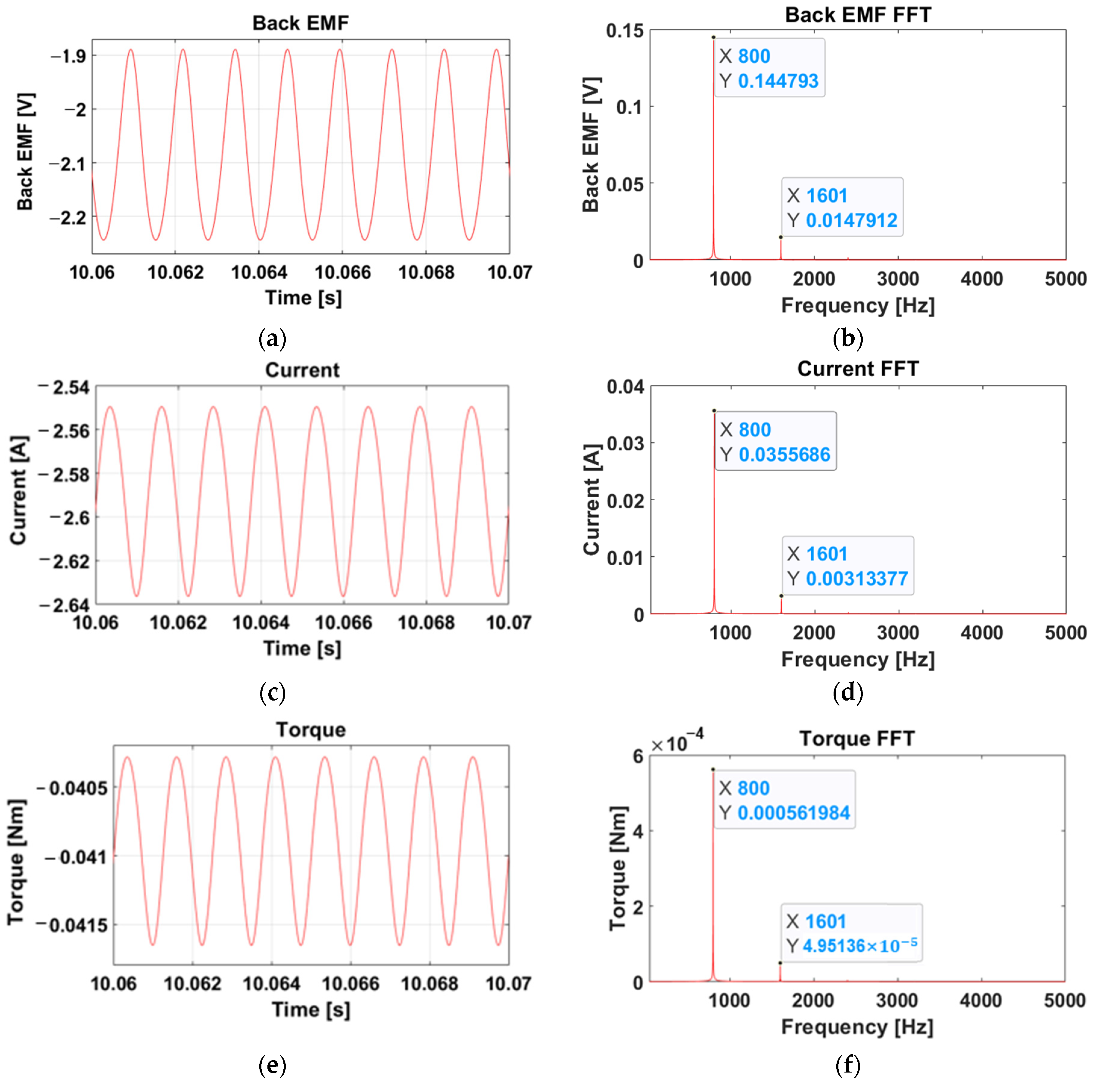
4.3. Model and Simulation Results with Vibration Components

Based on the block diagram (Figure 2) presented in Section 2.2, a model was created using MATLAB Simulink (Figure 8). The electrical elements are expressed as circuit models, and mechanical elements are expressed as transfer-function models. Here, “fcn” is a block for expressing back EMF and is a new part that is not in the general model. To obtain a similar RPM to that of the sample motor in the model, arbitrary values were input to each parameter so that it could rotate at 6000 RPM at a rated 12 V, and the values are shown in Table 2. Back EMF measurement was only possible up to 3500 RPM owing to the limitations of the drive motor; however, in the results of Figure 7b,c, the magnitude and frequency have a constant tendency, meaning that they can be applied, even at 6000 RPM. The frequency of the back EMF function was designed to have an eighth-order component, which is a motor rotational vibration component. The back EMF of CW and CCW is expressed by Equations (7)–(9) and (10)–(12), and applied to the “fcn” block.
k b = ( 0.2056 × 8 f + 0.0932 × 10 3 ) × 10 3
D C = 0.0207 f + 0.0117
E a = k b sin ( 8 ω t ) + D C
k b = ( 0.2212 × 8 f 0.0315 × 10 3 ) × 10 3
D C = 0.0205 f 0.0125
E a = k b sin ( 8 ω t ) + D C
The simulation results for the CW and CCW are shown in Figure 9 and Figure 10. The eighth-order frequency component applied to the model was confirmed in the back EMF, current, and torque. In addition, as shown in Figure 6b of Section 4.1, the vibration test results show that the frequency of the vibration component of CCW was higher than that of CW, even when the same voltage was input, whilst the magnitude was also larger. The same voltage was input in the simulation as well, and it was confirmed that the frequency of CCW was higher than that of CW, and the magnitude was also larger (Figure 9b, Figure 10b). Table 3 summarizes the contents of this study. It can be seen that these characteristics appear the same in current (Figure 9d, Figure 10d) and torque (Figure 9f, Figure 10f). In addition, the harmonic of the vibration component was also confirmed in the simulation, and it can be observed that it has the same characteristics as a real motor.
On the other hand, comparing the measurement results in Figure 7a with the simulation results in Figure 9b and Figure 10b, the simulation result waveform is drawn in a much cleaner form. This is because only the eighth-order vibration among the vibration components of the motor was considered. If vibration components other than eighth-order vibration are considered and applied to the model, simulation results more similar to actual measurements can be obtained. However, considering the eighth-order vibration, which has the greatest influence among the vibration elements of the motor, is a sufficiently significant result for predicting the vibration.
This model can be used in various applications. For example, in the power connection part of a brushed DC motor, there are several electrical elements for noise removal and motor protection, which can be expressed as a circuit in the model to predict the change in vibration caused by this. In addition, it is expected that it can be used as a filter for vibration reduction by combining various electronic elements such as resistors, inductors, and capacitors based on the predicted vibration component and adding it between the power connection part and the motor. Even when the motor operates with a load, the vibration component of the motor, including the load, can be predicted by applying the load to the model. This has a significant advantage over other models that have been previously studied.

5. Conclusions

To model the motor considering noise and vibration, the motor was modeled by adding the back EMF, including the vibration component, to the equations and block diagrams of the classic motor model. To model the vibration component of the back EMF, the back EMF of the test motor was measured with an oscilloscope. Based on these results, a back EMF function was generated using the eighth-order component and DC components. A simulation was performed based on the model to which the vibration component was added, and it was found that the result was the same as that of the measured component. The conclusions of this study are as follows:
  • To create a model expressing noise and vibration from the traditional motor equation, it was confirmed that the back EMF is composed of the sum of harmonic and DC components rather than constants and is expressed as a block diagram based on the equation.
  • The back EMF value was measured using an actual motor, and experiment results confirmed that the vibration components of the motor and back EMF tended to be identical. However, it was confirmed that CW and CCW, which should theoretically be the same, are different in actual motors. This was attributed to the difference between the DC component and the eighth-order component of the back EMF. However, further research on the harmonic components observed in the noise component of the CCW should be conducted.
  • The entire model was constructed based on the block diagram, and it was modeled using MATLAB Simulink based on the electric circuit and transfer function. To verify the reliability of the model, the measured back EMF value was applied to the model, and it was confirmed that the predicted vibration component was consistent with the actual vibration component. This will be of great help in predicting the main vibration component in a brushed DC motor. Given that it does not include all vibration components, it can be expressed in a simpler form than the actual measurement result; however, it is still successful as it predicts the largest vibration component.
  • The brushed DC motor model created in this study to predict the vibration component of the motor can be applied in various fields. For example, if R, L, and C are attached to the tip of the motor resistor and inductor and used as a filter, they can be applied to reduce noise and vibration. Alternatively, the vibration component generated by the motor can be predicted when a specific load is applied.

Author Contributions

Methodology, D.W.; Project administration, H.K.; Software, J.K. and K.H.; Writing—review & editing, H.K. All authors have read and agreed to the published version of the manuscript.

Funding

This research was supported by Hyundai Motor’s industry–academic research project. This research was supported by the MSIT (Ministry of Science and ICT), Korea, under the Grand Information Technology Research Center support program (IITP-202-2020-0-01791) supervised by the IITP (Institute for Information & Communications Technology Planning & Evaluation). This work was supported by the National Research Foundation of Korea (NRF) grant funded by the Korea government (MSIT) (No. NRF-2021R1F1A1062389).

Conflicts of Interest

The authors declare no conflict of interest.

Appendix A

Using the Laplace transform, Equations (A1)–(A4) can be transformed into the Laplace domain as follows:
V i n ( s ) = R a I a ( s ) + s L a I a ( s ) + E a ( s )
Τ ( s ) = s B Θ ( s ) + s 2 J Θ   ( s )
E a ( s ) = k b ω ( s )
Τ ( s ) = k τ I a ( s )
For modeling, if Equation (A1) is rearranged as an expression for I a ( s ) :
I a ( s ) = 1 L a s + R a ( V i n ( s ) E a ( s ) )
To derive the relation between the angle Θ(s) and the torque Τ(s), Equation (A2) can be rearranged as an expression for Θ(s):
Θ ( s ) = 1 J s 2 + B s · Τ ( s )
Given that the angular velocity ω ( s ) is the derivative of the angle Θ ( s ) with respect to time t, Equation (A6) can be written as follows:
ω ( s ) = s Θ ( s ) = 1 J s + B · T ( s )
It can be expressed as a block diagram using Equations (A3)–(A6), as shown in Figure A1.
Figure A1. Classic block diagram of brushed DC motor.
Applsci 12 11405 g0a1

References

  1. Pindoriya, R.M.; Mishra, A.K.; Rajpurohit, B.S.; Kumar, R. An Analysis of Vibration and Acoustic Noise of BLDC Motor Drive. In Proceedings of the 2018 IEEE Power & Energy Society General Meeting (PESGM), Porland, OR, USA, 5–10 August 2018. [Google Scholar]
  2. Kang, G.H.; Son, Y.D.; Kim, G.T. The Noise and Vibration Analysis of BLDC Motor Due to Asymmetrical Permanent-Magnet Overhang Effects. IEEE Trans. Ind. Appl. 2008, 44, 1569–1577. [Google Scholar] [CrossRef]
  3. Hur, J.; Reu, J.W.; Kim, B.W.; Kang, G.H. Vibration Reduction of IPM-Type BLDC Motor Using Negative Third Harmonic Elimination Method of Air-Gap Flux Density. IEEE Trans. Ind. Appl. 2011, 47, 1300–1309. [Google Scholar]
  4. Jafarboland, M.; Farahabadi, H.B. Optimum Design of the Stator Parameters for Noise and Vibration Reduction in BLDC Motor. IET Electr. Power Appl. 2018, 12, 1297–1305. [Google Scholar] [CrossRef]
  5. Shifat, T.A.; Hur, J.W. An Effective Stator Fault Diagnosis Framework of BLDC Motor Based on Vibration and Current Signals. IEEE Access 2020, 8, 106968–106981. [Google Scholar] [CrossRef]
  6. Cho, Y.T. Characterizing Sources of Small DC Motor Noise and Vibration. Micromachines 2018, 9, 84. [Google Scholar] [CrossRef] [Green Version]
  7. Kang, H. The Study of DC Motor Noise and Vibration. SAE Trans. 1995, 104, 2461–2467. [Google Scholar]
  8. Iorgulescu, M.; Beloiu, R. Study of DC Motor Diagnosis Based on the Vibration Spectrum and Current Analysis. In Proceedings of the 2012 International Conference on Applied and Theoretical Electricity (ICATE), Craiova, Romania, 25–27 October 2012. [Google Scholar]
  9. Cho, Y.T. Noise Source Visualization for Small DC Motors Using Current Reference without a Reference Microphone. Micromachines 2018, 9, 290. [Google Scholar] [CrossRef] [Green Version]
  10. Wang, S.; Hong, J.; Sun, Y.; Cao, H. Analysis and Reduction of Electromagnetic Vibration of PM Brush DC Motors. IEEE Trans. Ind. Appl. 2019, 55, 4605–4612. [Google Scholar] [CrossRef]
  11. Michaelides, A.; Pollock, C. Reduction of Noise and Vibration in Switched Reluctance Motors: New Aspects. In Proceedings of the Conference Record of the 1996 IEEE Industry Applications Conference Thirty-First IAS Annual Meeting (IAS ’96), San Diego, CA, USA, 6–10 October 1996; Volume 2, pp. 771–778. [Google Scholar]
  12. Verma, S.P.; Balan, A. Experimental Investigations on the Stators of Electrical Machines in Relation to Vibration and Noise Problems. IEE Proc. Electr. Power Appl. 1998, 145, 455–461. [Google Scholar] [CrossRef]
  13. Lee, C.I.; Jang, G.H. Noninvasive Detection of Unevenly Magnetized Permanent Magnet of a Brushless Dc Motor by Characterizing Back Electromotive Force. J. Appl. Phys. 2009, 105, 105–108. [Google Scholar] [CrossRef]
  14. Finley, W.R.; Hodowanec, M.M.; Holter, W.G. An Analytical Approach to Solving Motor Vibration Problems. In Proceedings of the Industry Applications Society 46th Annual Petroleum and Chemical Technical Conference (Cat. No. 99CH37000), San Diego, CA, USA, 13–15 September 1999. [Google Scholar]
  15. Zuo, S.; Lin, F.; Wu, X. Noise Analysis, Calculation, and Reduction of External Rotor Permanent-Magnet Synchronous Motor. IEEE Trans. Ind. Electron. 2015, 62, 6204–6212. [Google Scholar] [CrossRef]
  16. Jung, I.; Yang, H.; Park, T.; Kim, J. A Study on Noise Reduction of a DC Motor. KSNVE 2004, 5, 764–769. [Google Scholar] [CrossRef]
  17. Lee, S.H.; Hong, J.P.; Hwang, S.M.; Lee, W.T.; Lee, J.Y.; Kim, Y.K. Optimal Design for Noise Reduction in Interior Permanent-Magnet Motor. IEEE Trans. Ind. Appl. 2009, 45, 1954–1960. [Google Scholar]
  18. Nakata, K.; Hiramoto, K.; Sanada, M.; Morimoto, S.; Takeda, Y.; Yamai, H. Noise Reduction for Switched Reluctance Motor with a Hole. In Proceedings of the Proceedings of the Power Conversion Conference-Osaka 2002 (Cat. No. 02TH8579), Osaka, Japan, 2–5 April 2002. [Google Scholar]
  19. Wang, S.; Yang, Z.; Liu, C. Vibration Reduction Characteristics of Permanent Magnet DC Motors with Sawtooth Edge Poles. IEEE Trans. Energy Convers. 2021, 36, 737–745. [Google Scholar] [CrossRef]
  20. Hong, J.; Wang, S.; Sun, Y.; Cao, H. An Effective Method with Copper Ring for Vibration Reduction in Permanent Magnet Brush DC Motors. IEEE Trans. Magn. 2018, 54, 1–5. [Google Scholar] [CrossRef]
  21. Aung, W.P. Analysis on Modeling and Simulink of DC Motor and Its Driving System Used for Wheeled Mobile Robot. World Acad. Sci. Eng. Technol. 2007, 32, 299–306. [Google Scholar]
  22. Mahfouz, A.A.; Mohammed, M.K.; Salem, F.A. Modeling, Simulation and Dynamics Analysis Issues of Electric Motor, for Mechatronics Applications, Using Different Approaches and Verification by MATLAB/Simulink. Int. J. Intell. Syst. Appl. 2013, 5, 39–57. [Google Scholar] [CrossRef] [Green Version]
  23. Aung, C.H.; Lwin, K.T.; Myint, Y.M. Modeling Motion Control System for Motorized Robot Arm Using MATLAB. Eng. Technol. 2008, 42, 372–375. [Google Scholar]
  24. Hwu, K.I. Applying POWERSYS and SIMULINK to Modeling Switched Reluctance Motor. Tamkang J. Sci. Eng. 2009, 12, 429–438. [Google Scholar]
  25. Chotai, J.; Narwekar, K. Modelling and Position Control of Brushed DC Motor. In Proceedings of the 2017 International Conference on Advances in Computing, Communication and Control (ICAC3), Mumbai, India, 1–2 December 2017. [Google Scholar]
  26. Barkas, D.A.; Ioannidis, G.C.; Psomopoulos, C.S.; Kaminaris, S.D.; Vokas, G.A. Brushed Dc Motor Drives for Industrial and Automobile Applications with Emphasis on Control Techniques: A Comprehensive Review. Electctronics. 2020, 9, 887. [Google Scholar] [CrossRef]
  27. Kwon, S.; Sim, W.; Yun, S.; Choi, J.; Park, K.; Lee, S.; Chung, J. Reduction in Operating Noise in Front-Door Window of a Vehicle. Trans. Korean Soc. Noise Vib. Eng. 2020, 30, 366–372. [Google Scholar] [CrossRef]
Figure 1. Schematic of a simplified equivalent representation of the brushed DC motor’s electromechanical components.
Applsci 12 11405 g001
Figure 2. Block diagram of brushed dc motor with added vibration components.
Applsci 12 11405 g002
Figure 3. The motor and measurement method used in the experiment: (a) Vehicle window brushed DC motor used in the experiment; (b) equipment used in the experiment: Microphone, power supply, accelerometer, brushed DC motor.
Applsci 12 11405 g003
Figure 4. Experimental environment for back EMF measurement: (a) Vehicle window brushed DC motor without housing; (b) connecting the drive motor and the test motor and installing the measuring equipment.
Applsci 12 11405 g004
Figure 5. FFT results of noise and vibration of the sample motor. The values measured by the microphone and accelerometer were acquired as raw data in SQUADRIGA II, and FFT was performed in MATLAB: (a) Noise experiment results including motor housing; (b) vibration experiment results including motor housing; (c) noise experiment result with motor housing removed; (d) vibration experiment result with motor housing removed.
Applsci 12 11405 g005
Figure 6. Comparison of CW (clockwise) and CCW (counterclockwise) of the sample motor. The figure shows that even if the same voltage is applied, the noise and vibration of CW and CCW differ in magnitude and frequency. The direction of rotation is shown in (a), and in the graph, red is CCW and blue is CW: (a) Results of FFT of CCW and CW noise components; (b) results of FFT of CCW and CW vibration components.
Applsci 12 11405 g006
Figure 7. The result of measuring the back EMF of the sample motor with an oscilloscope. Red is CCW, blue is CW, and numbers in graphs (b,c) represent motor RPM. The contents of each Figure are as follows: (a) Back EMF time data measured with an oscilloscope at 1500 RPM; (b) magnitude of the eighth-order vibration component at 1500 RPM to 3500 RPM; (c) magnitude of the DC component at 20 RPS to 60 RPS.
Applsci 12 11405 g007aApplsci 12 11405 g007b
Figure 8. MATLAB Simulink modeling based on transfer functions and electrical circuits.
Applsci 12 11405 g008
Figure 9. Results of simulation with back EMF including vibration in the CW: (a) Back EMF time data; (b) back EMF FFT data; (c) current time data; (d) current FFT data; (e) torque time data; (f) torque FFT data.
Applsci 12 11405 g009
Figure 10. Results of simulation with back EMF including vibration in the CCW: (a) Back EMF time data; (b) back EMF FFT data; (c) current time data; (d) current FFT data; (e) torque time data; (f) torque FFT data.
Applsci 12 11405 g010
Table 1. Names and symbols of electrical and mechanical elements.
Element NameSymbolUnit
Input voltage V i n ( t ) [V]
Armature resistance R a [ Ω ]
Armature inductance L a [H]
Armature current i a [A]
Back EMF e a ( t ) [V]
Motor armature inertiaJ [ kg · m 2 ]
Viscous damping, friction coefficient B [ N · m / rpm ]
Motor torque τ [ N · m ]
Motor angular position θ [rad]
Motor angular velocity ω [rad/s]
Motor torque constant k τ [ N · m / A ]
Motor back EMF constant k b [ V · s /   rad ]
Table 2. Parameters used in MATLAB Simulink model.
Element NameSymbolValue
Armature resistance R 3.83   [ Ω ]
Armature inductance L 0.274   ×   10 3 [H]
Motor torque constant K τ 0.158   [ N · m / A ]
Motor armature inertia J 0.557   ×   10 3   [ k g · m 2 ]
Viscous damping, friction coefficient B 0.65   ×   10 3   [ N · m / rpm ]
Table 3. Comparison of measured vibration and simulation results at the same voltage.
Measured Motor VibrationsSimulation Result of Back EMF
8th-Order
Magnitude
8th-Order
Frequency
8th-Order
Magnitude
8th-Order
Frequency
CW0.577810.94 [Hz]0.133799 [Hz]
CCW0.830825 [Hz]0.145800 [Hz]
Publisher’s Note: MDPI stays neutral with regard to jurisdictional claims in published maps and institutional affiliations.

