

Research on the Robustness of Active Headrest with Virtual Microphones to Human Head Rotation

Abstract
:1. Introduction
2. Theory
2.1. Primary Sound Field
2.2. Secondary Sound Field
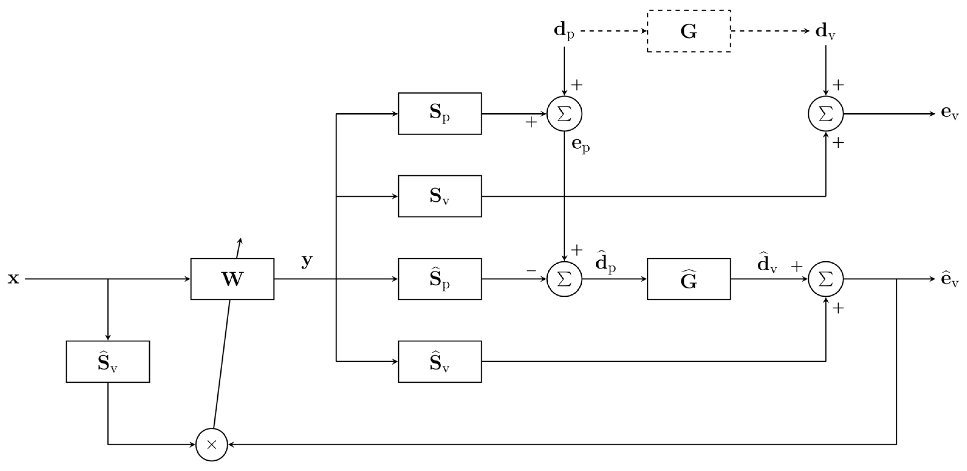
2.3. Active Control System with Remote Microphone Technique
2.4. Robustness Optimization Method
3. Simulations
3.1. Transfer Response Analysis
3.2. System Performance
3.3. Influence of Different Parameters
4. Experiments
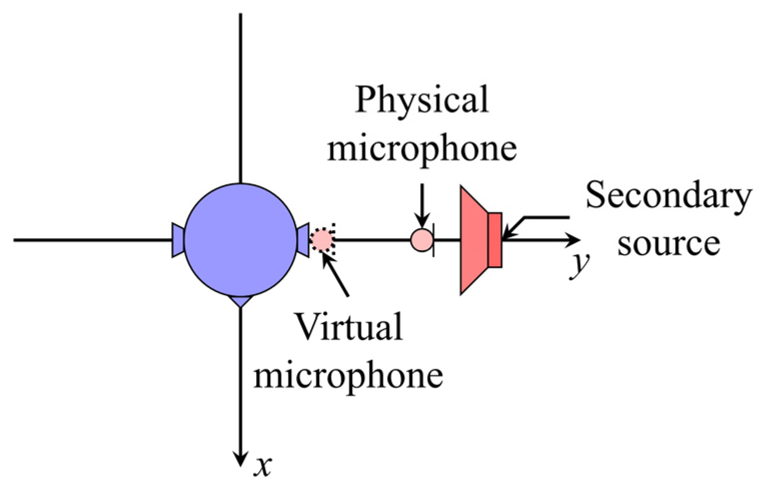
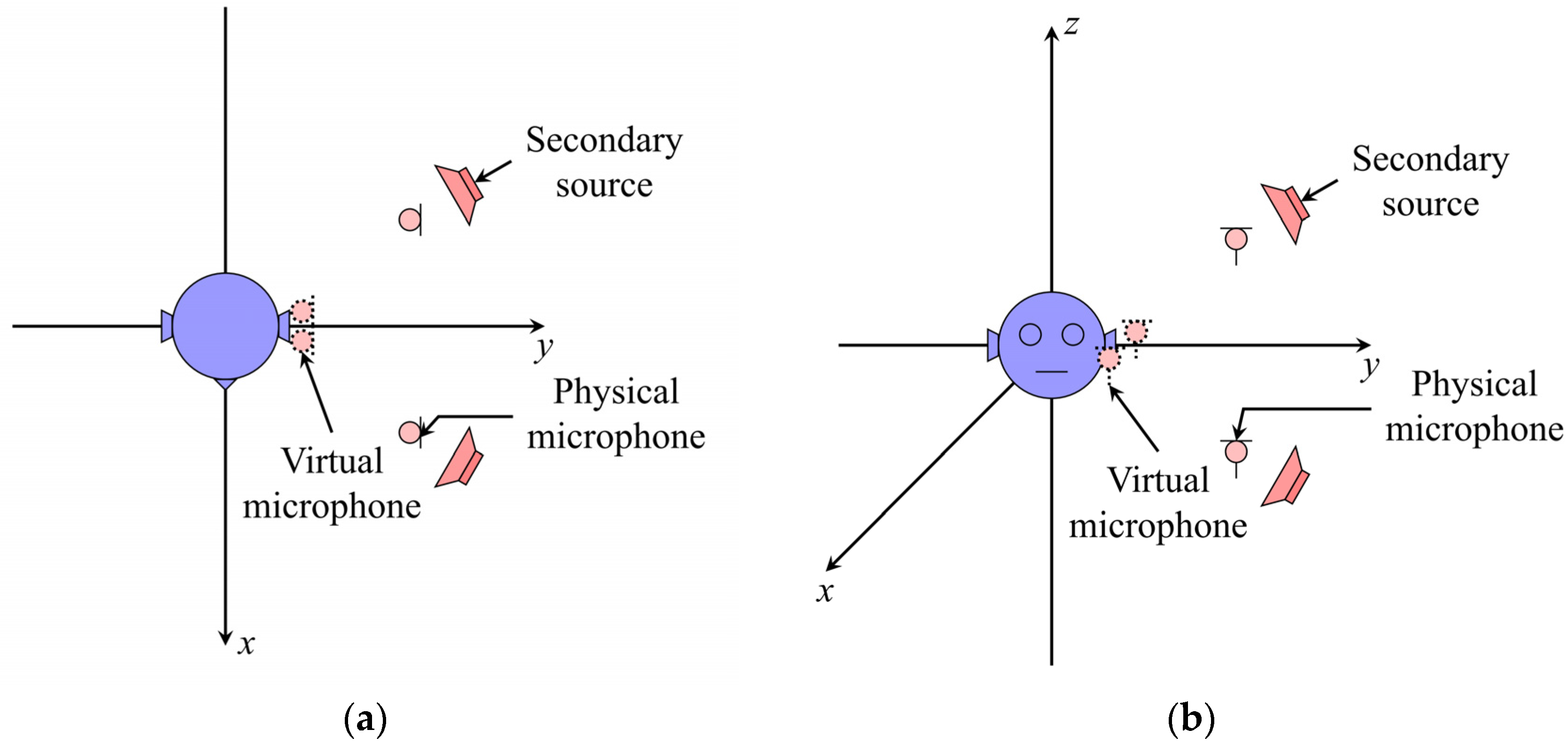
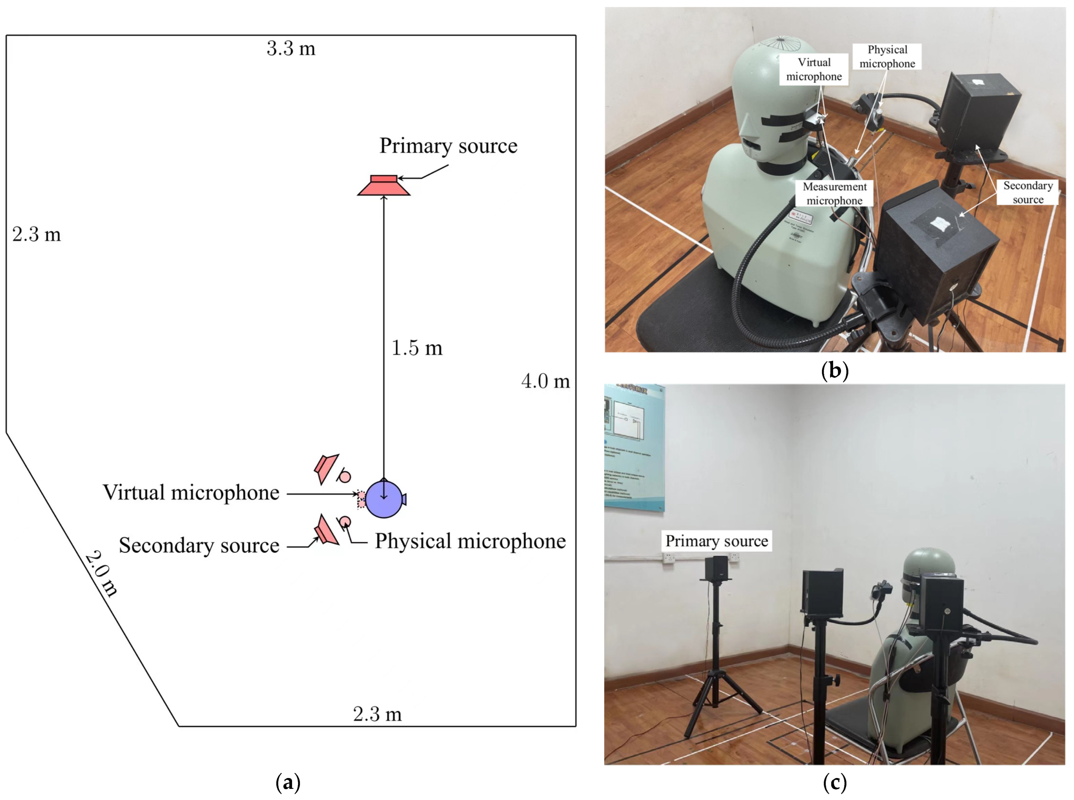
4.1. Setup
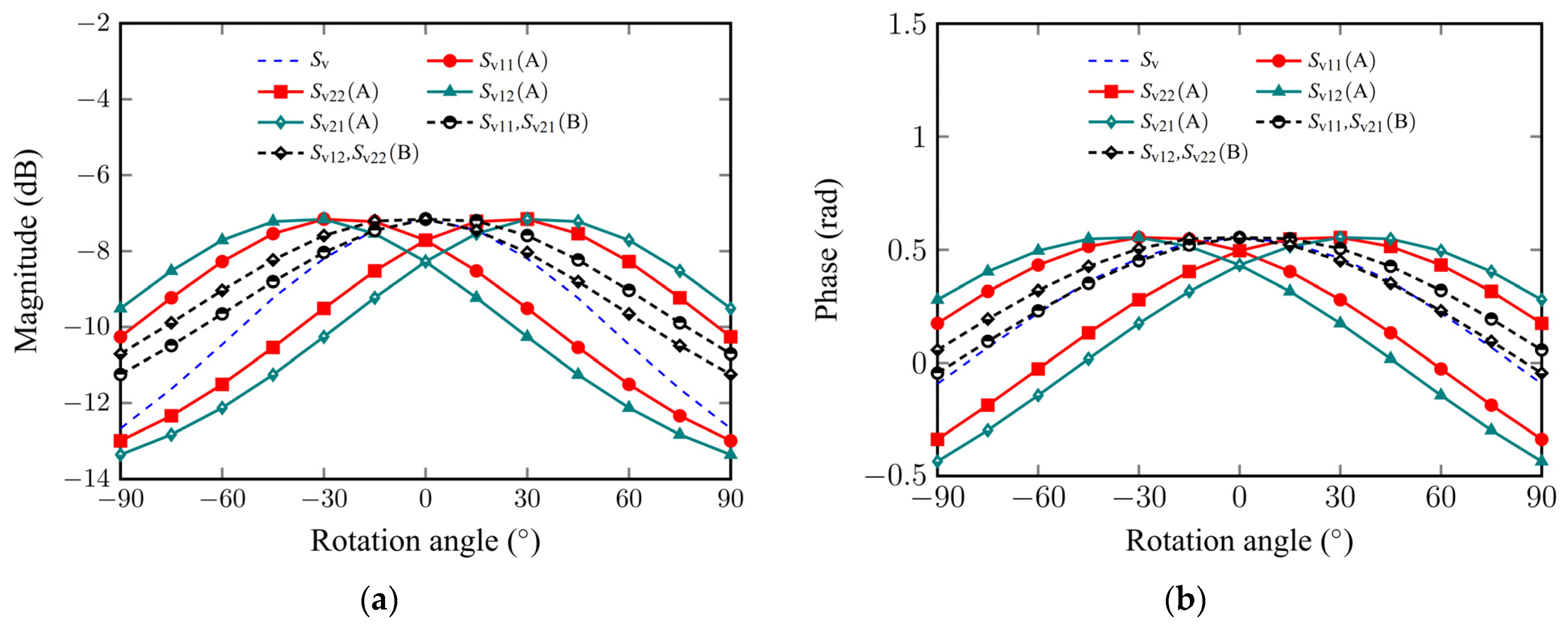
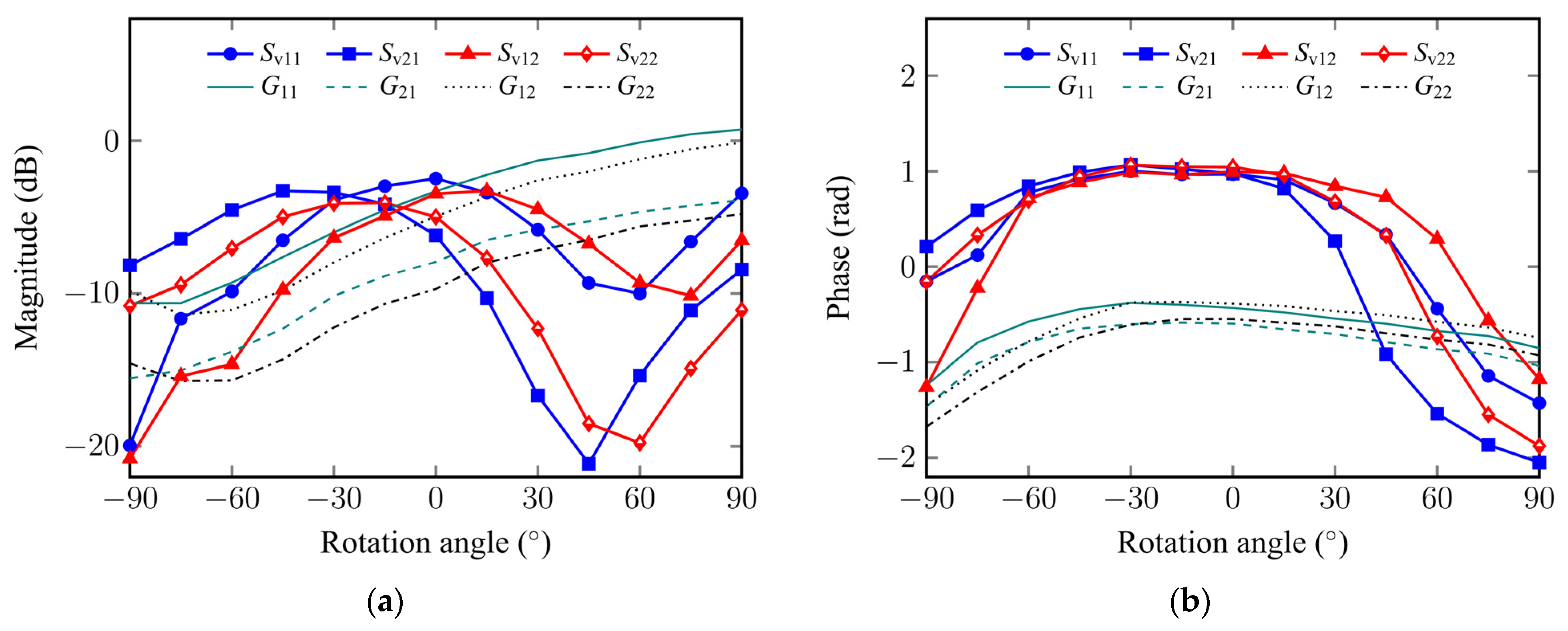
4.2. Analysis of Acoustic Transfer Responses
4.3. Noise Control Performance
5. Conclusions
Author Contributions
Funding
Institutional Review Board Statement
Informed Consent Statement
Conflicts of Interest
References
- Olson, H.F.; May, E.G. Electronic sound absorber. J. Acoust. Soc. Am. 1953, 25, 1130–1136. [Google Scholar] [CrossRef]
- Diaz, J.; Egaña, J.M.; Viñolas, J. A local active noise control system based on a virtual microphone technique for railway sleeping vehicle applications. Mech. Syst. Signal Process. 2006, 20, 2259–2276. [Google Scholar] [CrossRef]
- Buck, J.; Jukkert, S.; Sachau, D. Performance evaluation of an active headrest considering non-stationary broadband disturbances and head movement. J. Acoust. Soc. Am. 2018, 143, 2571–2579. [Google Scholar] [CrossRef] [PubMed]
- Jung, W.; Elliott, S.J.; Cheer, J. Local active control of road noise inside a vehicle. Mech. Syst. Signal Process. 2019, 121, 144–157. [Google Scholar] [CrossRef] [Green Version]
- Elliott, S.J.; Joseph, P.; Bullmore, A.J.; Nelson, P.A. Active cancellation at a point in a pure-tone diffuse sound field. J. Sound Vib. 1988, 120, 183–189. [Google Scholar] [CrossRef]
- David, A.; Elliott, S.J. Numerical studies of actively generated quiet zones. Appl. Acoust. 1994, 41, 63–79. [Google Scholar] [CrossRef]
- Joseph, P.; Elliott, S.J.; Nelson, P.A. Near field zones of quiet. J. Sound Vib. 1994, 172, 605–627. [Google Scholar] [CrossRef]
- Elliott, S.J.; David, A. A virtual microphone arrangement for local active sound control. In Proceedings of the 1st International Conference on Motion & Vibration Control, Yokohama, Japan, 7–11 September 1992. [Google Scholar]
- Jung, W.; Elliott, S.J.; Cheer, J. Combining the remote microphone technique with head-tracking for local active sound control. J. Acoust. Soc. Am. 2017, 142, 298–307. [Google Scholar] [CrossRef] [PubMed] [Green Version]
- Zhang, Z.Q.; Wu, M.; Yin, L.; Gong, C.; Wang, J.J.; Zhou, S.; Yang, J. Robust feedback controller combined with the remote microphone method for broadband active noise control in headrest. Appl. Acoust. 2022, 195, 108815. [Google Scholar] [CrossRef]
- Cazzolato, B.S. Sensing Systems for Active Control of Sound Transmission into Cavities. Ph.D. Theses, University of Adelaide, Adelaide, Australia, 1999. [Google Scholar]
- Petersen, C.D.; Fraanje, R.; Cazzolato, B.S.; Zander, A.C.; Hansen, C.H. A Kalman filter approach to virtual sensing for active noise control. Mech. Syst. Signal Process. 2008, 22, 490–508. [Google Scholar] [CrossRef]
- Petersen, C.D.; Zander, A.C.; Cazzolato, B.S.; Hansen, C.H. A moving zone of quiet for narrowband noise in a one-dimensional duct using virtual sensing. J. Acoust. Soc. Am. 2007, 121, 1459–1470. [Google Scholar] [CrossRef] [PubMed] [Green Version]
- Lei, C.Y.; Xu, J.; Wang, J.; Zheng, C.S.; Li, X.D. Active headrest with robust Performance against head movement. J. Low Freq. Noise Vib. Act. Control 2015, 34, 233–250. [Google Scholar] [CrossRef] [Green Version]
- Han, R.; Wu, M.; Gong, C.; Jia, S.; Han, T.; Sun, H.; Yang, J. Combination of robust algorithm and head-tracking for a feedforward active headrest. Appl. Sci. 2019, 9, 1760. [Google Scholar] [CrossRef] [Green Version]
- Pawelczyk, M. Multiple input multiple output adaptive feedback control strategies for the active headrest system: Design and real-time implementation. Int. J. Adapt. Control Signal Processing 2003, 17, 785–800. [Google Scholar] [CrossRef]
- Elliott, S.; Sutton, T. Performance of feedforward and feedback systems for active control. Speech Audio Processing IEEE Trans. 1996, 4, 214–223. [Google Scholar]
- Cheer, J.; Elliott, S.J. Multichannel control systems for the attenuation of interior road noise in vehicles. Mech. Syst. Signal Process. 2015, 60–61, 753–769. [Google Scholar] [CrossRef] [Green Version]
- Zhang, Z.Q.; Wu, M.; Gong, C.; Yin, L.; Yang, J. Adjustable Structure for Feedback Active Headrest System Using the Virtual Microphone Method. Appl. Sci. 2021, 11, 5033. [Google Scholar] [CrossRef]
- Bowman, J.J.; Senior, T.B.A.; Uslenghi, P.L.E. Electromagnetic and Acoustic Scattering by Simple Shapes; New York Hemisphere Publishing Corp P: Washington, DC, USA, 1987; Volume 1. [Google Scholar]
- Brayton, R.K.; Director, S.W.; Machtel, G.D.; Vidigal, L.M. A new algorithm for statistical circuit design based on quasi-newton methods and function splitting. IEEE Trans. Circuits Syst. II Analog. Digit. Signal Processing 1979, 26, 784–789. [Google Scholar] [CrossRef]
- Srinivas, M.; Patnaik, L.M. Adaptive probabilities of crossover and mutation in genetic algorithms. IEEE Trans. Syst. Man Cybern. 1994, 24, 656–667. [Google Scholar] [CrossRef] [Green Version]
- Coello, C.A.C.; Pulido, G.T.; Lechuga, M.S. Handling multiple objectives with particle swarm optimization. IEEE Trans. Evol. Comput. 2004, 8, 256–279. [Google Scholar] [CrossRef]


Publisher’s Note: MDPI stays neutral with regard to jurisdictional claims in published maps and institutional affiliations. |
© 2022 by the authors. Licensee MDPI, Basel, Switzerland. This article is an open access article distributed under the terms and conditions of the Creative Commons Attribution (CC BY) license (https://creativecommons.org/licenses/by/4.0/).
Share and Cite
Chen, H.; Huang, X.; Zou, H.; Lu, J. Research on the Robustness of Active Headrest with Virtual Microphones to Human Head Rotation. Appl. Sci. 2022, 12, 11506. https://doi.org/10.3390/app122211506
Chen H, Huang X, Zou H, Lu J. Research on the Robustness of Active Headrest with Virtual Microphones to Human Head Rotation. Applied Sciences. 2022; 12(22):11506. https://doi.org/10.3390/app122211506
Chicago/Turabian StyleChen, Hongyu, Xiaofan Huang, Haishan Zou, and Jing Lu. 2022. "Research on the Robustness of Active Headrest with Virtual Microphones to Human Head Rotation" Applied Sciences 12, no. 22: 11506. https://doi.org/10.3390/app122211506