Abstract
The problem that is addressed here is that of a circular thin plate clamped peripherally with frictionless contact to an elastic sphere. A complete and effective solution to this problem is developed to describe the relationship between the contact force and the relative penetration. Analysis of the contact stress and surface displacements of the plate and the sphere is carried out. Comparison of the results with the Hertz theory indicates that the former predicts relative penetration with more accuracy, which indicates that the Hertz theory is not applicable to the elastic sphere in contact with the circular thin plate with a large deformation. In addition, the results of the theoretical model show good agreement with the ANSYS simulation results.
1. Introduction
Many researchers have adopted Hertz theory [1,2] to deal with different problems of contact. Dubowsky et al. [3,4] utilized Hertz theory for the contact problem of revolute joints with clearance and presented an impact pair model to represent the contact force at the contact surfaces. Guess and Maletsky [5] used the Hertz contact approach to evaluate the contact force which develops in the patellofemoral and tibiofemoral connections within a dynamic knee simulator for modeling total knee prosthesis. Ignacio et al. [6] proposed an analytical approach for the stress analysis of gear drives with localized bearing contact based on the Hertz theory. Sanders and Brannon [7] examined the hypothesis that the contact dimensions of edge-loaded ceramic and metal hip bearings can be accurately estimated using the Hertz theory. Jiang et al. [8] verified the applicability of the Hertz theory by comparing the theoretical results from the Hertz contact model and the simulated results from the quasicontinuum method.
All the above works indicate that the Hertz theory is good enough for the case of small deformation contact. However, it is not applicable to the elastic sphere in contact with the thin plate with large deformation. This is due to the fact that the elastic strain energy is determined by the membrane stresses that result from the large out-of-plane deflections of the thin plate. Consequently, geometrical nonlinearity has to be considered, and detailed analysis need to be performed. Many researchers have performed theoretical, numerical, and experimental studies on the behavior of thin plates subjected to impulsive loadings [9,10,11,12,13,14,15,16,17,18,19]. This research primarily focused on the behavior of thin plates subjected to impulsive loadings. However, there is no literature at present investigating the exact closed-form solution to the problem of an elastic sphere in contact with a circular thin plate.
In this paper, a circular thin plate clamped peripherally with frictionless contact to an elastic sphere is studied. Firstly, a set of equations is established to predict the relationship between the contact force and the relative penetration. On this basis, analysis of the contact stress and surface displacements of the circular thin plate and the elastic sphere is carried out. Then, comparison of the results with the Hertz theory is presented. Finally, the validity of the methodology developed is examined by comparing the theoretical results with the finite element method.
2. Formulation and Governing Equations
2.1. Contact Analysis
As shown in Figure 1, a circular thin plate and an elastic sphere bounded by surfaces S1, S2, and frictionless contact at point O1 were considered. The circular thin plate was clamped peripherally. Taking point O1 as the origin of the coordinate system, we directed axes z1, z2, which were perpendicular to the common tangent plane to surfaces S1 and S2 at point O1 into each of the bodies. Under the action of force P, the two bodies were deformed in the region adjacent to the place of contact and were brought closer together. Let δ1 and δ2 denote the projections of the translation displacement of the circular thin plate and the sphere on axes z1 and z2. One can also determine δ1 and δ2 as the displacements of the points of the circular thin plate and the sphere provided that these points are well away from the contact place. The value
is referred to as the approach.

Figure 1.
An elastic sphere contacting with a circular thin plate.
Let us consider two points M1 and M2 on the circular thin plate and the sphere, respectively, which lie on the joint perpendicular to the common tangent plane in the region adjacent to the contact place. Before the deformation, the distance from point M1 to axis z1 is r, as is is point M2 to axis z2, and the distance between the two points is z2. Therefore, the equation for point M2 is presented in the form
where rb is the radius of the sphere. Then, z2 can be expressed as
When the bodies are deformed, the projections of the displacements of points M1 and M2 on axes z1 and z2 are w1 and w2, respectively. Simultaneously, points M1 and M2 move together with the bodies and take positions and , respectively. Thus, after the deformation, the coordinates of points and are denoted as follows
Then, the distance can be equal to
or by Equations (1) and (3)
For those points M1 and M2, which will be in contact after the deformation, this distance will be zero, whereas this distance is positive for the points in the neighborhood of the contact place. The surface of the contact can therefore be determined as a locus, where
The exact expressions of w1 and w2 are discussed in later sections of the text.
There is a normal stress q(r) on the contact surface, while the shear stresses are assumed to be absent. Furthermore, it is assumed that when considering the local effects in the vicinity of the contact, the contacting bodies can be replaced by an elastic half-space pressed against a circular thin plate on the plane surface lying in the tangent plane of surfaces S1 and S2. On this plane, , and the area of contact is a circle of radius b (see Figure 2). Whilst the stress to the area of contact between the two bodies can be assumed as [1]
where q0 is the maximal contact pressure at the center of the circular contact area determined by
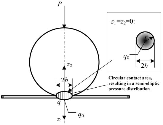
Figure 2.
Contact area.
2.2. Contact Deformation of the Sphere
Consider the force element qds acting normal to the circular contact area of the sphere, as shown in Figure 3. A rectangular coordinate system (obxyz) is established with the center of the area element ds as origin.
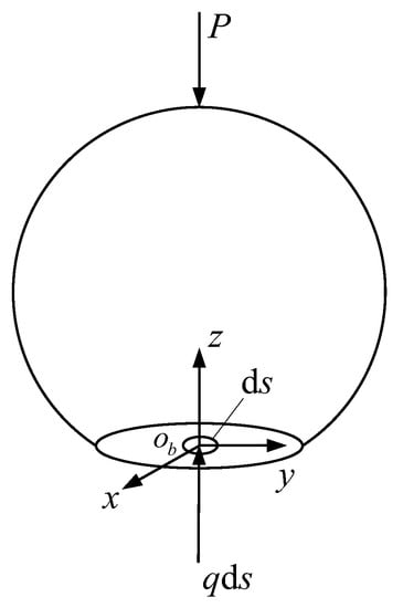
Figure 3.
Force element qds acting normal to the circular contact area of the sphere.
Because the problem is axisymmetric, it is necessary to use the cylindrical coordinate (ρ, φ, and z), and all the field quantities are independent of the angular coordinate. For such a system, the stress components are defined on the differential element by dropping all φ-terms shown in Figure 4.
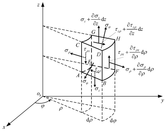
Figure 4.
Stress components in cylindrical coordinates.
By applying the equilibrium principle to the differential element, the equilibrium equations with zero body forces can be expressed as follows [20]
Thus, all elasticity stress fields must satisfy these relations in order to be in static equilibrium.
For the axisymmetric case, the displacement field is of the form , , and . Therefore, the strain field is given by
According to the generalized Hooke’s law for linear isotropic elastic solids, the stress–strain relations can be written as
where , and Eb, μb, and Gb are the Young’s modulus, Poisson ratio, and shear modulus of the sphere, respectively.
Combining Relations (11)~(14), we can obtain the equilibrium equations solely in terms of displacements denoted as
where the Laplacian is given by .
This system is difficult to solve, and additional mathematical techniques have been developed to further simplify these equations for problem solution. Common methods normally employ the use of displacement potential functions [21]. Here, we use the Love–Boussinesq potential defined by
where , A1, and A2 are constants to be determined.
The displacement fields corresponding to the potential can be written in the form
By combining Equations (14), (16) and (17), we can obtain
The boundary conditions on the free surface require that everywhere except at the origin, and the summation of the total vertical force is equal to qds. In Equation (18), note that the expression for σz vanishes on z = 0 but is indeterminate at the origin; thus, this relation will not directly provide a means to determine A1 and A2. Rather than trying to evaluate this singularity at the origin, we pursue the integrated condition on any typical plane z = constant
Invoking the boundary conditions determines the two constants
Then, the results for the displacements and stresses are given by
Therefore, we can obtain the vertical displacement of a random point on the circular contact area under force element qds
Next, we consider the distributed load q(r) acting normal to the circular contact area. The vertical displacement of point M2 with the distance of r to the center of the circular contact area Op can be obtained by integrating over the loading region. As shown in Figure 5, the area of the shadow region represented by ds is ρdψdρ; then, we can obtain
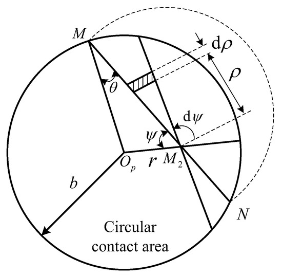
Figure 5.
Analysis of the vertical displacement of point M2.
Note that the distance is equal to ; thus, by substituting Equation (9) into Equation (23), the vertical displacement of point M2 can be expressed as
2.3. Contact Deformation of the Circular Thin Plate
We now proceed to a discussion on the large deformation of the circular thin plate under the axisymmetric transverse distributed load q(r).
As shown in Figure 6, point o is the center of the middle plane of the circular thin plate, and r denotes the radial coordinate. The governing equations of axisymmetric large deflection bending of the circular thin plate with radius a and thickness h take the forms of [22]
in which is the flexural rigidity of the plate; w is the deflection of the plate; Nr is the radial stress per unit length; and E and μ are the Young’s modulus and Poisson ratio of the plate, respectively. The boundary conditions of the plate can be written as
where u is the radial displacement of the plate.
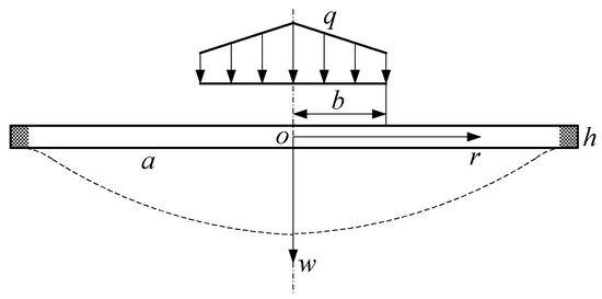
Figure 6.
Contact deformation analysis of the circular thin plate.
With the aid of the following dimensionless parameters
Equations (25) and (26) can be reduced into
and
When , we can obtain the expression of by substituting Equation (9) into Equation (27)
In the above equation, it should be noted that is a polynomial with respect to y. Hence, the exact solution to Equation (28) for this case can be given by [23,24]
where ai and bi are the constant coefficients to be determined. Then, the deflection of the circular thin plate on the contact area can be obtained from Equations (27) and (31)
where C1 is also an arbitrary constant to be determined.
Furthermore, considering the case of , the expression of is written as
Under this condition, the exact solution to Equation (28) can be expressed as follows [24,25,26]
where the constant coefficients Aij and Bij can be determined by the boundary condition of . The deflection of the circular thin plate on the external contact area can then be obtained by combining Equations (27) and (34)
Substituting Equations (24) and (32) into Equation (8) yields
Because this relation must be satisfied for all values of r, equating the like powers of ri gives the results
Assuming that w(r) and w’(r) are both continuous across the interface , we have
and
Accordingly, the relationship between the contact force F and the relative penetration δ can be obtained from Equations (37)–(39).
3. Results and Discussion
In order to compare the results derived in the paper with the Hertz theory, we take a case as an example, and the parameters for calculation are listed in Table 1.

Table 1.
Parameters for calculation.
Figure 7 shows the deflection of the whole circular thin plate. Figure 8 shows the deflection of the circular thin plate on the contact area in detail. As can be seen from these figures, the deflection of the circular thin plate presents in an axisymmetric distribution, and varies in a continuous and nonlinear manner, which initiates from zero at the boundary and reaches the peak value of 0.5377 mm at the center. Additionally, the radius of the contact area is 0.2616 mm.
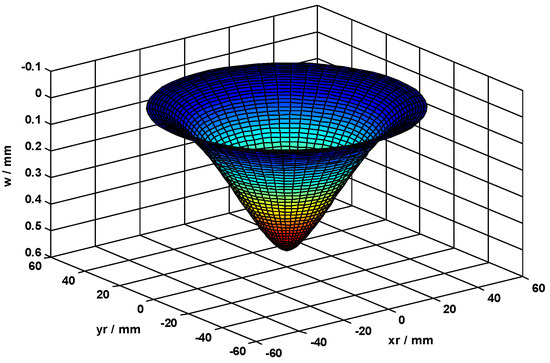
Figure 7.
Deflection of the circular thin plate.
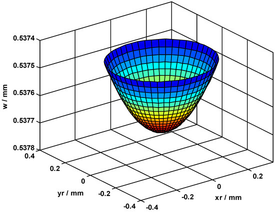
Figure 8.
Deflection of the circular thin plate on the contact area.
Furthermore, the normal stress on the circular thin plate also presents an axisymmetric distribution, which initiates from zero at the boundary of the contact area and reaches the peak value of 0.544Gpa at the center (see Figure 9).
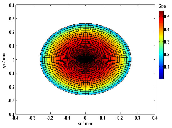
Figure 9.
Normal stress distribution on the circular thin plate.
A comparison between the results based on the Hertz theory and ours is presented in Table 2. The relative penetration derived in the paper is less than 1% of that given by the Hertz theory in the case of identical force, while the radius of the contact area does not change significantly. Therefore, according to the data presented, we can conclude that the Hertz theory is not applicable to the elastic sphere in contact with the thin plate with large deformation.
Table 2.
Comparison results.
Next, the validity of the results derived in the paper were verified by the finite element method. The finite element software ANSYS was introduced to be the simulation tool. ANSYS is a general-purpose finite element program for static and dynamic, as well as multiphysics analysis and specializes in contact related problems. Figure 10 exhibits the finite element models of the sphere and the circular thin plate by ANSYS. All the model components were meshed with the element SOLID185, a 3D element of eight nodes and three degrees of freedom per node (displacements in nodal directions x, y, and z) [27]. This element had plasticity, large deflection, and large strain capabilities. The mesh at the contact locations was refined very well to accurately model the contact region, as also shown in Figure 10. The contact between the sphere and the circular thin plate was modeled using CONTA173 elements placed on the sphere and TARGE170 elements placed on the circular thin plate.
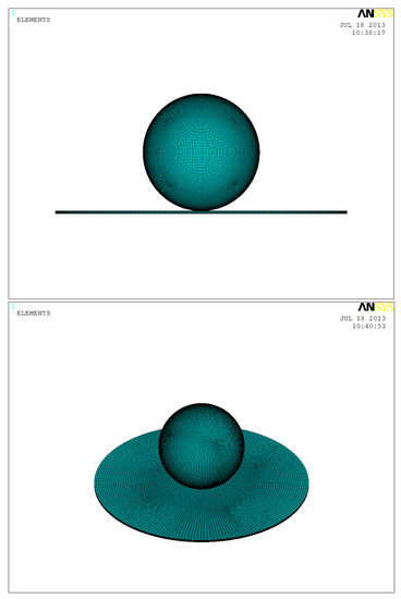
Figure 10.
Finite element models.
The deflection of the whole plate and the normal stress on the plate variation with respect to the radial coordinate r obtained theoretically and numerically can be seen in Figure 11 and Figure 12. As these figures demonstrate, the theoretical and numerical results were in good agreement, and the relative deviation was in the acceptable range. Therefore, the theoretical model presented in this paper was fully verified.
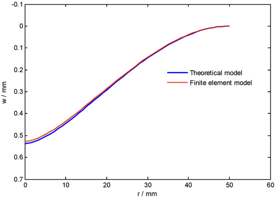
Figure 11.
Deflection of the circular thin plate vs. r.
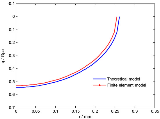
Figure 12.
Normal stress on the circular thin plate vs. r.
4. Conclusions
In this paper, we derived a new solution to the problem of a circular thin plate clamped peripherally with frictionless contact to an elastic sphere. A set of equations were established to predict the relationship between the contact force and the relative penetration. On this basis, analysis of the contact stress and surface displacements of the circular thin plate and the elastic sphere was carried out. Furthermore, a comparison of the results with the Hertz theory was presented. We can conclude that, firstly, the deflection of the circular thin plate presented in an axisymmetric distribution and varied in a continuous and nonlinear manner, which initiated from zero at the boundary and reached the peak value at the center. Secondly, the normal stress on the circular thin plate also presented in an axisymmetric distribution. Lastly, the relative penetration derived in the paper was less than 1% of that given by the Hertz theory in the case of identical force, while the radius of the contact area did not change significantly, which indicates that the Hertz theory is not applicable to the elastic sphere in contact with the circular thin plate with large deformation. In addition, the process of contact was simulated by using the finite element software ANSYS in order to verify the correctness of the theoretical model. The results of the theoretical model showed good agreement with the ANSYS simulation results. In future research, an impact experimental system will be designed in order to prove the correctness of the large deformation contact theory proposed in this paper.
Author Contributions
Conceptualization, D.X.; Investigation, Y.H.; Writing—original draft, W.H.; Writing—review & editing, Y.Y.; Supervision, X.C. All authors have read and agreed to the published version of the manuscript.
Funding
This research received no external funding.
Institutional Review Board Statement
Not applicable.
Informed Consent Statement
Informed consent was obtained from all subjects involved in the study.
Conflicts of Interest
The authors declare no conflict of interest.
References
- Hertz, H. Über die Berührung fester elastischer Körper. J. Reine Angew. Math. 1881, 92, 156–171. [Google Scholar]
- Zhupanska, O.I. Contact problem for elastic spheres: Applicability of the Hertz theory to non-small contact areas. Int. J. Eng. Sci. 2011, 49, 576–588. [Google Scholar] [CrossRef]
- Dubowsky, S.; Freudenstein, F. Dynamic analysis of mechanical systems with clearances, Part 1: Formulation of dynamic model. J. Eng. Ind. 1971, 93, 305–309. [Google Scholar] [CrossRef]
- Deck, J.F.; Dubowsky, S. On the limitations of predictions of the dynamic response of machines with clearance connections. ASME J. Mech. Des. 1994, 116, 833–841. [Google Scholar] [CrossRef]
- Guess, T.M.; Maletsky, L.P. Computational modelling of a total knee prosthetic loaded in a dynamic knee simulator. Medial Eng. Phys. 2005, 27, 357–367. [Google Scholar] [CrossRef]
- Gonzalez-Perez, I.; Iserte, J.L.; Fuentes, A. Implementation of Hertz theory and validation of a finite element model for stress analysis of gear drives with localized bearing contact. Mech. Mach. Theory 2011, 46, 765–783. [Google Scholar] [CrossRef]
- Sanders, A.P.; Brannon, R.M. Assessment of the applicability of the Hertzian contact theory to edge-loaded prosthetic hip bearings. J. Biomech. 2012, 44, 2802–2808. [Google Scholar] [CrossRef]
- Jiang, W.G.; Wang, Z.W.; Li, J.W. Verification of the applicability of classical contact theories for nanoscale contact problems using multiscale simulation. Comput. Mater. Sci. 2012, 60, 186–193. [Google Scholar] [CrossRef]
- Xia, M.H.; Bi, X.H.; Chang, J.C. The Calculation equation for four-edged rectangular plates with work reciprocal theorem of bending thin plates with large deflections. J. Tangshan Coll. 2004, 17, 77–80. [Google Scholar]
- Bakker, M.C.M.; Rosmanit, M.; Hofmeyer, H. Approximate large-deflection analysis of simply supported rectangular plates under transverse loading using plate post-buckling solutions. Thin Walled Struct. 2008, 46, 1224–1235. [Google Scholar] [CrossRef]
- Wierzbizki, T.; Nurick, G.N. Large deformation of thin plates under localized impulsive loading. Int. J. Impact Eng. 1996, 18, 899–918. [Google Scholar] [CrossRef]
- Lee, Y.W.; Woertz, J.C.; Wierzbizki, T. Fracture prediction of thin plates under hemi-spherical punch with calibration and experimental verification. Int. J. Impact Eng. 2004, 46, 751–781. [Google Scholar] [CrossRef]
- Gohari, S.; Sharifi, S.; Burvill, C.; Mouloodi, S.; Izadifar, M.; Thissen, P. Localized failure analysis of internally pressurized laminated ellipsoidal woven GFRP composite domes: Analytical, numerical, and experimental studies. Arch. Civ. Mech. Eng. 2019, 19, 1235–1250. [Google Scholar] [CrossRef]
- Gohari, S.; Mozafari, F.; Moslemi, N.; Mouloodi, S.; Alebrahim, R.; Ahmed, M.; Abdi, B.; Sudin, I.; Burvill, C. Static and dynamic deformation response of smart laminated composite plates induced by inclined piezoelectric actuators. J. Compos. Mater. 2022, 56, 1–25. [Google Scholar] [CrossRef]
- Das, R.; Mishra, S.C.; Ajith, M.; Uppaluri, R. An inverse analysis of a transient 2-D conduction–radiation problem using the lattice Boltzmann method and the finite volume method coupled with the genetic algorithm. J. Quant. Spectrosc. Radiat. Transf. 2008, 109, 2060–2077. [Google Scholar] [CrossRef]
- Singla, R.K.; Das, R. Application of Adomian decomposition method and inverse solution for a fin with variable thermal conductivity and heat generation. Int. J. Heat Mass Transf. 2013, 66, 496–506. [Google Scholar] [CrossRef]
- Keer, L.M.; Miller, G.R. Contact between an elastically supported circular plate and a rigid indenter. Int. J. Eng. Sci. 1983, 21, 681–690. [Google Scholar] [CrossRef]
- Thredgold, J.M.; Lucas, S.K.; Howlett, P.G. On the contact of a rigid sphere and a thin plate. Math. Comput. Model. 2006, 43, 119–131. [Google Scholar] [CrossRef]
- Li, M.; Ru, C.Q.; Gao, C.F. Axisymmetric indentation of an elastic thin plate by a rigid sphere revisited. ZAMM J. Appl. Math. Mech. Z. Angew. Math. Mech. 2018, 98, 1436–1446. [Google Scholar] [CrossRef]
- Sadd, M.H. Elasticity: Theory, Applications, and Numerics; Academic Press: Oxford, UK, 2004. [Google Scholar]
- Lurie, A.I.; Belyaev, A. Theory of Elasticity; Springer: Berlin, Germany, 2005. [Google Scholar]
- Timoshenko, S.; Woinowsky-Krieger, S. Theory of Plates and Shells; McGraw-Hill: New York, NY, USA, 1959. [Google Scholar]
- Zheng, X.J.; Zhou, Y.H. On the problem of transition from von Karman plate equations to theory of membrane. J. Lanzhou Univ. 1991, 27, 18–25. (In Chinese) [Google Scholar]
- Zheng, X.J. Large Deflection Theory and Application of Circular Thin Plates; Jilin Science and Technology Press: Changchun, China, 1990. (In Chinese) [Google Scholar]
- Zheng, X.J.; Zhou, Y.H. Exact solution to large deflection of circular plates under compound loads. Sci. China 1987, 30, 391–404. [Google Scholar]
- Zheng, X.J.; Zhou, Y.H. On analytical-computerized method to solve nonlinear bending problem of circular plate under a concentrated load. Appl. Math. Mech. 1987, 8, 759–766. [Google Scholar]
- ANSYS Release 10.0 Documentation, Element Reference; ANSYS Inc.: Canonsburg, PA, USA, 2005.


Publisher’s Note: MDPI stays neutral with regard to jurisdictional claims in published maps and institutional affiliations. |
© 2022 by the authors. Licensee MDPI, Basel, Switzerland. This article is an open access article distributed under the terms and conditions of the Creative Commons Attribution (CC BY) license (https://creativecommons.org/licenses/by/4.0/).