Article

Seismic Assessment and Retrofitting of an Historical Masonry Building Damaged during the 2016 Centro Italia Seismic Event

1
Department of Civil, Environmental Engineering and Architecture, University of Cagliari, 09123 Cagliari, Italy
2
Department of Architecture, Built Environment and Construction Engineering, Politecnico di Milano, 20133 Milano, Italy
*
Author to whom correspondence should be addressed.
Appl. Sci. 2022, 12(22), 11789; https://doi.org/10.3390/app122211789
Submission received: 3 November 2022 / Revised: 16 November 2022 / Accepted: 18 November 2022 / Published: 20 November 2022
(This article belongs to the Special Issue Advanced Seismic Evaluation of Relevant Architectures)

Abstract

:
The preservation and definition of the correct retrofitting interventions of historic masonry buildings represents a relevant topic nowadays, especially in a country characterized by high seismicity zones. Considering the Italian Cultural Heritage, most of these buildings are constructed in ancient unreinforced masonry (URM) and showed a high level of vulnerability during the recent 2009 (L’Aquila), 2012 (Emilia Romagna) and 2016 (Centro Italia) earthquakes. In this paper, the seismic assessment of an historic masonry building damaged during 2016 Centro Italia seismic event is presented considering different types of retrofitting interventions. Starting from the results obtained by the post-earthquake survey, different finite element models have been implemented to perform linear and non-linear analyses useful to understand the seismic behaviour of the building and to define the appropriate retrofitting interventions. In particular, reinforced plaster layer and cement-based grout injections have been applied in each masonry wall of the building in order to improve their horizontal load-bearing capacity, and an additional wall made with Poroton blocks and M10 cement mortar has been built adjacent to the central stairwell. In addition, in view of the need to replace the roof seriously damaged during the seismic event, a cross-laminated roof solution characterized by a thickness equal to 14 cm (composed by seven layers, each 2 cm thick) has been proposed. The results show that the proposed retrofitting interventions have led to a significant improvement in the seismic behaviour of the building.

1. Introduction

During the last decades, different strong earthquake events occurred in Italy, e.g., 2009 (L’Aquila) [1,2,3], 2012 (Emilia-Romagna) [4], 2016 (Centro Italia) [5,6] and 2017 (Ischia) [7] seismic events, where several historical buildings realized in ancient unreinforced masonry (URM) suffered serious damages. In fact, these constructions were designed to resist mainly the gravity loads: they are generally characterized by slender walls, flexible horizontal floors, bad quality of the masonry, bad interlocking among perpendicular walls and between walls and roof, absence of tie-beams used to absorb the thrusts of arches and vaults [8].
Considering their wide diffusion and their high seismic vulnerability, the structural safety of existing URM buildings is a very topical issue. In Italy, and more in general in the Mediterranean area, a huge amount of such buildings belongs to the historical architectural heritage, and their conservation is needed both for the importance of their cultural value as well as for the functions that they still perform up to now. Moreover, in many developing countries such structural typology is still adopted now and commonly used, so a huge amount of residential and civil buildings around the world are built in URM. For such reasons, in the last decades, much attention has been paid to URM buildings to assess their structural safety and to define appropriate intervention of retrofitting [9,10,11,12].
Despite the important research works devoted to the study of the mechanical behavior of URM structures carried out by several researchers in the last few years—a complete overview of the different modelling strategies for the computational analysis of such structures has been provided in [13]—the correct evaluation of the seismic behavior of masonry structures, which is useful to define the retrofitting interventions, remains still an open issue.
As it is well known, masonry is a composite structural material obtained by assembling natural or artificial blocks by means of mortar layers or dry joints. Difficulties in modeling are related to heterogeneity, anisotropy and to some peculiar features of masonry material, whose mechanical behavior depends on several parameters that are difficult to assess, such as mechanical properties of constituent materials, arrangement of units, thickness of joints, presence of internal filling with relative unknowns and difficulties in describing connections between external layers, manufacturing imperfections, state of conservation, etc. In order to take into account these characteristics, several methodologies have been proposed in the scientific literature [14]; however, the use of refined models is usually limited to the research field, while in the common practice simplified approaches are more diffused. Such approaches usually rely on the description of the structure as an assemblage of its structural elements modelled by means of macroelements, requiring a small number of mechanical parameters and low computational effort.
Considering structural assessment of URM buildings, different approaches have been proposed for the evaluation of their seismic vulnerability, among which numerical analyses stand out for their diffusion and applicability to both monumental and so-called minor architectures [15,16]. In particular, the implementation of appropriate Finite Element models (FEM) represents one of the most suitable approaches for their ability to analyze even complex structures. It must be noticed that, due to its complex inner microstructure, the masonry shows a different behavior in compression and tension, therefore, because of the very low tensile strength of masonry material, URM buildings exhibit a non-linear behavior even at early stages of seismic loading, calling for the adoption of nonlinear analyses. Among them, dynamic nonlinear analyses may provide the most reliable prediction of the structural seismic behavior; however, they are scarcely employed in practice because of the required computational efforts and the difficulties in acquiring data (such as seismic input or material parameters to be used); therefore, in this case, their adoption is limited to specialized practitioners. For this reason, simplified nonlinear static analysis has been developed in the late 70’s [17] in order to overcome such difficulties and with the target to provide easy-to-use computational tools for common practitioners as well. Nonlinear static analysis allows to evaluate the base shear-top displacement capacity curve under an incremental horizontal load profile, providing an evaluation of the performance point obtained by the intersection of the capacity curve with the displacement seismic demand.
Nowadays, in common practice, nonlinear static analyses are combined with simplified structural models comprised by macroelements. Among the available modelling strategies which can be properly adopted, the so-called Equivalent Frame Method (EFM) [18] is the most widely used for seismic assessment of large URM buildings [19], which is characterized by regular geometry is based on the adoption of macroelements to discretize walls as an assemblage of piers, spandrels and rigid nodes. The EFM is based on strongly simplified hypotheses and several limits in its applicability have been highlighted in [20,21]. However, it can be reasonably used for the seismic assessment of existing URM buildings which exhibit at a large extent a box behavior and with a quite regular opening pattern. It is usually preferred in professional practice, where a small computational burden and a time- and cost-saving structural analysis by using few mechanical parameters is needed.
In this paper, attention is focused on the evaluation of the seismic behavior of an historic building realized in ancient URM and located in Perugia which has suffered serious damage during the 2016 Centro Italia earthquake [22]. Linear and non-linear analyses have been performed to reconstruct the seismic response of the buildings and in order to introduce suitable hypotheses of different types of retrofitting interventions useful to lead the building to an adequate safety level under dynamic loads. In particular, starting from the results obtained from the post-earthquake survey, nonlinear static analysis (pushover) has been performed considering the equivalent frame method (EFM) [18] to evaluate the in-plane collapse mechanisms and in order to calculate accurately the value of the behavior factor (q) which characterizes the structure and is used to carry out the linear dynamic analysis to obtain the out-of-plane behavior of the masonry walls. To complete the evaluation of the seismic vulnerability of the building, the analysis of local collapse mechanisms has been performed considering the kinematic approach [23,24]. Finally, different types of retrofitting interventions have been proposed to guarantee an adequate safety level of the construction.
The paper is organized as follows: in Section 2, the current configuration of the case of study is completely described, mechanical properties of materials assessed by means of in situ tests are reported. In Section 3, numerical analyses of current and retrofitted configuration are provided: EFM and kinematic analyses of the local mechanisms are carried out on both configurations and a comparison of the results is reported, highlighting the obtained improvement in seismic behavior of the case of study. In Section 4, some final remarks are drawn.

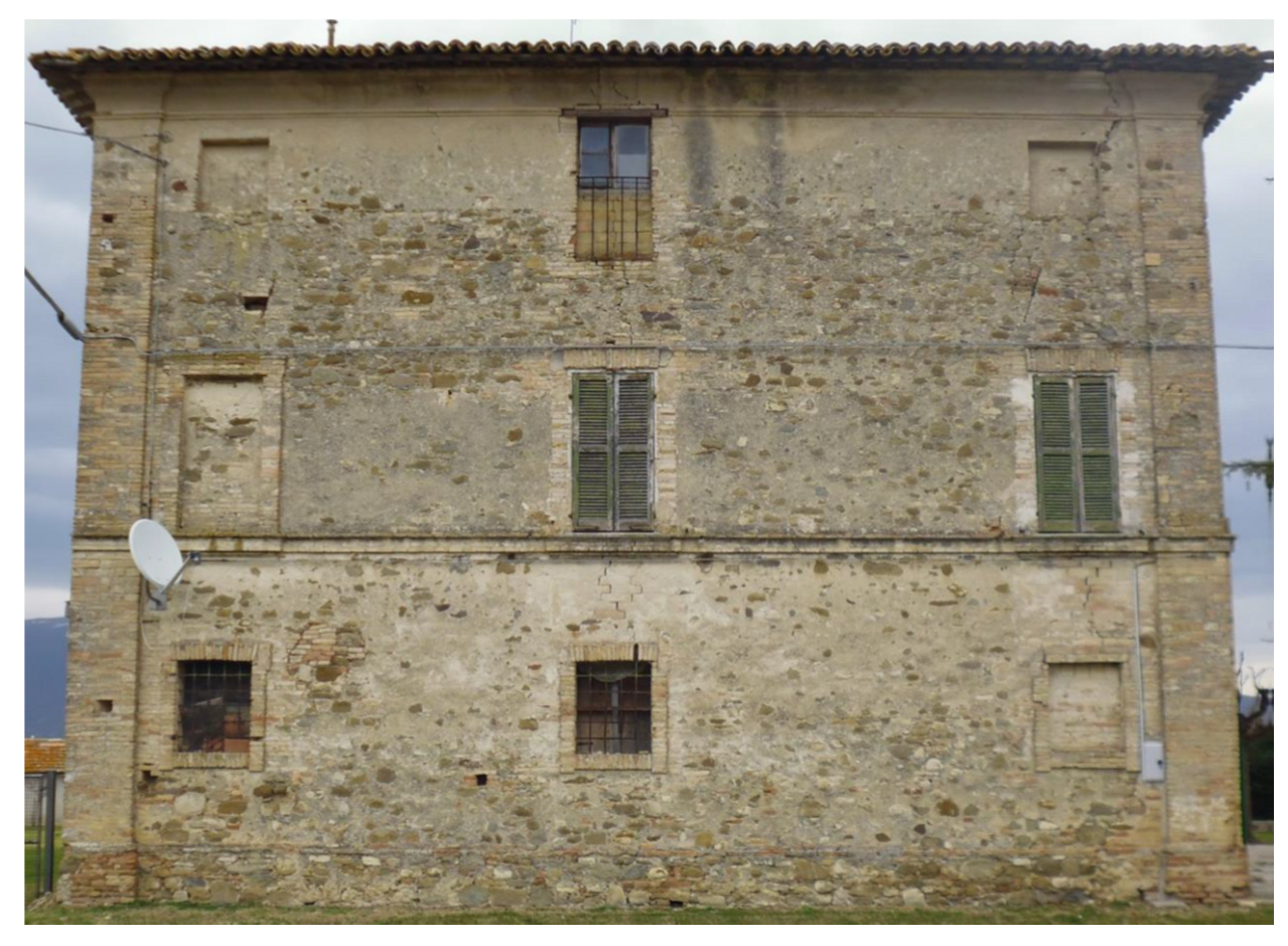
2. Description of the Building

The analyzed building was constructed around the 1600s in Perugia, and it is characterized by a rectangular plan with dimensions 20.65 m × 13.15 m (Figure 1). The construction presents three floors above ground and is made of uncoursed squared rubble masonry (Figure 2) whose mechanical properties, evaluated according to [25,26], are summarized in Table 1, where γ is the unit weight, E is Young’s modulus, G is the shear modulus, fm is the mean compressive strength and τ0 is the mean shear strength. The masonry walls of the building are characterized by a thickness equal to 45 cm.
The one-way slabs of the first and second floor (Figure 3) and the roof (Figure 4) are made of wooden structure.
As mentioned before, post-earthquake survey was performed after the 24th August 2016 Centro Italia seismic event. Different crack patterns have been observed in correspondence to the vertical and horizontal structural elements. In particular, the presence of diagonal cracks was detected in the masonry walls due to the shear forces acting on the walls during the earthquake and the low value of tensile strength which characterizes the masonry. The beginning of the activation of out-of-plane mechanisms of the façades produced by the structural behavior of the roof has been observed due to absence of tie-beams. Other cracks have been developed in correspondence to the openings and the lintels. Furthermore, the wooden slabs showed an excessive vertical deformation.

3. Numerical Analysis

3.1. Current Configuration

To evaluate the seismic behavior of the building, linear and non-linear analyses have been performed. In particular, non-linear static analysis has been carried out using the equivalent frame method [18,27] which represents a suitable approach for buildings characterized by a regular distribution of openings such as the one here analyzed (Figure 5b). The piers and the spandrels have been implemented through deformable beam elements interconnected by rigid offsets at their intersection. This modeling hypothesis is derived from the damages observed in this type of construction subjected to seismic event which show that, usually, cracks and failure modes are localized in piers and spandrels, while little damage is observed at their intersection, thus justifying the adoption of rigid offsets in the modelling process. Bending moments between orthogonal walls have been released to represent the unperfect toothing and avoid out-of-plane response of piers [28]. According to [26], the following collapse mechanisms have been considered for the structural elements: (i) diagonal shear cracking, (ii) sliding failure and (iii) rocking failure due to bending moment. Considering that the damage is assumed to be concentrated in localized sections of the building (in particular, in the mid and at the end of the monitored elements), non-linear beams with lumped inelasticity are used for piers and spandrels. The lumped inelasticity was modeled in the EFM with non-linear flexural or shear springs obtained considering, respectively, moment-rotation or shear-displacement laws. Hinges are characterized by an elastic perfectly plastic behavior where the ultimate displacement capacity, obtained considering the limit drift calculated as reported in [25], is taken equal to 0.6% for the flexural hinge and 0.4% for the shear hinge. The sectional limit strength was calculated by the finite element software considering the masonry mechanical characteristics listed in Table 1 and the actual stress distribution.
Two horizontal load profiles have been considered to perform the pushover analysis, representing the inertia forces related to the occurrence of a seismic event: (i) acceleration distribution proportional to the first mode and (ii) uniform acceleration distribution. The different horizontal load profiles have been applied in both X and Y direction, considering both positive and negative signs. Figure 6 shows the capacity curves for X (red curves) and Y (green curves) directions obtained from the execution of the pushover analysis.
To evaluate the seismic vulnerability of the structure, N2 method [29] has been used considering the seismic action defined according to [25], where the fundamental parameters are listed in Table 2.
The seismic capacity of the structure was defined considering two different types of seismic vulnerability risk indices (RI) obtained as the ratio between the peak ground acceleration which leads to the collapse of the structure (PGAC), the design peak ground acceleration reported in Table 3 (PGAD), and the related return periods (RPC and RPD):
RIPGA = PGAC/PGAD,
RIRP = RPC/RPD.
Table 3 shows the minimum risk index values obtained considering the capacity curves calculated using the above-mentioned different horizontal load profiles, both in terms of peak ground acceleration and related return period.
It is possible to notice that the minimum value of risk index calculated is less than one, which characterizes a structure with a high vulnerability to the seismic action.
Furthermore, with the N2 method, the behavior factor (q) that characterized the structure has been calculated and is equal to q = 2.
As mentioned in previous Section 1, kinematic analysis has been carried out in order to analyze the local collapse mechanisms considering the different perimeter walls of the building (Figure 7).
Table 4 summarizes the results expressed in terms of risk indices for each local collapse mechanism analyzed, where PGACLM represents the peak ground acceleration that activates the local mechanism and RPCLM represents the related return period.
The results show that the risk indices obtained are less than one both in terms of peak ground acceleration and return period for each local collapse mechanism considered, confirming the evident seismic vulnerability which characterizes the structure.

3.2. Retrofitted Configuration: Intervention on Masonry Walls

To mitigate the seismic vulnerability of the building, different retrofitting interventions have been proposed. Reinforced plaster layer and cement-based grout injections have been applied in each masonry wall of the building in order to improve their horizontal load-bearing capacity [30]. Table 5 shows the mechanical properties of the masonry considered after the execution of the retrofitting interventions.
An additional wall (45 cm thick) made in Poroton blocks and M10 cement mortar has been built adjacent to the central stairwell (Figure 8).
To avoid the activation of local collapse mechanisms, a concrete curb adjacent to the roof has been realized and the interlocking between orthogonal masonry walls has been improved through the application of steel ties. Furthermore, the wooden slabs have been reinforced with the construction of new wood–concrete slabs connected to the existing structural elements by means of shear connectors to improve the box behavior of the building, realizing a rigid diaphragm at each floor (Figure 9).
Equivalent frame model representing the retrofitted configuration has been implemented considering the same hypotheses used for the equivalent frame model implementation of the current configuration (Figure 10).
Pushover analysis has been carried out considering the same horizontal load profiles used for the evaluation of the seismic behavior of the current configuration. Figure 11 shows the capacity curves obtained for X (red curves) and Y (green curves) direction considering the retrofitted configuration.
Table 6 summarizes the results of the non-linear static analysis performed for the retrofitted configuration in terms of minimum value of risk indices calculated considering the different capacity curves shown in Figure 11.
It is possible to notice that the minimum value of the risk indices obtained by the execution of the pushover analysis, both in terms of peak ground acceleration and return period, is greater than one. It is important to highlight that the 2475 year-mark (which corresponds to a value of peak ground acceleration equal to 0.427 g for the area where the case study is built) represents the maximum return period that can be considered for the evaluation of the seismic vulnerability of this type of construction according to what is reported in [25,26]. In addition, for the retrofitted configuration, the activation of the local collapse mechanisms has been evaluated through the kinematic approach. Figure 12 shows the possible local collapse mechanisms that can occur for the retrofitted configuration while Table 7 summarizes the related results obtained expressed in terms of the same risk indices.
The obtained results show that for all local collapse mechanisms analyzed, the risk indices reach the maximum considered values defined according to what is reported in [25,26].

3.3. Retrofitted Configuration: Intervention on the Roof Structure

In addition to the retrofitting interventions described above concerning the improvement of the load-bearing capacity of the masonry walls and the realization of the connection between orthogonal walls and the diaphragm floors, in view of the need to replace the roof, seriously damaged during the 2016 Centro Italia earthquake, a cross-laminated roof solution has been proposed. In particular, a new cross-laminated roof characterized by a thickness equal to 14 cm (composed by seven layers each, 2 cm thick) has been realized.
To evaluate the effects of the cross-laminated roof on the seismic behavior of the retrofitted configuration of the building, a 3D Finite Element model has been implemented using a commercial software [31], where the masonry walls have been modelled with solid elements (Figure 13). The presence of the reinforced slabs has been considered through the introduction of rigid diaphragms in correspondence to each floor.
The cross-laminated panels are represented by bidimensional elements, whereas the panel-to-panel and wall-to-panel connections are introduced by inelastic springs (Figure 14) [32]. Table 8 summarizes the mechanical properties of the cross-laminated panel considering its orthotropic behavior.
The hysteretic behavior of the connections has been defined according to what is reported in [33] (Figure 15) based on Clough constitutive model [34] and considering cylindrical connectors with a diameter equal to 10 mm and elastic stiffness 6200 N/mm.
A non-linear time history analysis considering Rayleigh damping has been performed using the seven spectrum-compatible accelerograms reported in Figure 16, obtained using REXEL software [35] by considering the site seismic parameters listed in Table 2.
Starting from the masonry mechanical properties reported in Table 5, a Concrete Damage Plasticity (CDP) constitutive law has been adopted considering the fundamental parameter listed in Table 9, where ψ is the dilation angle, e is the dimensionless eccentricity, fbo/fco is the ratio of biaxial compressive to uniaxial compressive yield stress, Kc is the coefficient determining the shape of the deviatoric cross-section, and v is the viscosity parameter [36].
Figure 17 shows the results in terms of X and Y displacement histories comparing the cross-laminated roof structure with a classic wood roof solution (with 4 cm-thick single planks). The results show the displacements of the roof for the first 25 s of the time history analysis representing the most significant part of the seismic events. The trends shown in Figure 17 represent the average value among the seven spectrum-compatible accelerograms combined according to what is reported in [25].
The results show an important decrease in the displacements in both directions. The maximum displacement in X direction is about 2.5 cm in comparison to that (about 9 cm) obtained by the single plank roof structure. In addition, in Y direction, the reduction is significant because the maximum displacement is about 1.8 cm in comparison to the value (about 5.8 cm) obtained with the single plank solution. The displacement reduction is due to the dissipation of the energy occurring in the inelastic springs.

4. Conclusions

The paper focused on the structural rehabilitation of an historical masonry building hit by the strong 2016 Centro Italia seismic event. Starting from the post-earthquake survey, 3D finite element models of the current configuration have been implemented using an equivalent frame approach in order to evaluate the seismic vulnerability of the building. Moreover, a kinematic analysis has been performed to detect the possible activation of the local collapse mechanisms. The results have shown that the building was afflicted by a high vulnerability under seismic action. Therefore, different retrofitting interventions have been studied to improve the seismic response of the construction. In particular, reinforced plaster layer and cement-based grout injections have been applied in each masonry wall of the building in order to improve their horizontal load-bearing capacity. An additional Poroton blocks wall adjacent to the central stairwell has been also introduced for improving the stiffness redistribution of the seismic resistant structural elements. To avoid the activation of local collapse mechanisms, a concrete curb adjacent to the roof has been introduced and the interlocking between orthogonal masonry walls has been improved through the application of steel ties. Furthermore, the wooden slabs have been substituted by wood–concrete slabs with shear connectors to pursue the box behavior of the building. These retrofitting techniques permitted to achieve the seismic performance required by [25].
Two possible configurations of roof structure have been studied by retaining wooden-based technologies: traditional single planks and cross-laminated panels. The comparison between the two solutions was carried out by implementing 3D finite element model and by introducing the seismic event as seven spectrum-compatible accelerograms. The results were analyzed in terms of roof displacements. The cross-laminated panel solution allowed to reduce the displacements by the energy dissipations of the panel-to-panel and wall-to-panel connections represented by inelastic springs in the model.
Finally, it is important to highlight that the retrofitting interventions used in the case study considered in this work can be applied to other buildings in similar conditions.

Author Contributions

Conceptualization, N.L. and M.Z.; methodology, E.R.; validation, A.C.; formal analysis, M.Z.; investigation, N.L.; editing, E.R.; supervision, A.C. All authors have read and agreed to the published version of the manuscript.

Funding

This research received no external funding.

Institutional Review Board Statement

Not applicable.

Informed Consent Statement

Not applicable.

Data Availability Statement

Not applicable.

Conflicts of Interest

The authors declare no conflict of interest.

References

  1. Brandonisio, G.; Lucibello, G.; Mele, E.; De Luca, A. Damage and performance evaluation of masonry churches in the 2009 L’Aquila earthquake. Eng. Fail. Anal. 2013, 34, 693–714. [Google Scholar] [CrossRef]
  2. De Matteis, G.; Criber, E.; Brando, G. Damage probability matrices for three-nave masonry churches in Abruzzi after the 2009 L’Aquila earthquake. Int. J. Archit. Herit. 2016, 10, 120–145. [Google Scholar]
  3. Gattulli, V.; Antonacci, E.; Vestroni, F. Field observations and failure analysis of the Basilica S. Maria di Collemaggio after the 2009 L’Aquila earthquake. Eng. Fail. Anal. 2013, 34, 715–734. [Google Scholar] [CrossRef]
  4. Acito, M.; Bocciarelli, M.; Chesi, C.; Milani, G. Collapse of the clock tower in Finale Emilia after the May 2012 Emilia-Romagna earthquake sequence: Numerical insight. Eng. Struct. 2014, 72, 70–91. [Google Scholar] [CrossRef]
  5. Jain, A.; Acito, M.; Chesi, C. Seismic sequence of 2016–2017: Linear and non-linear interpretation models for evolution of damage in San Francesco church, Centro Italia. Eng. Struct. 2020, 211, 110418. [Google Scholar] [CrossRef]
  6. Clementi, F.; Milani, G.; Ferrante, A.; Valente, M.; Lenci, S. Crumbling of amatrice clock tower during 2016 central italy seismic sequence: Advanced numerical insights. Frat. Ed Integrita Strutt. 2020, 14, 313–335. [Google Scholar] [CrossRef] [Green Version]
  7. Del Gaudio, C.; Di Domenico, M.; Ricci, P.; Verderame, G.M. Preliminary prediction of damage to residential buildings following the 21st August 2017 Ischia earthquake. Bull. Earthq. Eng. 2018, 16, 4607–4637. [Google Scholar] [CrossRef]
  8. Formisano, A.; Milani, G. Seismic vulnerability analysis and retrofitting of the SS. Rosario church bell tower in Finale Emilia (Modena, Italy). Front. Built Environ. 2019, 5, 70. [Google Scholar] [CrossRef]
  9. Priestley, M.J.N.; Seible, F. Design of seismic retrofit measures for concrete and masonry structures. Constr. Build. Mater. 1995, 9, 365–377. [Google Scholar] [CrossRef]
  10. Cao, X.Y.; Feng, D.C.; Wang, Z.; Wu, G. Parametric investigation of the assembled bolt-connected buckling-restrained brace and performance evaluation of its application into structural retrofit. J. Build. Eng. 2022, 48, 103988. [Google Scholar] [CrossRef]
  11. Pampanin, S.; Christopoulos, C.; Chen, T.H. Development and validation of a metallic haunch seismic retrofit solution for existing under-designed RC frame buildings. Earthq. Eng. Struct. Dyn. 2006, 35, 1739–1766. [Google Scholar] [CrossRef]
  12. Cao, X.Y.; Shen, D.; Feng, D.C.; Wang, C.L.; Qu, Z.; Wu, G. Seismic retrofitting of existing frame buildings through externally attached sub-structures: State of the art review and future perspectives. J. Build. Eng. 2022, 57, 104904. [Google Scholar] [CrossRef]
  13. D’Altri, A.M.; Sarhosis, V.; Milani, G.; Rots, J.; Cattari, S.; Lagomarsino, S.; Sacco, E.; Tralli, A.; Castellazzi, G.; de Miranda, S. Modeling strategies for the computational analysis of unreinforced masonry structures: Review and classification. Arch. Comput. Methods Eng. 2020, 27, 1153–1185. [Google Scholar] [CrossRef]
  14. Sacco, E.; Addessi, D.; Sab, K. New trends in mechanics of masonry. Meccanica 2018, 53, 1565–1569. [Google Scholar] [CrossRef] [Green Version]
  15. Masciotta, M.G.; Lourenço, P.B. Seismic analysis of slender monumental structures: Current strategies and challenges. Appl. Sci. 2022, 12, 7340. [Google Scholar] [CrossRef]
  16. Valente, M.; Milani, G.; Grande, E.; Formisano, A. Historical masonry building aggregates: Advanced numerical insight for an effective seismic assessment on two row housing compounds. Eng. Struct. 2019, 190, 360–379. [Google Scholar] [CrossRef]
  17. Tomazevic, M. The Computer Program POR; Report ZRMK; ZRMK: Ljubljana, Slovenia, 1978. (In Slovenian) [Google Scholar]
  18. Lagomarsino, S.; Penna, A.; Galasco, A.; Cattari, S. TREMURI program: An equivalent frame model for the nonlinear seismic analysis of masonry buildings. Eng. Struct. 2013, 56, 1787–1799. [Google Scholar] [CrossRef]
  19. Roca, P.; Cervera, M.; Gariup, G.; Pelà, L. Structural analysis of masonry historical constructions. classical and advanced approaches. Arch. Comput. Methods Eng. 2010, 17, 299–325. [Google Scholar] [CrossRef] [Green Version]
  20. Quagliarini, E.; Maracchini, G.; Clementi, F. Uses and limits of the Equivalent Frame Model on existing unreinforced masonry buildings for assessing their seismic risk: A review. J. Build. Eng. 2017, 10, 166–182. [Google Scholar] [CrossRef]
  21. Sansoni, C.; da Silva, L.C.M.; Marques, R.; Pampanin, S.; Lourenço, P.B. SLaMA-URM method for the seismic vulnerability assessment of UnReinforced Masonry structures: Formulation and validation for a substructure. J. Build. Eng. 2022, 63, 105487. [Google Scholar]
  22. Brando, G.; Pagliaroli, A.; Cocco, G.; Di Buccio, F. Site effects and damage scenarios: The case study of two historic centers following the 2016 central italy earthquake. Eng. Geol. 2020, 272, 105647. [Google Scholar] [CrossRef]
  23. Garofano, A.; Lestuzzi, P. Seismic assessment of a historical masonry building in Switzerland: The “Ancien Hôpital De Sion”. Int. J. Archit. Herit. 2016, 10, 975–992. [Google Scholar] [CrossRef]
  24. Griffith, M.C.; Magenes, G.; Melis, G.; Picchi, L. Evaluation of out-of-plane stability of unreinforced masonry walls subjected to seismic excitation. J. Earthq. Eng. 2003, 7, 141–169. [Google Scholar] [CrossRef]
  25. Ministero delle Infrastrutture e dei trasporti. Nuove Norme Tecniche per le Costruzioni—Decreto Ministeriale del 17/01/2018; NTC2018—Italian Design Building Code, only in Italian; Ministero delle Infrastrutture e dei trasporti: Rome, Italy, 2018. [Google Scholar]
  26. Ministero delle Infrastrutture e dei trasporti. Istruzioni per l’applicazione delle Nuove Norme Tecniche per le Costruzioni di cui al decreto ministeriale 17/01/2018; Circolare n. 7 del 21/01/2019; Commentary to the Italian Design Building Code, only in Italian; Ministero delle Infrastrutture e dei trasporti: Rome, Italy, 2019. [Google Scholar]
  27. Magenes, G. A method for pushover analysis in seismic assessment of masonry buildings. In Proceedings of the 12th World Conference on Earthquake Engineering, Auckland, New Zealand, 30 January–4 February 2000. [Google Scholar]
  28. Scamardo, M.A.; Crespi, P.; Longarini, N.; Zucca, M. Seismic vulnerability and retrofitting of a historical masonry building. In Proceedings of the REHABEND Construction Pathology, Rehabilitation Technology and Heritage Management, Granada, Spain, 13–16 September 2022. [Google Scholar]
  29. Fajfar, P.; Gaspersic, P. The N2 method for the seismic damage analysis of RC buildings. Earthq. Eng. Struct. Dyn. 1996, 25, 31–46. [Google Scholar] [CrossRef]
  30. Vintzileou, E.; Tassios, T.P. Three-leaf stone masonry strengthened by injecting cement grouts. ASCE J. Struct. Eng. 1995, 121, 848–856. [Google Scholar] [CrossRef]
  31. MIDAS FEA Analysis Reference. 2021. Available online: https://www.midasoft.com/bridge-library/civil/products/midasfeanx (accessed on 1 January 2021).
  32. Dauda, J.A.; Silva, L.C.; Lourenço, P.B.; Iuorio, O. Out-of-plane loaded masonry walls retrofitted with oriented strand boards: Numerical analysis and influencing parameters. Eng. Struct. 2021, 243, 112683. [Google Scholar] [CrossRef]
  33. Gavric, I.; Fragiacomo, M.; Ceccotti, A. Cyclic behaviour of typical metal connectors for cross-laminated (CLT) structures. Mater. Struct. 2015, 48, 1841–1857. [Google Scholar] [CrossRef]
  34. Clough, W. Effect of Stiffness Degradation on Earthquake Ductility Requirements, 1st ed.; Structural Engineering Laboratory, University of California: Berkeley, CA, USA, 1996; pp. 1–134. [Google Scholar]
  35. Iervolino, I.; Galasso, C.; Cosenza, E. REXEL: Computer aided record selection for code-based seismic structural analysis. Bull. Earthq. Eng. 2010, 8, 339–362. [Google Scholar] [CrossRef]
  36. Poiani, M.; Gazzani, V.; Clementi, F.; Milani, G.; Valente, M.; Lenci, S. Iconic crumbling of the clock tower in Centro Italia after 2016 central Italy seismic sequence: Advanced numerical insight. Procedia Struct. Integr. 2018, 11, 314–321. [Google Scholar] [CrossRef]
Figure 1. The analyzed building: side elevation and typical plan.
Applsci 12 11789 g001aApplsci 12 11789 g001b
Figure 2. (a) Detail of the masonry walls of the building; (b) Masonry texture (inspection window dimension 40 × 40 cm).
Applsci 12 11789 g002
Figure 3. First and second floor slab (unit of measure is cm).
Applsci 12 11789 g003
Figure 4. Roof (unit of measure is cm).
Applsci 12 11789 g004
Figure 5. (a) 3D Finite Element model of the building; (b) Equivalent frame model.
Applsci 12 11789 g005
Figure 6. Capacity curves (current configuration).
Applsci 12 11789 g006
Figure 7. Local collapse mechanisms.
Applsci 12 11789 g007aApplsci 12 11789 g007b
Figure 8. The new wall made in Poroton blocks and M10 cement mortar.
Applsci 12 11789 g008
Figure 9. Retrofitted configuration of the wooden slabs (unit of measure in cm).
Applsci 12 11789 g009
Figure 10. (a) 3D Finite Element model of the building (retrofitted configuration); (b) Equivalent frame model (retrofitted configuration).
Applsci 12 11789 g010
Figure 11. Capacity curves (retrofitted configuration).
Applsci 12 11789 g011
Figure 12. Local collapse mechanisms for the retrofitted configuration.
Applsci 12 11789 g012aApplsci 12 11789 g012b
Figure 13. (a) Finite element model implemented using MIDAS FEA software; (b) Mesh.
Applsci 12 11789 g013
Figure 14. Modeling of the panel–panel and panel–curb connections.
Applsci 12 11789 g014
Figure 15. Connection hysteretic behavior.
Applsci 12 11789 g015
Figure 16. Seismic records.
Applsci 12 11789 g016aApplsci 12 11789 g016bApplsci 12 11789 g016c
Figure 17. Comparison between the obtained maximum displacements of the roofs in X and Y direction considering the cross-laminated roof structure (14 cm thickness) and a single plank wooden roof (4 cm thickness).
Applsci 12 11789 g017
Table 1. Mechanical properties of the masonry.
γ
[kN/m3]
E
[MPa]
G
[MPa]
fm
[MPa]
τ0
[MPa]
2012304102.000.035
Table 2. Seismic parameters.
Limit StateSLV
Life of the structure (VN)[year]50
Use category[-]II
Coefficient for use category (Cu)[-]1
Reference life (VR)[year]50
Topographic coefficient (ST)[-]1
Soil category[-]C
Design ground acceleration (ag)[g]0.299
Probability of exceedance (PVR)[%]10
Table 3. Risk indices obtained from pushover analysis (current configuration).
PGACPGADRIPGARPCRPDRIRP
[g][g][-][year][year][-]
0.0470.2990.15764750.013
Table 4. Risk indices calculated for the different local collapse mechanisms (current configuration).
MechanismPGACLMPGADRIPGARPCLMRPDRIRP
[n°][g][g][-][year][year][-]
10.1180.2990.395414750.086
20.1410.2990.472584750.122
30.2210.2990.7401694750.356
40.1000.2990.335284750.059
50.1350.2990.452534750.112
60.2190.2990.7331664750.349
70.1650.2990.553834750.175
80.2430.2990.8142294750.482
Table 5. Mechanical properties of the masonry after the retrofitting interventions.
γ
[kN/m3]
E
[MPa]
G
[MPa]
fm
[MPa]
τ0
[MPa]
2020916973.400.06
Table 6. Risk indices obtained from pushover analysis (retrofitted configuration).
PGACPGADRIPGARPCRPDRIRP
[g][g][-][year][year][-]
0.4270.2991.42824754755.211
Table 7. Risk indices calculated for the different local collapse mechanisms (retrofitted configuration).
MechanismPGACLMPGADRIPGARPCLMRPDRIRP
[n°][g][g][-][year][year][-]
10.4270.2991.43024754755.211
20.4270.2991.43024754755.211
30.4270.2991.43024754755.211
40.4270.2991.43024754755.211
50.4270.2991.43024754755.211
60.4270.2991.43024754755.211
70.4270.2991.43024754755.211
80.4270.2991.43024754755.211
90.4270.2991.43024754755.211
100.4270.2991.43024754755.211
110.4270.2991.43024754755.211
Table 8. Mechanical properties of the cross-laminated panel.
γ
[kN/m3]
Ex
[MPa]
Ey
[MPa]
Ez
[MPa]
570595387370
G
[MPa]
νxy
[-]
νxz
[-]
νyz
[-]
6900.45000.01380.0138
Table 9. Concrete Damage Plasticity parameters used in this work.
ψ
[°]
e
[-]
fbo/fco
[-]
Kc
[-]
v
[-]
100.1001.1600.6670
Publisher’s Note: MDPI stays neutral with regard to jurisdictional claims in published maps and institutional affiliations.

