Article

Failure Analysis of Gantry Crane Slewing Bearing Based on Gear Position Accuracy Error

1
School of Transportation and Logistics Engineering, Wuhan University of Technology, Wuhan 430063, China
2
School of Computer Science and Artificial Intelligence, Wuhan University of Technology, Wuhan 430070, China
3
China Railway Construction Heavy Industry Corporation Limited, Changsha 410100, China
4
School of Art and Design, Wuhan University of Technology, Wuhan 430070, China
*
Author to whom correspondence should be addressed.
Appl. Sci. 2022, 12(23), 11907; https://doi.org/10.3390/app122311907
Submission received: 24 October 2022 / Revised: 16 November 2022 / Accepted: 18 November 2022 / Published: 22 November 2022
(This article belongs to the Special Issue New Frontiers in Advanced Manufacturing)

Abstract

:
In large ports, shipyards, and other places of handling operations, gantry cranes are widely used. As a typical slewing crane, its slewing-bearing large gear ring is prone to tooth breakage problems due to the existence of long-term complex alternating load. This paper presents a new fault analysis method based on the gear position accuracy error. Firstly, the relative displacement relationship between the pinion and large gear ring and the large gear ring gear teeth stress nature were analyzed through the establishment of the rotary table structure, slewing bearing, and cylinder structure assembly finite element model. In addition, a dynamic data acquisition instrument and resistance strain gauge data were separately applied to analyze the pinion and large gear ring displacement along with cylinder structure stress for the test position accuracy error. The final results show that under the frontal load condition, the horizontal displacement deviation of the pinion gear and the large gear ring is approximately 2.9 mm, which leads to an increase of 23% in the stress value of the upper tooth root at the engagement of the large gear ring, causing extrusion and accelerating the fatigue and even fracture of the gear teeth.

1. Introduction

With the continuous advancement of global integration and the rapid development of international trade, port transportation has increased dramatically. In large ports, shipyards, and other places of handling operations, gantry cranes are widely used. Large bearing gantries are particularly common due to their advantages of fewer components, novel structure, and a small tail diameter of the rotary part. At present, as the main power component of large portal cranes’ slewing bearing, its large gear ring gear has a high probability of teeth breaking as a consequence of tooth root crack, which seriously affects the service life of portal cranes and reduces port transportation efficiency. Therefore, analyzing the causes of broken teeth of gantry crane slewing ring gears is important.
The rotary movement of gantry cranes mainly relies on the rotary mechanism. The mechanism contains two parts: The slewing drive and the slewing support device. The driving force of the gantry crane’s slewing action is mainly provided by the slewing drive [1,2]. The slewing support device is used to connect the slewing and non-slewing parts of the gantry crane, providing support and restraint to ensure the neutrality of the two parts [3,4,5,6]. The slewing support device is used to connect the slewing and non-slewing parts of the gantry crane, providing support and restraint to ensure the alignment of the two parts.
In this study, through the research on gantry cranes in Caofeidian, Lianyungang, Rizhao, and other large Chinese ports, it is found that the gantry crane’s slewing ring gear teeth generally have tooth root cracks and broken teeth, and the average rate of broken teeth of each port gantry crane’s slewing bearing is more than 30%.
Regarding the broken teeth of the slewing bearing, Zhang Bing [7] established a gear tooth calculation model for the slewing mechanism when braking and stopping. The dynamic response characteristics of gears were analyzed according to different slewing speeds. It follows that tooth surface pitting and tooth breakage are basically caused by large impacts. Ding Bingyi [8] analyzed the causes of the broken slewing gear of a port gate machine and pointed out that the load condition of the slewing gear and driving pinion are influenced by the side clearance of gear teeth. The corresponding broken gear repair plan was put forward as a consequence. Yang Yugang [9] analyzed the factors that caused the broken gears of gantry cranes’ slewing bearing such as tooth side clearance, gear tooth lubrication, and crane operation normality. Zhu Kunjian and Guo Shiying [10] focused on the GQI-5 crane that has been in overload operation for a long time. The two gear teeth of its slewing bearing were determined to have broken from the root of the teeth, and a repair process combining welding and implantation of gear teeth was proposed. Existing research on the broken teeth of gantry cranes’ slewing ring mainly focuses on impact, crane operation specifications, and other factors that lead to breaking. There is no research on the position accuracy error of the large gear ring and pinion of gantry cranes after lifting. However, this position accuracy error, which further leads to tooth breakage, will have a significant influence on the analysis of slewing ring dynamics.
In this paper, a new fault analysis method based on the gear position accuracy error is proposed. Firstly, through the finite element analysis method, the displacement and force nature of the pinion and the large gear ring before and after the assembly of the slewing bearing model and slewing structure are studied, and the cause of a large gear ring broken tooth fault is initially proposed. Secondly, the dynamic data acquisition instrument is used to conduct displacement tests on the driving pinion and the large gear ring of the slewing bearing, and the test results are compared with the finite element calculation results to verify the reasonableness of the results. Finally, the influence of the displacement deviation of the pinion and large gear ring on the gear tooth fracture problem was explained.

2. Slewing Bearing Mechanical Analysis and Test

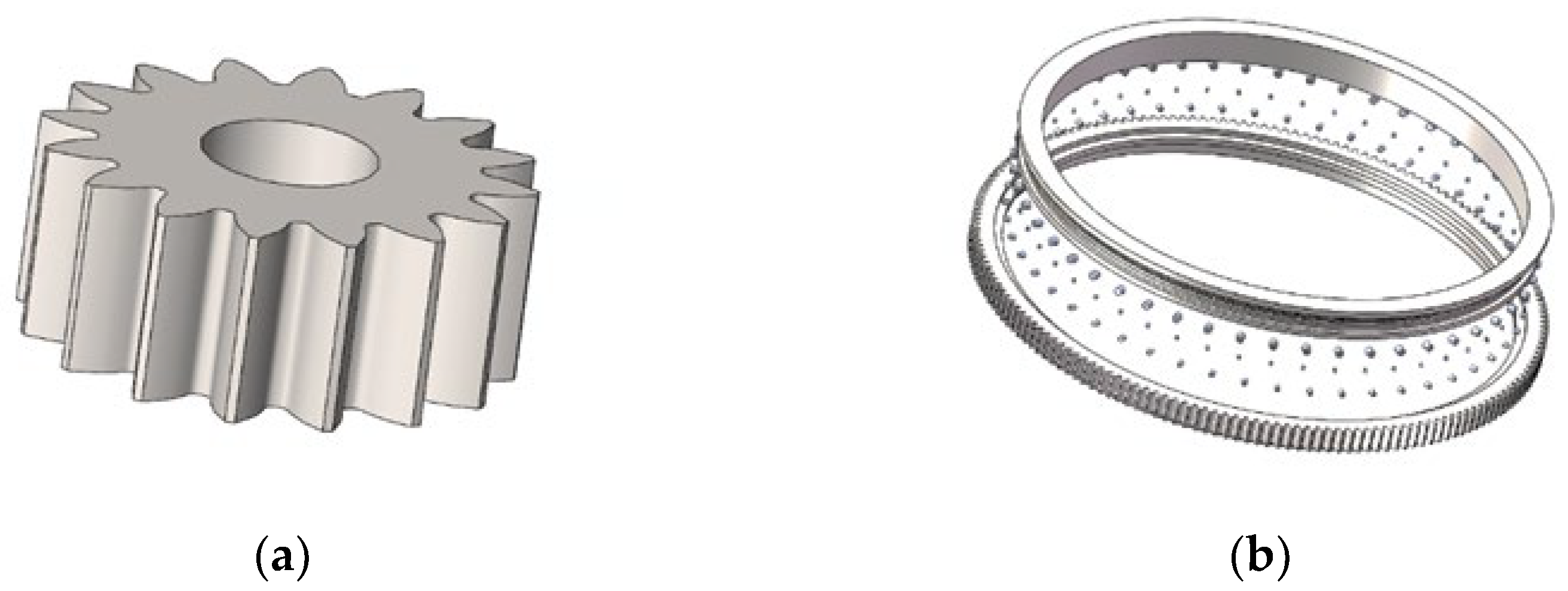
2.1. Model Construction

Due to the large size of the three-row roller slewing bearing of the MQ4038 port gantry crane and the large number of internal structural contact parts, larger computational resources are required. Therefore, according to the actual loading characteristics of the slewing bearing, reasonable assumptions and simplifications are made to the model on the basis of less influence on the analysis process [11,12]:
  • Disregarding the influence of components such as cages, seals, retaining bolts, etc., on the analysis process.
  • Ignoring chamfers, excessive rounding, and some step structures that have less influence on the analysis process [13,14,15].
  • Assuming the pinion is rigidly connected to the turntable structure and ignoring the influence of components in the slewing mechanism.
  • Accessories such as stairs and cabs are ignored in the modeling because they have less influence on the main structural forces.
Referring to the design parameters of the gantry crane, slewing bearing structure parameters. and design drawings, we established the 3D models of the gantry crane turntable structure, slewing bearing, and cylinder structure, which are shown in Figure 1, Figure 2 and Figure 3. All of the components are assembled in Solidworks according to the actual matching position relationship.
In order for FEM software to correctly identify the assembly model, the assembly model needs to be pre-processed to ensure the integrity of the model and the correctness of the fit relationship. The Simulation module in Solid works is a finite element analysis module, which can pre-process a 3D model to ensure the correctness of the model after it is imported into ANSYS Workbench. Otherwise, ANSYS Workbench will consume a great deal of computation time and computer memory resources for analysis, resulting in a lower analysis time of the assembly model and even causing problems such as non-convergence of the analysis results.
Due to the large overall size of the assembly and the limited functionality of the simulation analysis module compared to professional finite element software such as ANSYS Workbench, the assembly mesh can be divided in Simulation first in order to save analysis time and memory, and if the mesh can be reasonably divided, it means that the modeling can be successfully imported into ANSYS Workbench. Since there are many components in the model, it is difficult to mesh the whole assembly if the default meshing method is used, so a local mesh control method is used for meshing, so that each component is assigned different mesh sizes according to the needs. The schematic diagram of the grid after the division is shown in Figure 4.
Once the meshing is complete, it can be preliminarily judged that the assembled model essentially meets the analysis requirements, so the file is converted into X_T format for subsequent smooth import into ANSYS Workbench software.

2.2. Pre-Assembly Engagement Mechanical Properties

Based on the meshing relationship between the pinion and the large ring gear of the slewing ring, the assembly is completed in SolidWorks and then imported into ANSYS Workbench for analysis. Since the shape of the large ring gear structure of the pinion and the slewing bearing is more regular and there are more tooth surfaces, we considered using sweeping and curvature-based meshing methods. The minimum size of the overall mesh is 9 mm, the curvature coefficient is 0.5, and the mesh correlation value setting size is 30.
When defining the tooth contact pair in ANSYS Workbench, the surface-to-surface contact form is selected, in which the target surface selects the large ring gear surface. The contact surface selects the pinion surface. The frictional contact type is used. The contact coefficient is selected to be 0.15. The “Pure Penalty” (penalty function equation) is used to reasonably adjust the contact surface contact stiffness. Finally, we complete the definition of the gear contact pair. In the case of ideal gear meshing, the roller seat movement of the outer ring of the slewing ring is restricted, so when setting the boundary condition, the degrees of freedom in six directions of the raceway surface inside the large ring gear of the slewing ring are limited, and according to the parameters of the slewing mechanism of the MQ4038 gantry crane and the uniform contact of the tooth surface of the gear, a rated torque of 3.5 × 10⁷ N·mm is added to the pinion. The mashing results are shown in Figure 5.
After setting contact parameters and boundary conditions [9,10], the static analysis of the large gear ring is performed. The static analysis of the large gear ring is shown in Figure 6. The maximum stress at the root of the gear teeth is 208.8 MPa, which does not exceed the permissible stress. The stresses at the root of the gear teeth at the mesh are more uniform (red area), and the equivalent stresses at the root of the upper teeth and the root of the lower teeth are 205.08 MPa and 205.04 MPa, respectively, which are more consistent with the ideal mesh.

2.3. Gear Meshing Characteristics after Assembly

As the actual force situation of the gantry crane is more complicated, the slewing bearing will produce certain displacement in operation, which may have an impact on the parallelism of the gear axis, so the gear meshing relationship will be different from the ideal situation. Therefore, it is necessary to analyze the meshing relationship between the gear teeth and the nature of the force on the gear teeth after the assembly of the slewing bearing model with the turntable and cylinder structure and to compare the analysis with the ideal meshing situation.

2.3.1. Assembly Model Guidance and Grid Generation

The import of the assembly model is defined separately according to the material parameters and is shown in Figure 7. Since the assembly has many different parts and various structural forms, and the structure of most parts is basically a regular body, a combination of a hexahedral sweep mesh and a multi-zone mesh is used for the division.
After setting the mesh form, the overall minimum mesh size is set to 9 mm, the curvature coefficient is 0.5, and the mesh correlation value is set to size 30 for mesh partitioning, which generates 283,407 cells and 497,564 nodes. The grid division results are shown in Figure 8.

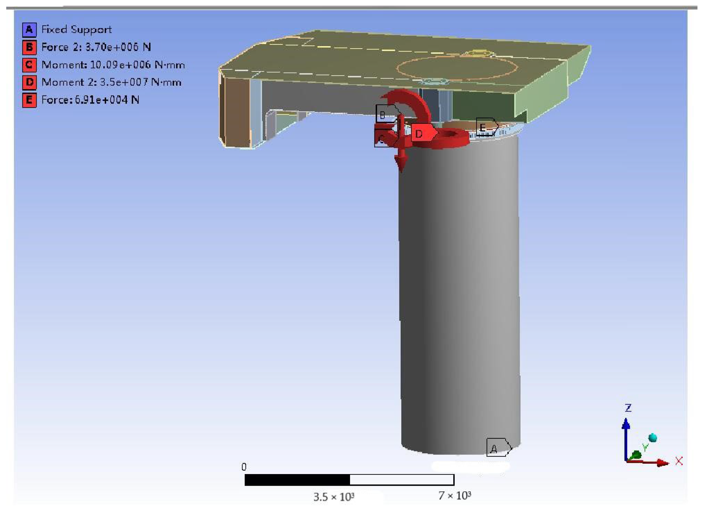
2.3.2. Definition of Contact Parameters and Boundary Conditions

According to the actual operation of the MQ4038 gantry crane, the contact part is first defined. The contact form still chooses “surface-face” contact, and the pinion and the large ring gear contact mode are set the same as before. Considering the roller contact, because the roller is convex, the contact surface selects three rows of roller surfaces, the target surface selects each roller seat surface, the setting of the contact parameters is basically the same as 2.2, and the rest of the components are set to the bound contact form and finally complete the definition of the contact pair. The axial load Fa, the radial load Fr, and the overturning moment M of the slewing bearing are calculated when the rated load (40 t) of the test gantry crane is lifted and located at the maximum amplitude (38 m).
  • Axial load calculation
Considering the additional dynamic load under inertia when the gantry crane lifts the rated load of 40 t, the dynamic load during lifting Q m is taken. The dynamic load is analyzed by the product of the dynamic load coefficient φ 2 and the lifting load Q :
Q m = φ 2 Q
φ 2 = φ 2 2 m i n
where φ 2 m i n is the minimum value of the hoisting dynamic load factor, β 2 is the factor set by the hoisting status level, and v is the steady hoisting speed (m/s).
The values of the coefficients φ 2 m i n and φ 2 m i n are shown in Table 1 and are divided into four levels.
The whole level of the gantry crane is A7, which belongs to the more frequent heavy load use type considering that its lifting state level is HC4. v takes the lifting mechanism speed at a rated load of 35 m/min, so according to Formulas (1) and (2), the lifting load Q m can be obtained:
Q m = 55.2   t
Since the gantry crane slewing structure self-weight F G = 321.94 t (refer to MQ4038 type swing part self-weight load), the magnitude of the axial load on the slewing bearing can be obtained:
F a = Q m + F G = 3.70   ×   10 6   N
2.
Radial Load Calculation
In the calculation of the radial load of the slewing bearing, the main consideration is the horizontal load generated by wind-induced cargo deflection, through the lifting weight and cargo deflection angle α calculated according to Formula (5).
T = Q · tan α
where T is the horizontal load from cargo deflection, Q is the lifting load, and α is the deflection angle.
Since the gear is mainly affected by the horizontal force in the direction of the boom when it is engaged, the deflection angle of the goods in the plane of the boom variation is considered. The deflection angle α is determined to be 10° according to the parameters of the gantry crane, and the deflection horizontal load is calculated via Formula (5). Therefore, the radial load on the slewing bearing Fr can be calculated:
Fr = T
3.
Calculation of overturning moment
Under the consideration of wind action, the total load of the slewing bearing is shown in Table 2.
According to the magnitude of each load calculated in Table 2, the slewing bearing structure was loaded into the assembly model. Axial load was added on the roller seat surface on the inner ring of the slewing ring. The radial load was added on the roller seat surface in the slewing bearing, and the load direction was the same as the direction of the cargo. The overturning moment was added to the roller seat surface on the inner ring of the slewing ring. Considering the driving force effect of the pinion on the slewing bearing, the rated torque of 3.5 × 10⁷ N-mm is added to the pinion. Since the root of the cylinder in the non-slewing part is welded to the gantry beam, the static analysis considers the root of the cylinder as fixed, and a fixed restraint is applied to the bottom of the cylinder. The specific load application and restraint situation are shown in Figure 9, where the boom variation plane is the XOZ plane, and the boom orientation is in the x-axis-positive direction.

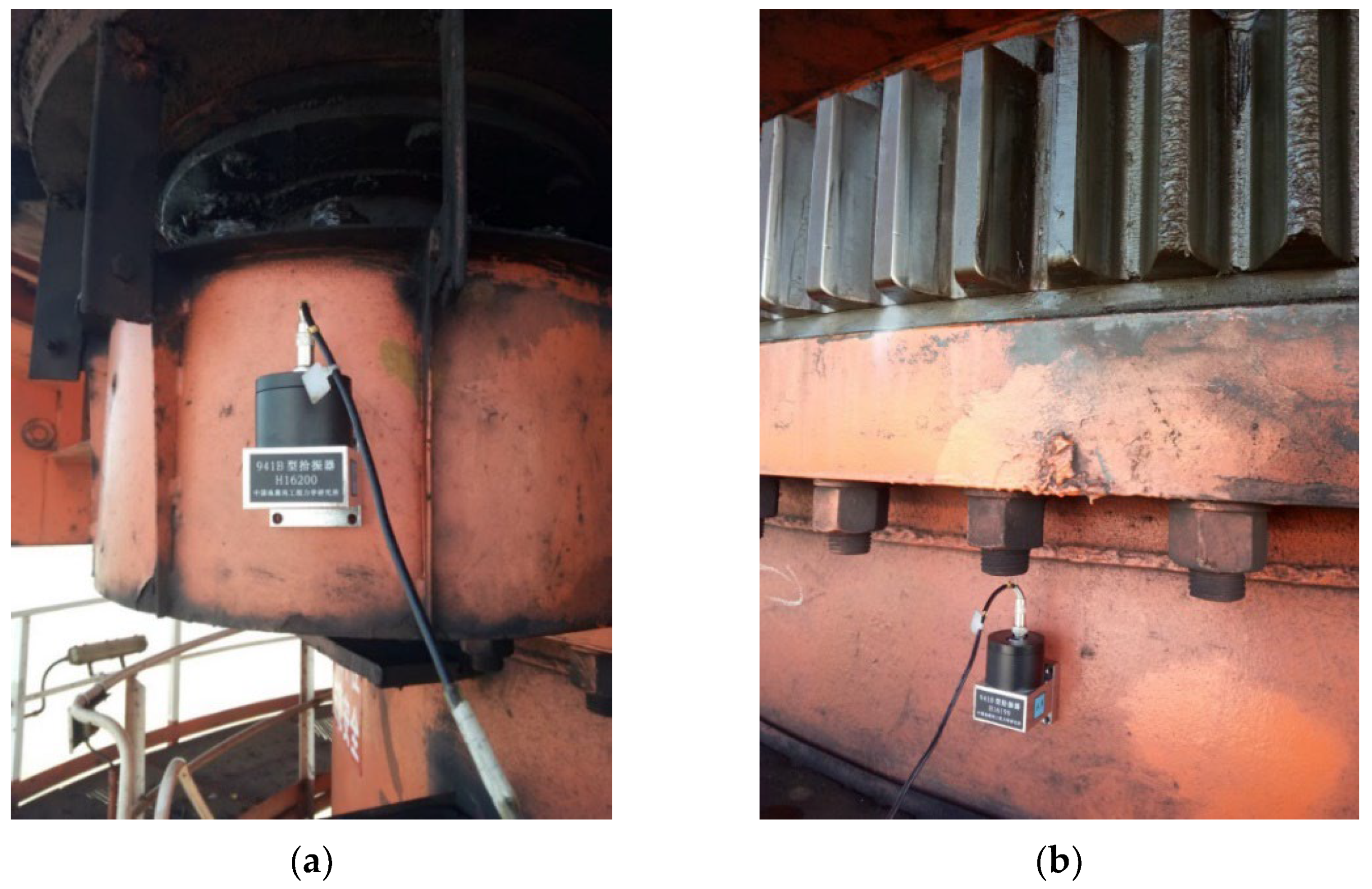
2.4. Test Bench Construction

In order to verify the reliability of the finite element model analysis results, the pinion and large gear ring displacement cases and cylinder stress cases were tested during the actual operation of the gantry crane [16,17,18]. The test results were compared with the finite element calculation results to verify the influence of the pinion and large gear ring gear tooth meshing relationship.
This research mainly adopts the D1000 general dynamic data acquisition instrument, together with the 941B type pickup, to conduct displacement tests on the gantry crane slewing support structure. The fixed position of the pickup is shown in Figure 10a,b, and the testing direction of the pickup is the same as that of the boom.
In order to verify whether the load-bearing capacity of the cylinder structure meets the requirements of use and to analyze its influence on the engagement relationship of the large gear ring of the slewing bearing, a stress test was conducted on the cylinder structure using a TMR-200 dynamic resistance strain gauge. The actual location and method of laying the strain gauges are shown in Figure 11. In order to prevent the strain gauges from being affected at the temperature compensation end, insulating tape was used to protect them.

3. Analysis of Results

3.1. Mechanical Simulation Results

3.1.1. Analysis of Deformation Results

After the contact parameters and boundary conditions are set, the assembly model is analyzed and calculated. The overall deformation of the assembly model is shown in Figure 12. As can be seen from the figure, under the actual working conditions of loading, the rotary table structure, the slewing support, and the cylinder structure all produce horizontal displacement in the x-axis direction relative to the initial position, which is consistent with the deformation trend during the actual operation.
From Figure 13, it can be seen that the inner and outer rings of the slewing bearing and the rollers are displaced in the direction of the x-axis (where the arm is located), and the displacement produced by each part is not of the same size. A larger displacement is produced among the slewing bearing inner ring, with the upper row of the roller and radial roller reaching 15.0017 mm. The displacement of the outer ring of the slewing bearing and the lower row of the roller produced is relatively small. The slewing bearing inner and outer rings between the gap change, the upper gap becomes smaller, and the lower gap becomes larger. From this result, it can be obtained that the initial contact relationship of the internal structure of the slewing ring has changed, and the inner and outer rings have produced different deflection situations, which are consistent with the trend of load action. In order to determine whether this situation has an effect on the axis parallelism of the gear, the meshing relationship between the pinion and the large ring of the slewing ring needs to be further studied.

3.1.2. Gear Tooth Meshing Displacement

The overall displacement of the pinion and the large gear ring is presented in Figure 14a, and the slewing mechanism produced a deflection in the x-axis direction. In order to further analyze the gear mesh situation and examine the changes in the axial relationship between the two, the model at the gear mesh was locally enlarged, as shown in Figure 14b. Both the pinion gear and the large gear ring are deflected, and by plotting the position of the linear deflection of the edge of the width of the teeth of both, it is found that there is an angle between the two. It can be judged that the parallel state of the gear axis has been affected.
The pinion gear and large gear ring X-direction displacement is shown in Figure 15a. In the two-gear tooth mesh, the pinion gear tooth’s upper-end face horizontal displacement value is 15.0023 mm, the gear tooth’s lower-end face horizontal displacement value is 13.1464 mm, and the difference between the upper- and lower-end face horizontal displacement values is 1.86 mm. As can be seen from Figure 15b, the slewing support large gear ring gear tooth’s upper-end face horizontal displacement value is 12.9531 mm, the horizontal displacement value of the lower-end face of the gear teeth is 12.6987 mm, and the difference between the upper- and lower-end face horizontal displacement values is 0.25 mm.
According to the size of the pinion gear and large gear ring tooth width, combined with the initial position relationship between the two and the position relationship after the generation of relative displacement, the size of the angle generated by their axes is calculated. From Figure 16, it can be seen that the pinion axis offset angle is larger than the large ring axis offset angle, and the angle between the two axes is 0.48°. Consequently, it can be obtained that the meshing relationship of the gears is affected, and the upper part of the large ring gear teeth is subjected to the abnormal extrusion of the pinion.
The stress value of the teeth at the engagement of the large gear ring of the slewing bearing is small, with a size of 51.159 MPa, while the stress value of the upper tooth root is the largest, with a size of 252.05 MPa, which is approximately 5 times higher than the stress value of the lower tooth root. The stress result is compared with the stress value of the upper tooth root when the gear is ideally engaged (205.08 MPa), and the stress value increased by approximately 23%. Although the gear tooth stress value does not exceed the allowable stress (348.14 MPa), the gear tooth meshing situation is not ideal, the stress values at the upper and lower tooth roots differ greatly, and the stresses at the root of the gear teeth are not uniform. The local magnification of the tooth root stress situation is shown in Figure 17. The upper root area is the main stress area, and at the corner of the tooth root, there is a stress concentration phenomenon, which is consistent with the extrusion of the pinion on its gear teeth.
Before loading, due to the limitation of the displacement of its roller seat, the pinion and the large ring gear ring of the slewing ring are in a good meshing state, the stress at the root of the slewing ring is uniform, and the load of the gear teeth is ideal. After loading, due to the displacement of the cylinder structure and the internal structure of the slewing bearing, the gear axis has a certain angle of inclusion, which affects the meshing relationship between the gear teeth, resulting in the concentration of the upper tooth root stress at the meshing of the large ring gear. The stress value is much greater than the lower tooth root stress, and its meshing situation is very unsatisfactory, which easily causes tooth breakage failure.
In order to verify whether the bearing capacity of the cylinder structure meets the requirements of use, four points with large stress values were selected on the cylinder to check their corresponding stress conditions, and the location of the selected points and stress analysis values are shown in Figure 18. The material of the cylinder structure is Q345B, and the permissible stress value of the structure is 345/1.34 = 257 MPa. It can be seen that the stress value of each point of the cylinder does not exceed the permissible stress range, and its bearing capacity meets the requirements.

3.2. Analysis of Experimental Results

3.2.1. Analysis of Displacement Results

In this test, since the influence of other vibration factors such as noise during the test was considered, the acceleration of the object was digitally filtered. The velocity parameter was obtained after one integration, and the corresponding displacement parameter was obtained after another integration.
From the displacement waveform after secondary integration (Figure 19), it can be seen that the maximum horizontal displacement value is 8.313 mm at the large gear ring of the slewing ring (channel 1–1 in the time course curve) and 11.215 mm at the small gear (channel 1–2 in the time course curve.) During the actual operation of the gantry crane, the displacement produced by the small gear and the large gear ring of the slewing ring is not consistent. Comparing the displacement test finite element displacement analysis results (Table 3), it is shown that the deviation between the displacement test value and the finite element analysis value is small and the deviation between the large gear ring and the small gear is essentially consistent. Thus, it can be considered that the test results are essentially reasonable. From the test results, it can be found that the displacement deviation value of the two test parts is 2.902 mm. On this basis, it can be understood that the pinion gear and the large gear ring produced an abnormal meshing relationship. Owing to the horizontal displacement at the pinion gear being larger, the extrusion of the upper part of the gear teeth of the large gear ring is produced.

3.2.2. Stress Results Analysis

The stress results for each test point are shown in Figure 20. Since the stress data are constantly changing during the test, the stress data are analyzed in the form of an image display, making the test results and analysis process more intuitive.
As can be seen from Figure 20, under the 40 t load test condition, the stress curve of each measurement point shows a certain trend of change with the action of the crane. At the initial stage, the stress value of each measurement point fluctuates around “0”. In the process of lifting the 40t load to the maximum amplitude, the stress data of each measurement point gradually increased, and the stress data stabilized after the load reached the maximum amplitude hovering. When the boom was retracted to the minimum amplitude and the load landed, the stress data at each measurement point gradually decreased from the stable state to approximately “0”; meanwhile, the stress state returned to the initial position. The trend of the whole stress curve was essentially in line with the door operation process.
In the graph of the stress curve at each measurement point, when the boom is lifted to the maximum suspension (after 100 s), the structure stress value reaches the steady state. Comparing the steady state value of the stress test with the FEA results, as shown in Table 4, it can be found that the maximum deviation of the stress value corresponding to each measurement point is 11.3 MPa, which is within the acceptable range.
According to the test results, the test gantry crane cylinder structure strength increased to meet the load, so its strength on the mesh of the large gear ring of the slewing bearing essentially has no effect. However, the problem of tooth breakage still exists. As a consequence, the relative displacement between the pinion and the large gear ring is the main reason for the bad meshing of the gears and the fatigue tooth breakage problem.

4. Discussion and Conclusions

4.1. Discussion

4.1.1. Characteristics of Gear Position Accuracy Error Method

The gantry crane is a typical slewing-type crane widely used in ports, shipyards, and other places, mainly used to perform the handling of goods and loading and unloading operations. The slewing bearing is the key structure connecting the slewing and non-slewing parts of the gantry crane, and its importance is self-evident. After research found that China’s ports large gantry cranes’ slewing bearing in the design life of the large gear ring before the phenomenon of universal broken teeth. The broken teeth rate of up to approximately 30% results in the failure of the slewing bearing, of which the maintenance costs and economic losses are huge. The main parameters of the gantry crane with such failure problems are a rated lifting weight of 40~60 t, a maximum amplitude of 38~45 m, and a lifting height of 40 m or more. The similarity failure phenomenon of this type of gantry crane in large quantities can be ruled out to be caused by factors of bad working conditions of the equipment, and the causes of failure should be assessed from the aspects of design, manufacture, and installation.
In this study, the gear position accuracy error method is proposed for the failure analysis of gantry cranes’ slewing bearings. Through the analysis of the gantry crane design process, it is found that the traditional method concerns the load on the slewing bearing, which is divided into the equivalent axial load and equivalent overturning moment and is then based on the bearing capacity curve for the selection of the slewing bearing. Under normal meshing conditions, the meshing line of the slewing ring gear is parallel to its axis, and in the gear transmission process, the gear teeth will be disengaged or make contact at the same time in the direction of the tooth width, as shown in Figure 21.
The gear position accuracy error method considers the relative displacement between the teeth of the slewing ring, and this displacement will result in the drive pinion of the slewing ring and the axis of the large gear ring not being parallel, as shown in Figure 22. The non-parallelism of the axis affects the meshing relationship between the teeth, thus causing the large gear ring to fail with broken teeth. By comparing the finite element analysis results before and after assembly of the slewing bearing model with the slewing table structure and the cylinder structure, it was found that the forced nature of the gears in the two cases was different. Before assembly, the pinion is in good mesh with the large gear ring of the slewing bearing due to its rolling seat shift limitation [19,20]. The tooth root stress of the slewing ring is uniform, and the gear teeth are in a loaded state. After assembly, the displacement of the cylinder structure and the internal structure of the slewing ring itself cause a certain angle between the gear axes, which affects the meshing relationship between the gear teeth and leads to a concentration of stress in the upper gear root at the engagement of the large gear ring. This stress value is much larger than the lower gear root stress. Its undesirable meshing situation leads to broken tooth failure.

4.1.2. Analysis of Large Ring Gear Tooth Fracture

(1)
This paper takes the MQ4038 type gantry crane as the research object and analyzes the causes of broken teeth of the large gear ring of the slewing bearing. This type of gantry crane has a high cylinder structure and adopts three rows of roller-type slewing bearings. By establishing the finite element model of the rotary table structure, slewing bearing, and cylinder structure assembly, the relative displacement relationship between the pinion and the large gear ring and the forced nature of large gear ring teeth are analyzed. Under the frontal load condition, the relative displacement of the pinion and the large gear ring causes the angle between the two axes, which causes the extrusion of the gear teeth at the large gear ring meshing. Long-term extrusion will accelerate the fatigue of the gear teeth and cause the large gear ring gear teeth to break.
(2)
According to the field gear tooth section research, the fatigue crack sprouted from the tooth root and the broken tooth was formed by crack expansion, which can be understood to indicate that the broken tooth type is a fatigue fracture [21]. As the slewing bearing teeth are subjected to additional extrusion stress in addition to the rated torque of the pinion, they are in a bad meshing situation during operation, which leads to fatigue cracking of the tooth root bending. Finally, the broken tooth defect is produced after further expansion of the crack. The dynamic data acquisition instrument and resistance strain gauge were used to test and verify the pinion and large gear ring displacements and cylinder structure stresses, respectively, and the test results were consistent with the finite element analysis results.

4.2. Conclusions

Slewing bearing of large gantry cranes is one of the important components. The broken teeth failure of the slewing bearing’s large gear rings is a common phenomenon in China’s ports’ large gantry cranes but also the development of the gantry cranes has been a problem for many years, which seriously reduces a port’s production efficiency, causing huge economic losses. Therefore, it is important to analyze the causes of the universal broken teeth phenomenon of large gantry cranes. In this paper, the MQ4038-type gantry crane was used as the research object to analyze the causes of broken teeth. Through the analysis of the design process, it was found that after the selection of the slewing bearing, the relative displacement generated between the gear teeth during operation is usually not calculated. However, the relative displacement has an impact on the parallelism of the pinion and large gear ring axes, resulting in poor gear meshing and causing broken teeth.
(1)
Combined with the large gantry crane slewing bearing universal broken teeth failure, we analyzed the selection of the slewing bearing and slewing mechanism installation process problems. The bearing capacity and fatigue life of the slewing bearing and the gear force were checked, as was the installation quality of the slewing mechanism, and the results met the requirements. The analysis pointed out that when the gantry crane was designed and installed, the relative displacement between the teeth of the slewing bearing was not calculated during operation, which had a large impact on the meshing relationship between the pinion and the large gear ring.
(2)
In view of the problems in design and installation, a model of the gantry crane turntable structure, slewing bearing, and cylinder structure was established to analyze the relative displacement of the pinion and large gear ring and the stress of the large gear ring teeth after the assembly of these three parts. It was found that without the influence of adverse factors such as overload and impact, the pinion gear and the large gear ring still produced inconsistent displacement, leading to an angle of 0.48° between the two axes. Meanwhile, the stress in the upper tooth root upon the engagement of the large gear ring increased by 23%, which was five times the value of the lower tooth root stress. The result shows that the gear meshing situation is not ideal, and the upper part of the gear teeth of the large gear ring is subjected to abnormal extrusion and stress concentrations. That is an important reason behind the fatigue fracture of gear teeth.
(3)
In order to verify the poor meshing situation between the return gear teeth and the reasonableness of the finite element analysis results, this paper used a dynamic data acquisition instrument and a dynamic resistance strain gauge to analyze the approximate displacements of the pinion and large gear ring and the structural stress of the cylinder, respectively. The difference between the test results and the FEA results is small. The stress analysis results show that even if the design and installation process meet the requirements of use, the pinion and large gear ring will still produce inconsistent displacements, causing fatigue tooth breakage problems.

Author Contributions

Conceptualization, J.X., Y.W., W.L. and C.X.; methodology, J.X., Y.W. and W.L.; software, J.X., Y.W. and C.X; validation, J.X., Y.W., W.L. and C.X.; formal analysis, J.X. and C.X.; investigation, J.X. and Y.W.; resources, J.X., Y.W., W.L. and C.X.; data curation, J.X. and C.X; writing—original draft preparation, J.X., Y.W. and C.X; writing—review and editing, J.X., Y.W., W.L. and C.X.; visualization, J.X. and W.L.; supervision, J.X., Y.W., W.L. and C.X.; project administration, J.X., Y.W., W.L. and C.X.; funding acquisition, J.X., Y.W., W.L. and C.X. All authors have read and agreed to the published version of the manuscript.

Funding

This research received no external funding.

Institutional Review Board Statement

Not applicable.

Informed Consent Statement

Not applicable.

Data Availability Statement

Data are contained within the article.

Conflicts of Interest

The authors declare no conflict of interest.

References

  1. Kania, L. Modelling of rollers in calculation of slewing bearing with the use of finite elements. Mech. Mach. Theory 2006, 41, 1359–1376. [Google Scholar] [CrossRef]
  2. Cao, G.L.; Jiang, Y. Exploration of load-bearing performance analysis method for spherical bearing. China High-Tech. Enterp. 2016, 85–86. [Google Scholar]
  3. Xiao, X.; Joshi, S. Automatic toolpath generation for heterogeneous objects manufactured by directed energy deposition additive manufacturing process. J. Manuf. Sci. Eng. 2018, 140, 071005. [Google Scholar] [CrossRef]
  4. Xiao, X.; Waddell, C.; Hamilton, C.; Xiao, H. Quality Prediction and Control in Wire Arc Additive Manufacturing via Novel Machine Learning Framework. Micromachines 2022, 13, 137. [Google Scholar] [CrossRef] [PubMed]
  5. Xiao, X.; Roh, B.M.; Hamilton, C. Porosity management and control in powder bed fusion process through process-quality interactions. CIRP J. Manuf. Sci. Technol. 2022, 38, 120–128. [Google Scholar] [CrossRef]
  6. Xiao, X.; Xiao, H. Autonomous robotic feature-based freeform fabrication approach. Materials 2021, 15, 247. [Google Scholar] [CrossRef] [PubMed]
  7. Zhang, B. Kinetic Analysis of Rotary Braking Process of Fixed Crane Supporting Cylinder; Wuhan University of Technology: Wuhan, China, 2009. [Google Scholar]
  8. Ding, B. Repair process of broken teeth of gantry crane slewing bearing. Technol. Innov. Appl. 2017, 185, 124. [Google Scholar]
  9. Yang, Y.; Wang, J.; Jiao, H.; Zhang, H. Repair process of gantry crane slewing bearing external gear teeth. Constr. Mach. Maint. 2016, 63–64. [Google Scholar] [CrossRef]
  10. Guo, S.; Zhu, K.; Shandong Province; Heze Traffic Senior Technical School. Repair of crane slewing gear ring. Constr. Mach. Maint. 2008, 167. [Google Scholar] [CrossRef]
  11. Li, H. Dynamic Simulation Study of Roller-Jacketed Slewing Bearings for Large Marine Cranes; Wuhan University of Technology: Wuhan, China, 2014. [Google Scholar]
  12. Wang, Y. Finite Element Analysis of Crane Slewing Bearing Contact Problem Based on ANSYS; Southwest Jiaotong University: Chengdu, China, 2011. [Google Scholar]
  13. Xiao, X.; Joshi, S. Process planning for five-axis support free additive manufacturing. Addit. Manuf. 2020, 36, 101569. [Google Scholar] [CrossRef]
  14. Xiao, X.; Joshi, S.; Cecil, J. Critical assessment of Shape Retrieval Tools (SRTs). Int. J. Adv. Manuf. Technol. 2021, 116, 3431–3446. [Google Scholar] [CrossRef]
  15. Zou, S.; Pang, L.; Xu, C.; Xiao, X. Effect of Process Parameters on Distortions Based on the Quantitative Model in the SLM. Process. Appl. Sci. 2022, 12, 1567. [Google Scholar] [CrossRef]
  16. Liu, C.; Wang, F. A review of current condition monitoring and fault diagnosis methods for low-speed and heavy-load slewing bearings. In Proceedings of the IEEE 2017 9th International Conference on Modelling, Identification and Control (ICMIC), Kunming, China, 10–12 July 2017; pp. 104–109. [Google Scholar]
  17. Qiu, M.; Van, J.F.; Zhao, B.H.; Chen, L.; Bai, Y.X. A finite-element analysis of the connecting bolts of slewing bearings based on the orthogonal method. J. Mech. Technol. 2012, 26, 883–887. [Google Scholar] [CrossRef]
  18. Yang, J.; Chen, J.; Jing, R.; Wang, H.; Feng, Y. Research of slew bearing signal de-noising based on multi-scale principal component analysis and EEMD. J. Cent. S. Univ. 2016, 47, 1173–1180. [Google Scholar]
  19. Wang, F.; Liu, C. A review of current condition monitoring and fault diagnosis methods for slewing bearings. In Innovative Techniques and Applications of Modelling, Identification and Control; Springer: Singapore, 2018; pp. 53–62. [Google Scholar]
  20. Liu, Z.; Zhang, L. A review of failure modes, condition monitoring and fault diagnosis methods for large-scale wind turbine bearings. Measurement 2020, 149, 107002. [Google Scholar] [CrossRef]
  21. Caesarendra, W.; Kosasih, B.; Tieu, A.K.; Zhu, H.; Moodie, C.A.; Zhu, Q. Acoustic emission-based condition monitoring methods: Review and application for low speed slew bearing. Mech. Syst. Signal Process. 2016, 72, 134–159. [Google Scholar] [CrossRef]
Figure 1. (a) Drive pinion model; (b) slewing bearing model.
Applsci 12 11907 g001
Figure 2. (a) Turntable structure model; (b) cylinder structure model.
Applsci 12 11907 g002
Figure 3. (a) Pinion and large gear ring meshing model; (b) assembly body model.
Applsci 12 11907 g003
Figure 4. Schematic diagram of the meshing results of the Simulation module.
Applsci 12 11907 g004
Figure 5. Meshing results.
Applsci 12 11907 g005
Figure 6. Stress of gear teeth in ideal engagement of large gear ring.
Applsci 12 11907 g006
Figure 7. Import of 3D models of assemblies.
Applsci 12 11907 g007
Figure 8. Assembly body meshing results.
Applsci 12 11907 g008
Figure 9. Case of load application and restraint.
Applsci 12 11907 g009
Figure 10. Position of vibration pickup for ring displacement test: (a) Pinion; (b) large gear ring.
Applsci 12 11907 g010
Figure 11. The actual location and method of laying the strain gauges.
Applsci 12 11907 g011
Figure 12. Overall deformation of the assembled body model after loading.
Applsci 12 11907 g012
Figure 13. Different displacements exist between the inner ring and outer ring of the slewing support.
Applsci 12 11907 g013
Figure 14. (a) Deflection of pinion and large gear ring; (b) edge clamping angle of pinion and large gear ring tooth width.
Applsci 12 11907 g014
Figure 15. X-axis displacement of gear: (a) Pinion; (b) large gear ring.
Applsci 12 11907 g015
Figure 16. Diagram of gear axis angle after being loaded.
Applsci 12 11907 g016
Figure 17. Stress at the meshing position of the large gear ring: (a) Overall stress distribution diagram; (b) magnified diagram of local stress.
Applsci 12 11907 g017
Figure 18. Analytical values of stress at each point of the cylindrical structure.
Applsci 12 11907 g018
Figure 19. Displacement waveform after secondary integration.
Applsci 12 11907 g019
Figure 20. Stress test results graph.
Applsci 12 11907 g020
Figure 21. Pinion gear meshing process with large gear ring.
Applsci 12 11907 g021
Figure 22. Gear axis non-parallel diagram.
Applsci 12 11907 g022
Table 1. Values of φ 2 m i n and β 2 .
Lifting Status Level φ 2 m i n β 2
HC1Lifts off the ground smoothly0.171.05
HC2Lift off the ground with a slight impact0.341.10
HC3Lift off the ground with a moderate impact0.511.13
HC4Lift off the ground with a large impact0.681.20
Table 2. Total load on the slewing bearing when lifting 40 t load with an amplitude of 38 m.
Working ConditionsAxial LoadHorizontal LoadOverturning Moment
Rated load 40 t
Max. 38 m
Fa (N)Fr (N)M (N-m)
3.70 × 1066.91 × 10410.09 × 106
Table 3. Pinion gear and large gear ring displacement test values and finite element analysis values.
Maximum Displacement (mm)Test ValueFinite Element Analysis ValueDeviation
Large gear ring8.31312.95314.6401
Pinion11.21515.00233.7873
Gear displacement deviation2.9022.0492--
Table 4. Steady-state values of stress at maximum amplitude at each measurement point.
Measurement Point NumberTest Value
(MPa)
Finite Element Analysis Value
(MPa)
Deviation
(MPa)
J1−23.9−35.211.3
J2+17.2+21.44.2
K1−47.9−44.83.1
K2+21.4+28.06.6
Publisher’s Note: MDPI stays neutral with regard to jurisdictional claims in published maps and institutional affiliations.

