Article

A Feasibility Study of the Use of PZT Actuators for Active Control to Enrich Engine Sound

1
Department of Embedded Systems Engineering, Incheon National University, Incheon 22012, Republic of Korea
2
Hyundai Motor Company, Hwaseong 18280, Republic of Korea
*
Author to whom correspondence should be addressed.
Appl. Sci. 2022, 12(23), 12017; https://doi.org/10.3390/app122312017
Submission received: 14 October 2022 / Revised: 21 November 2022 / Accepted: 23 November 2022 / Published: 24 November 2022
(This article belongs to the Special Issue Practical Applications of Active Noise and Vibration Control)

Abstract

:
This study examines the feasibility of a novel active sound enrichment (ASE) system using piezoelectric actuators as sound generators and an inverse control filter to supplement poor engine sound at the driver’s ear location in a passenger car instead of using an interior audio system. The proposed ASE algorithm is developed as a purely feedforward control strategy to track the pre-defined target engine sound (three engine orders). Theoretical and experimental analyses are investigated in-depth on the vibro-acoustic characteristics of a PZT (lead zirconate titanate) actuator bonded on a steel plate and a dedicated control filter to supplement sound using an inverse method to compensate for the secondary path. The location of the PZT-plate actuator was carefully chosen to satisfy the causality condition and robustly stable control of the ASE algorithm. The experimental ASE system was set up in a test car, and the ASE algorithm was implemented in a real-time controller. The real-time ASE experiment results showed that the measured sound of the three orders was well supplemented as the tracking of the target sound was achieved robustly with small errors without any divergent instability. Thus, this study suggests that the proposed ASE system using the PZT-plate actuator and the dedicated control filter is a feasible method for enriching sound in cars, and this approach can be considered as a masking tool against some exotic noise frequently observed in various vehicles including electric vehicles.

1. Introduction

Piezoelectric actuators have been widely used in the active control of sound and vibration for various applications [1,2,3]. In the automotive industries, the applications of piezoactuators could be an alternative to the loudspeakers for sound generation inside a car cabin for better sound quality in internal combustion engine vehicles (ICEV) and electric vehicles (EV). In this study, a piezoactuator bonded on a structural plate in a car cabin is considered to investigate the feasibility in generating actively controlled sound to supplement the poor engine sound of an ICEV.
Active sound enrichment (ASE), also known as active sound design, has become a significant approach for implementing better sound quality inside an ICEV cabin by supplementing sound to the original engine sound that is poor [4,5,6,7,8]. For EVs, ASE can be utilized to mask some exotic EV noise, which is audible due to the absence of the engine sound produced by ICEVs, by supplementing specifically designed sound [8,9,10,11]. In contrast, active noise control (ANC) has been utilized to suppress excessive engine noise in ICEVs or road noise with anti-noise [12,13,14].
ASE approaches have been studied to improve sound quality of cars using interior loudspeakers as the secondary actuator [6,7,11]. However, the implementation of an ASE system using such interior loudspeakers as a component of a car audio system requires additional large computational resources in an existing audio board. This is because mass-produced audio boards are designed optimally to run conventional audio algorithms not considering such an unexpectedly large ASE algorithm. It may not be easy for car manufacturers to accept redesigning the audio board purely to accommodate the ASE algorithm.
As an affordable alternative, this study proposes a novel ASE system that is independent of the existing audio system. The proposed ASE system includes a piezoceramic PZT (lead zirconate titanate) actuator bonded on a structural plate of a car body as the secondary actuator to radiate sound and a new ASE algorithm suitable for such a PZT-plate actuator which has a longer impulse response than that of a typical loudspeaker.
As these actuators can generate structure-borne sound by being integrated into car structures and vibrating them [15,16], their acoustical characteristics differ from those of a typical door loudspeaker. This is because the characteristics of the sound from these actuators are governed by the vibro-acoustical properties of the structure [1]. However, a well-designed PZT-plate actuator can be capable of producing sound pressure equivalent to that of a door loudspeaker, even with both a smaller volume and lighter weight [17]. Moreover, it can be made in various geometries. Hence, the piezoactuator can be integrated into some car structural plates although the installation spaces are small. Additionally, the sound generated by the PZT-plate actuator can be more car-like compared with loudspeaker sound in terms of sound characteristics. Such sound could be more effective in masking the mechanical noises produced in ICEV and EV.
There have been some studies using such piezoelectric actuators to generate sound instead of interior door loudspeakers in the car sound system. For example, Warnaka in his patent proposed attaching a number of piezoelectric actuators to the headliner of a car for use as sound radiators [18]. Zenker et al. designed a structure-integrated loudspeaker system with MFCs (macro fiber composites) attached to a door of a car [19].
In this study, the feasibility of the application of the PZT-plate actuator is examined in-depth for active sound enrichment to supplement the poor engine sound of an ICEV. The design of the control filter in the ASE algorithm based on the vibro-acoustic properties of the PZT-plate actuator to satisfy the causality condition and robust control stability is also discussed. The tracking performance to follow a given target sound using the actuator is an important factor in assessing the feasibility.
Section 2 describes the theoretical and practical considerations of the design of the PZT actuator in a car structure and the proposed ASE algorithm. The experiment set-up is presented in Section 3. The properties of the measured secondary path, the designed control filter, and the real-time control results are analyzed and discussed in Section 4. The conclusions of this study are summarized in Section 5.

2. Active Sound Enrichment Using PZT Actuators

2.1. Sound Radiation by a PZT-Plate Actuator

Figure 1a,b show the sound radiation of the combination of a rectangular PZT actuator and a rectangular finite plate propagating to the ear location. It is assumed that the four edges of the plate are fully clamped, and the sizes of the PZT actuator and plate in the x and y directions are given with l x × l y and a × b , respectively.
When the PZT actuator is operated by an input voltage, a bending moment is induced by the piezo actuator [1]. The bending moment can make the plate vibrate and radiate structure-borne sound. In this case, it is known that the governing equation of the flexural vibration of an arbitrary location ( x , y ) of the finite plate when a centralized bending moment M ( x , y , t ) by a PZT actuator is applied at continuous time t can be written as [1,17]:
D ( 4 x 4 + 2 4 x 2 y 2 + 4 y 4 ) w ( x , y , t ) + ρ h 2 w ( x , y , t ) t 2 = M ( x , y , t ) ,
where w ( x , y , t ) is the flexural displacement of the plate and D = E h 3 / 12 ( 1 ν 2 ) is the flexural rigidity of the plate, assuming that it is much greater than that of the piezoactuator, in which, h , ν , ρ and E are the thickness, Poisson’s ratio, density, and Young’s modulus of the plate, respectively. The magnitude of the bending moment M can be assumed to be proportional to the input voltage V and given as [1,17]:
M = α V ,
where α is the coefficient determined from the combined mechanical and electrical properties of the PZT actuator and plate [1].
The bending moment generated at the edges of the piezoactuator can be assumed to be concentrated, as plotted in Figure 1a,b, and excites the plate to vibrate in out-of-plane flexural modes. These flexural vibrations w ( x , y , t ) of the plate radiate sound, and this is a vibro-acoustic phenomenon. Sound radiation in this manner is crucially affected by the properties of the PZT actuator and plate [1]. The specifications and dimensions of a proper PZT actuator for adequately generating supplementing engine sound should be carefully selected. The impulse response of a well-designed and well-located piezo-plate actuator can satisfy the requirement for a robustly stable ASE control, which will be discussed in-depth.

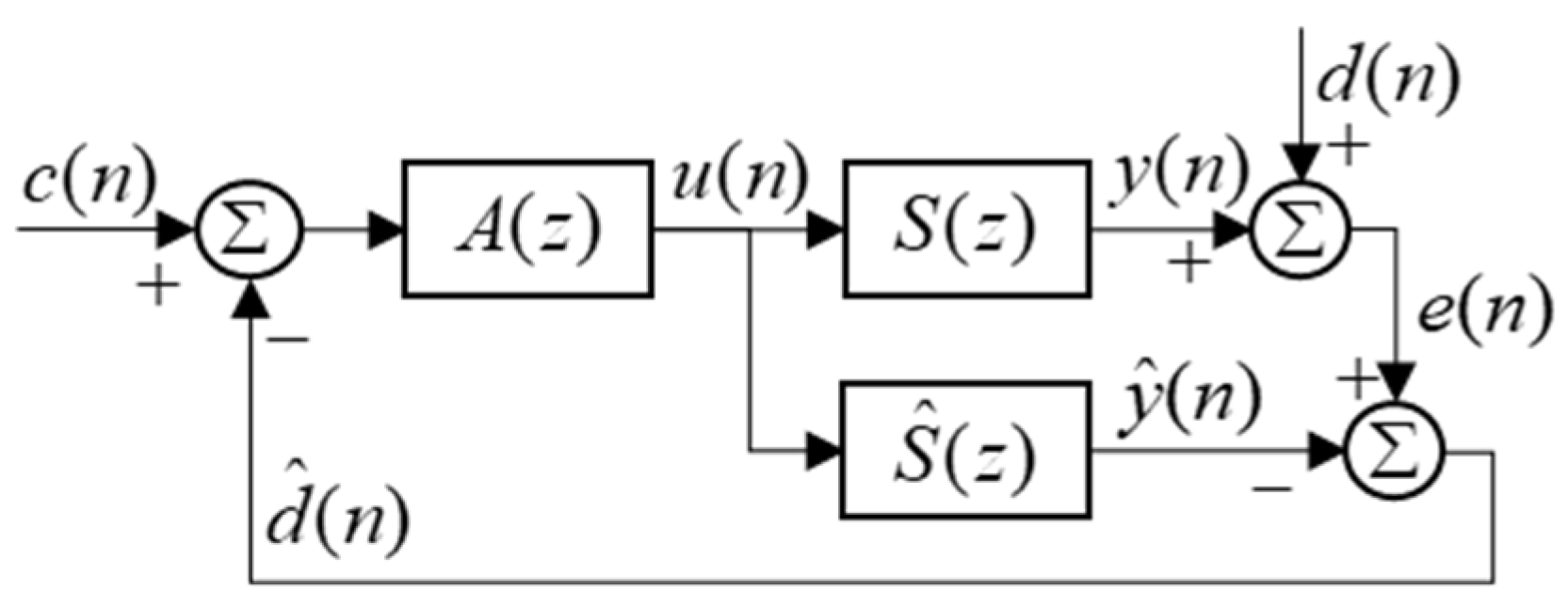
2.2. Novel ASE System Using a PZT-Plate Actuator and ASE Algorithm

A novel ASE system is proposed and is displayed in Figure 2 which is a block diagram of the whole system implemented in a car. It shows the digital signal processor to accommodate the ASE algorithm, the input and output signal flows, the necessary electronics and the PZT-plate actuator. The PZT-plate actuator is considered as a secondary actuator that generates sound to supplement poor engine sound. The PZT actuator was bonded on a plate at the mounting location of the rear mirror of a car, as illustrated in Figure 2.
In this system, the primary path is considered as the acoustic relationship between the primary source, which is the explosion in the engine cylinders of a car, and the microphone installed at the driver’s ear location. The secondary path is defined as the electro-acoustic relationship between the PZT-plate actuator and the microphone.
The ASE algorithm proposed in this study is a purely feedforward control form, as shown in the dashed box in Figure 2. The proposed algorithm is devised to make the sound at the driver’s ear equal to the pre-defined target sound at a certain engine RPM. Usually, the target sound is strictly defined by a professional sound designer to satisfy the required sound quality of a specific car. (However, a reasonable target sound was used for only three engine orders, say C3, C5, and C6, in this study to investigate the feasibility of this proposed approach.)
As the target sound c ( n ) is pre-defined by an RPM-amplitude table of specific engine orders to supplement poor engine sound, once the engine RPM is given, the proposed ASE algorithm automatically generates the control signal u ( n ) in accordance with the pre-defined target sound table. However, the control filter A ( z ) must have an ability to predict the inverse property of the secondary path to generate correct target sound at the driver’s ear in real-time environment. Thus, in this section, the proposed ASE algorithm is described with theoretical symbols and notations to clarify the operation of this approach. For convenience, all symbols are represented in the discrete form using variables of n in time-domain and z in z-domain.
The ASE algorithm in Figure 2 can be summarized in a simple block diagram, as depicted in Figure 3, where A ( z ) , S ( z ) , d ( n ) , and y ( n ) are the inverse control filter, actual secondary path, disturbance signal (original engine sound), and output signal (supplemented sound by the ASE), respectively.
With a specific engine order at a certain RPM, the proposed ASE algorithm endeavors to make the order sound level in the error signal e ( n ) equal to the target sound c ( n ) . The error signal e ( n ) can be written, from the block diagram in Figure 3, as:
e ( n ) = d ( n ) + y ( n ) =   d ( n )   +   A ( z ) S ( z ) c ( n ) .
Assuming that the original engine sound d ( n ) is poor and the target sound c ( n ) is much greater than d ( n ) , Equation (3) can be expressed as:
e ( n ) A ( z ) S ( z ) c ( n ) .
Furthermore, provided that the control filter A ( z ) is identical to the inverse of the secondary path S ( z ) , Equation (4) can be given by:
e ( n ) c ( n )   , if   A ( z ) S 1 ( z ) .
This indicates that the sound e ( n ) at the driver’s ear will follow the target sound c ( n ) perfectly, if A ( z ) is the exact inverse of S ( z ) .
However, in practice, this cannot be achieved with a stable A ( z ) since S ( z ) in the proposed system is non-minimum phase. In such a case, A ( z ) can be realized by the inverse modelling approach [20] using a modelling delay Δ , as shown in Figure 4a,b.
The arrangement in Figure 4a shows a feedforward control system where y ^ ( n ) follows the desired signal d ( n ) which is equal to c ( n Δ ) . y ^ ( n ) and d ^ ( n ) are the estimates of the output and disturbance signals, respectively, and S ^ ( z ) is the secondary path model. Assuming that A ( z ) and S ^ ( z ) are linear and time-invariant, they can be rearranged as shown in Figure 4b. Then, the optimal FIR filter coefficient vector of the FIR device A ( z ) , a o p t , to minimize the expectation of the squared e ( n ) can be calculated by the Wiener filter design process and given as [21]:
a o p t = [ R + β I ] 1 p ,
where β is a regulation parameter to prevent excessively large values of a o p t and I is the identity matrix. R is the auto-correlation matrix of the estimate of the filtered target signal vector r ^ ( n ) and can be written as:
R = E [ r ^ ( n ) r ^ T ( n ) ] ,
where r ^ ( n ) = [ r ^ ( n ) r ^ ( n 1 ) r ^ ( n I + 1 ) ] T , I is the length of a o p t , and the superscript T means transpose. p is cross-correlation vector of r ^ ( n ) and d ( n ) and can be given as:
p = E [ r ^ ( n ) d ( n ) ] .
However, such implementation of A ( z ) as a o p t can be computationally expensive for the convolution operation of c ( n ) and a o p t and also lead to a time lag of u ( n ) due to the modelling delay.
To overcome these drawbacks, in the proposed ASE algorithm, A ( z ) is redefined to compensate for only the magnitude response of the secondary path, and so it is given as [22]:
A ( z ) = | S ^ 1 ( z ) | .
This can be a reasonable implementation of A ( z ) if the purpose of ASE is to enrich the amplitude of the engine order sound to that of the target sound regardless of their phase. This approach has two advantages. The first is that the computational efficiency can be significantly improved since A ( z ) in Equation (9) can be simply implemented as a gain varied according to the frequency of c ( n ) . Thus, u ( n ) can be produced through just one scalar multiplication operation without any convolution operation. The second is that the time lag due to the modelling delay is eliminated, so the supplemented engine sound y ( n ) can immediately correspond to a sudden frequency change in the actual engine sound d ( n ) .
It should be noted that even if A ( z ) is designed to perfectly cancel the magnitude of the secondary path, there may be a difference between the amplitudes of c ( n ) and e ( n ) when d ( n ) has a large value which is not negligible compared with that of c ( n ) , and the magnitude of the difference depends on both the amplitude and phase of d ( n ) .
In fact, the arrangement of the ASE algorithm in Figure 3 can be considered a special case of a feedback control algorithm with the internal model control (IMC) structure [21] illustrated in Figure 5 when the actual secondary path S ( z ) and its model S ^ ( z ) is perfectly identical and d ( n ) is ignored.
This can be proved by applying the above assumptions to Equation (10) which shows the complementary sensitivity function T ( z ) of the IMC feedback control algorithm [21,23]:
T ( z ) = Y ( z ) C ( z ) D ( z ) = A ( z ) S ( z ) 1 + A ( z ) [ S ( z ) S ^ ( z ) ] ,
where Y ( z ) , C ( z ) , and D ( z ) are the z-transforms of y ( n ) , c ( n ) , and d ( n ) , respectively.
This feedback control algorithm has the ability to make e ( n ) follow c ( n ) even when d ( n ) is not negligible due to the feedback structure because the algorithm uses the estimate of the disturbance signal d ^ ( n ) as the feedback signal. However, it is known that the stability of this feedback control algorithm may be extremely sensitive to the accuracy of the secondary path model [22]. This means that the feedback algorithm is considerably vulnerable to changes in the actual secondary path S ( z ) , which may readily occur in the actual environment.
On the other hand, because there is no feedback loop, the proposed purely feedforward ASE algorithm is relatively more stable than the feedback algorithm. Nevertheless, it has potential instability because A ( z ) cannot deal with changes in the actual secondary path S ( z ) . Thus, in this study, in order to design a robustly stable A ( z ) , the secondary path was measured in various conditions within given bounds, and the measured paths were reflected in the design process.

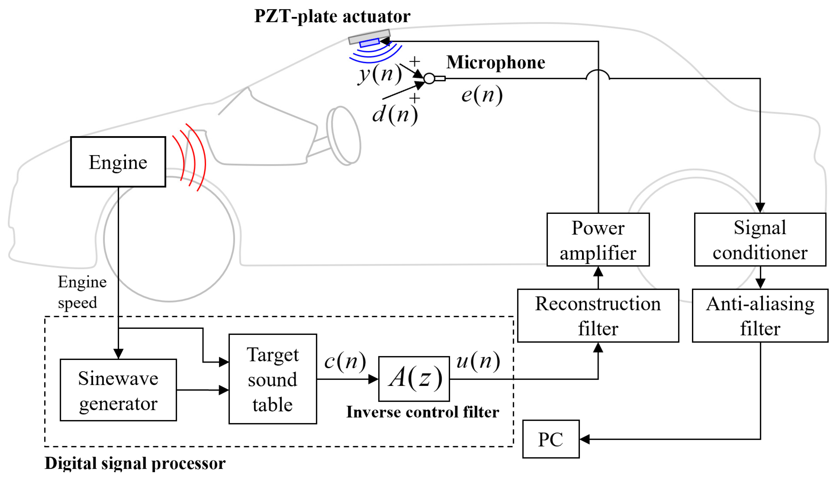
3. Experimental Set-Up

3.1. Implementation of the Proposed ASE System

The proposed ASE system was implemented in a 4-cylinder gasoline sedan for the experiment, as illustrated in Figure 2. The system consists of a real-time digital signal processor (dSPACE, DS1401, Germany) to receive the input signals (engine speed), to compute the ASE algorithm, and to deliver the output signals (control signal).
The engine speed in RPM was obtained from the CAN of the car and the control signal was delivered to three PZT actuators (Fuji Ceramics, C-5H which is equivalent to PZT5H, Japan) as the secondary actuator through a power amplifier (PCB Piezotronics, 790A01, USA). The PZT actuators were bonded on a flat steel plate to radiate structure-borne sound.
A microphone (PCB Piezotronics, 377B02, USA) was installed to measure noise at the driver’s right ear location and its noise signal was amplified by a signal conditioner (PCB Piezotronics, 480E09, USA). The distance between the center of the three PZT actuators and the microphone was about 350 mm, which is a crucial factor to satisfy the causality condition of the ASE algorithm.
Two low-pass filters were used for anti-aliasing and reconstruction of the input and output signals of the ASE system, respectively, and their cut-off frequencies were both 1000 Hz. The ASE algorithm was operated at the sampling frequency of 10,000 Hz during the real-time control experiment.

3.2. Implementation of the PZT-Plate Actuator for Sound Radiation

The three PZT actuators were bonded on a component plate of the front cross member at the roof of the car, as shown in Figure 2 and Figure 6. As shown in Figure 6, the front cross member used in this study was a bent metal structure with the dimensions of about 1000 mm × 90 mm × 2 mm (length × width × thickness). The component plate has an almost square shape with sides about 80 mm long and is positioned in the middle of the front cross member which is the mounting location of the rear mirror.
This plate with the PZT was chosen after considerable inspection. In the process of choosing a proper PZT location, several critical factors were scrutinized. These included a sufficient magnitude of the structure-borne sound power output to satisfy the required target sound level, a suitable response of the secondary path and whether the causality condition was satisfied.
As shown in Figure 6, one large (40 × 20 × 1 mm) and two small (30 × 20 × 1 mm) rectangular actuators were used to cover the component plate (this was because the middle part of the plate was dented.), and they were electrically wired to work as a single actuator. Their electromechanical specifications can be found in reference [24].

4. Experiment Results and Discussions

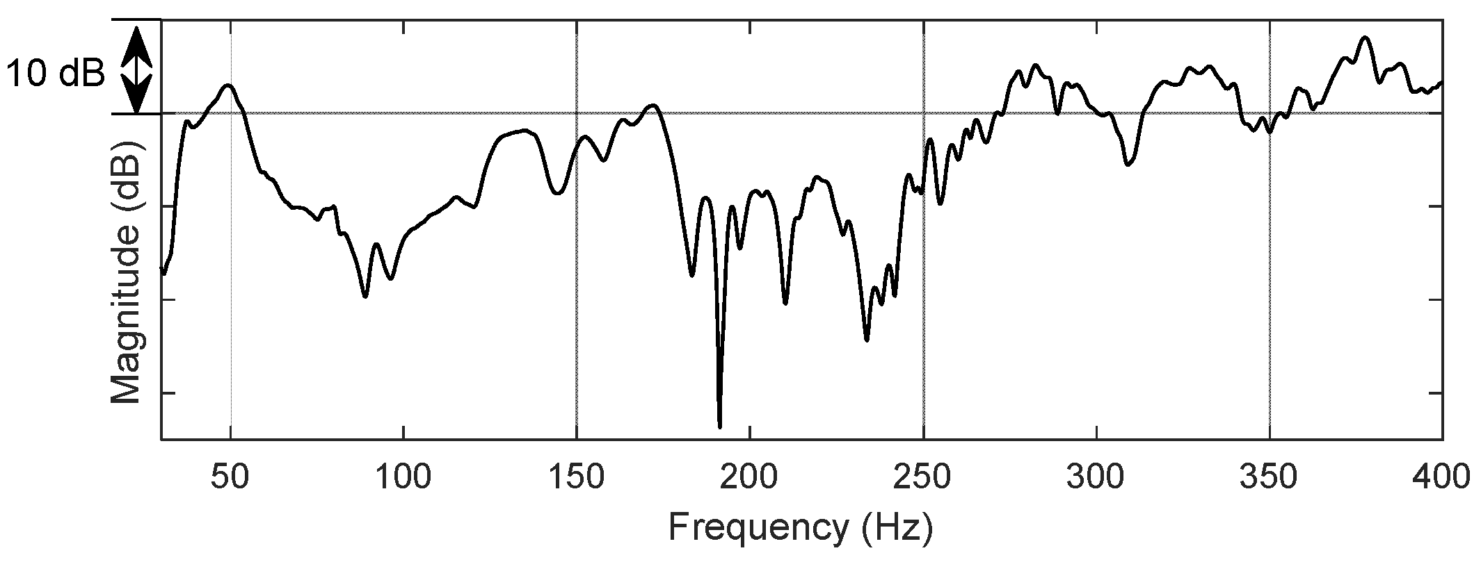
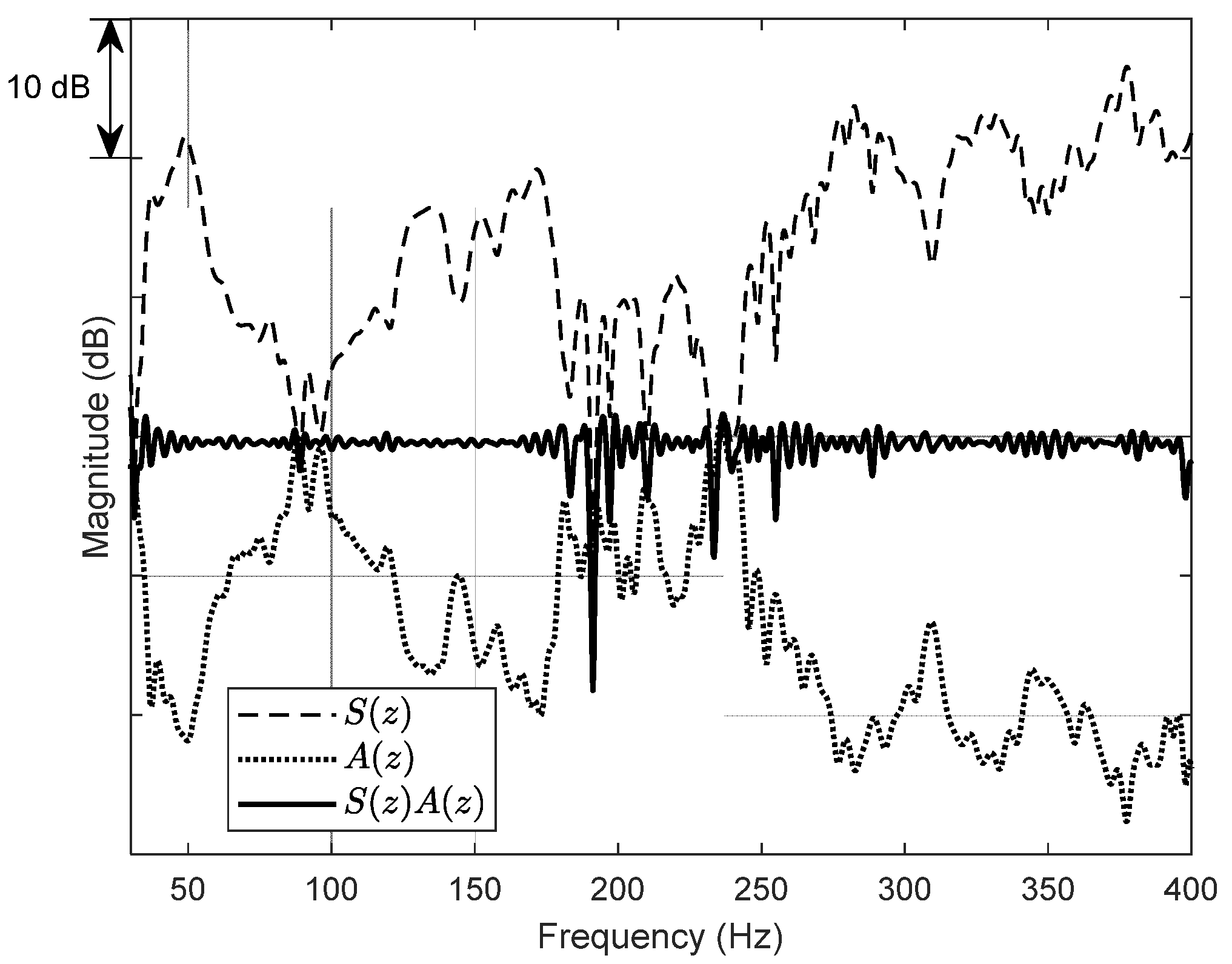
4.1. Properties of the Secondary Path

The secondary path of the PZT-plate actuator was measured under various conditions, such as temperature variation, within given bounds, and the frequency of the input signal, a sinusoid, was linearly swept from 30 Hz to 400 Hz for 10 s when the amplitude of the input voltage to the PZT actuator was 200 V. One of the measured magnitude responses of the secondary path is plotted in Figure 7. This magnitude response shows not only the acoustic characteristics of the cabin but also the mechanical properties of the PZT-plate actuator.
From the magnitude response, it was found that the PZT-plate actuator was able to effectively produce structure-borne sound near 50, 130, 170, 280, 325, and 375 Hz corresponding to the resonance frequencies. However, it was relatively poor at generating sound around the anti-resonance such as 90, 190, 210, and 230 Hz. Besides, the magnitude response at other frequencies showed a fluctuating aspect. These features represent a characteristic of vibro-acoustic sound from the PZT-plate actuator, and the magnitude response contrasts obviously with that of a door loudspeaker, which was relatively flat, as reported in reference [25].
The secondary path model S ^ ( z ) was designed from the nominal path as an FIR filter with 3000 coefficients at the sampling frequency of 10,000 Hz. The normalized impulse response of S ^ ( z ) was plotted in Figure 8. It was found that the impulse response lasted even at 2600 samples due to the low damping caused by the mechanical properties of the PZT-plate actuator. Such a long impulse response can increase the required modelling delay and filter length in the design of the inverse control filter of the secondary path [26].

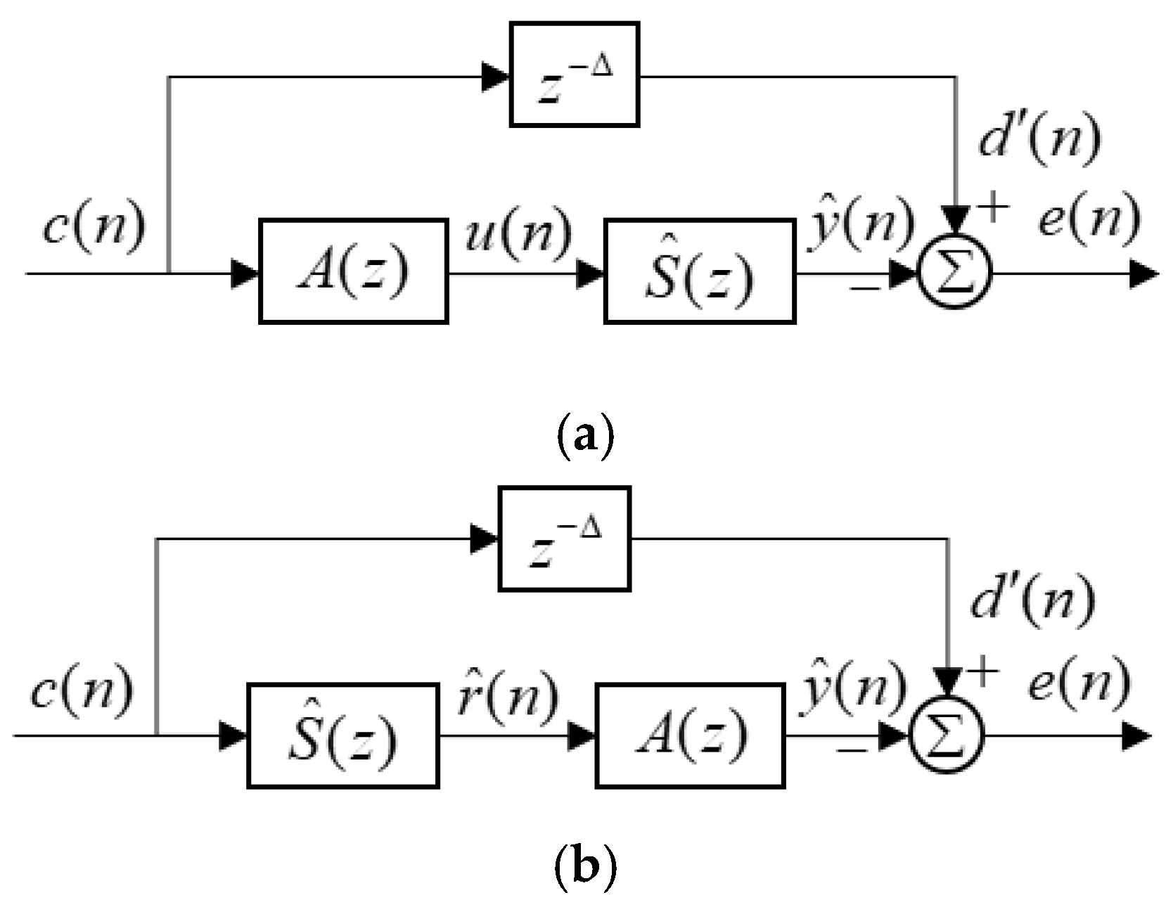
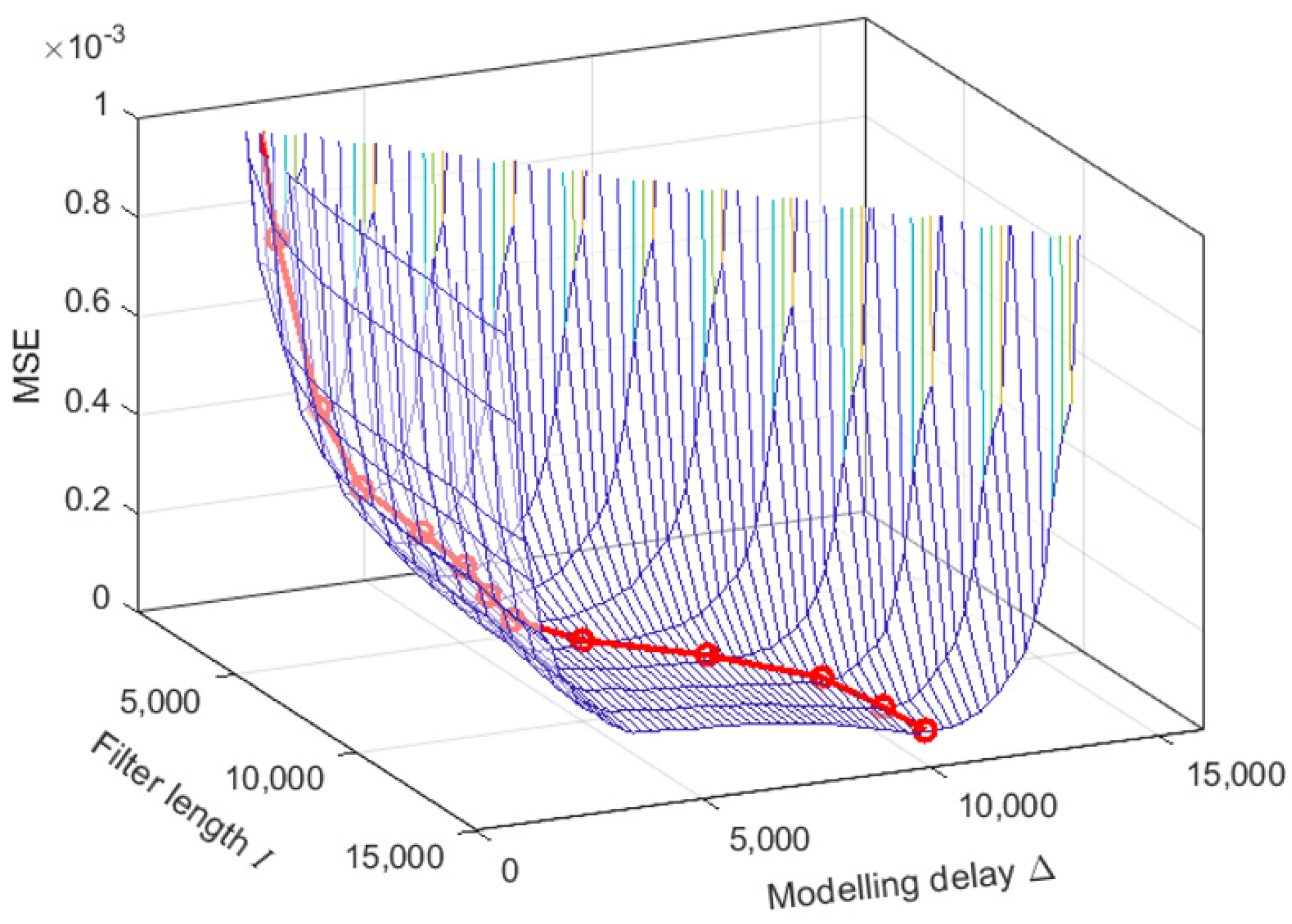
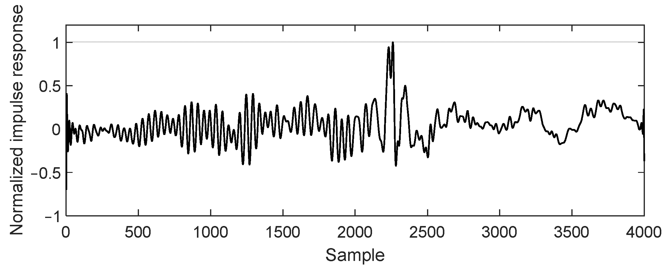
4.2. Implementation of A(z) of the Proposed ASE Algorithm

In order to obtain the control filter A ( z ) in Equation (9) of the ASE algorithm, firstly, inverse modelling was conducted to calculate the optimal FIR filter of the inverse secondary path through Equations (6)–(8), and then its modulus was taken. The main factors associated with the accuracy of the inverse FIR filter in the design process were the filter length I and the modelling delay Δ . Hence, a number of calculations were conducted to determine the optimal values of I and Δ which minimize the mean square error (MSE) between the desired signal d ( n ) and the output signal y ^ ( n ) plotted in Figure 4a. The filter length I was varied from 1000 to 14,000 samples, and in each I , the modelling delay Δ was changed from 0 to I samples.
Figure 9 shows the MSE surface against I and Δ , and the minimum MSE at each I (the thick line with circles) and its optimal Δ . The minimum MSE had a smaller value as I was increased, and so it may be even lower above 14,000 samples of I .
However, in this study, a o p t in Equation (6) was designed with 4000 samples of I and its optimal Δ of 2400 samples based on some practical considerations including adequate response speed to a rapid change of engine speed, the computational complexity, and the MSE value as shown in Figure 10.
Then, a o p t was transformed in the z-domain to obtain its magnitude response | S ^ 1 ( z ) | for A ( z ) , as expressed in Equation (9). Figure 11 shows the comparison of the magnitude responses of S ( z ) , A ( z ) , and S ( z ) A ( z ) indicated by dashed, dotted, and solid lines, respectively. Here, the magnitude response S ( z ) is the same as that given in Figure 7. This comparison indicates that A ( z ) is well-designed to compensate for the magnitude of S ( z ) in most of the frequency range from 30 to 400 Hz within about ± 5 dB of errors, except for about 190 and 230 Hz which are the anti-resonance frequencies of S ( z ) . At these two frequencies, the magnitude responses of A ( z ) were about 19 dB and 9 dB less than ideal magnitudes for perfect compensation, respectively. This is because A ( z ) was designed to have robust stability at those anti-resonance frequencies that can be easily changed in the secondary path by using the nominal secondary path. In addition, β in Equation (6) affected A ( z ) to prevent it from having excessive magnitudes. The designed A ( z ) was implemented in the ASE algorithm using a lookup table.

4.3. Spectrogram Analysis after ASE

A real-time control experiment of the proposed ASE system was carried out while the engine was swept from 1000 to 3900 RPM for about 9 s at the neutral mode. The amplitude values in terms of SPL of the three orders were set to have greater SPLs than its original SPLs, but gradually higher as the engine RPM increased.
Figure 12a,b show the comparison of the spectrograms of the engine sound measured at the microphone before and after ASE. In Figure 12a, it can be observed that there were a number of engine order sounds of the four-cylinder car, and the C2 order was the most dominant. The C4, C6, and C8 orders, which are integer multiples of the C2, were also noticeable, but they were less dominant than the C2 order. Among them, it was found that especially the C6 order had the poorest SPL. In addition, the odd integer orders such as C3 and C5, which are important in terms of sound quality, were not observed clearly.
In Figure 12b, it can be seen that the ASE system changed the spectrogram dramatically with the three orders becoming more distinct as their SPLs were significantly enriched. The C6 order became the most dominant order of the enriched engine sound, and the C3 and C5 orders became noticeably observable. Moreover, it was found that the SPLs of the three orders gradually increased with the engine RPM, which followed the target sound (Please see Figure 13).

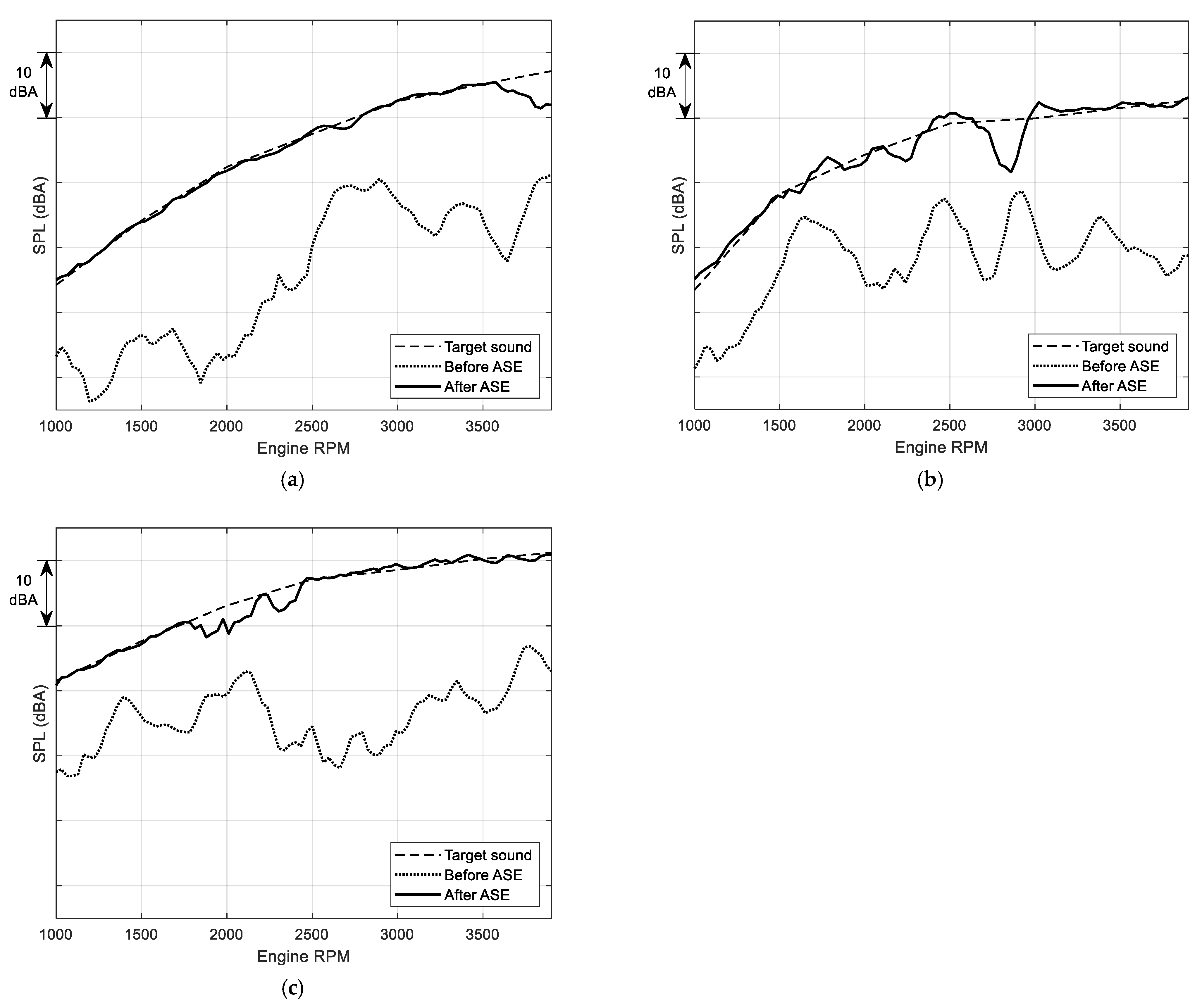
4.4. Performance Analysis after ASE

Figure 13 shows the comparison of the A-weighted SPLs of the three orders (C3, C5, and C6) before (dotted lines) and after (solid lines) ASE with the target sounds (dashed lines) against engine speed. The SPLs of the orders are plotted in Figure 13. In addition, the target error L TE ( f ) is defined to assess the control performance of the proposed ASE system, which is given as:
L TE ( f ) = L ( f ) L target ( f ) ,
where L ( f ) and L target ( f ) are the SPLs of the measured engine sound and the target sound, respectively, at the corresponding frequency f in RPM. L TE ( f ) can be expressed as the root mean square (RMS) over the engine speed range of 1000–3900 RPM as L TE , RMS . The L TE , RMS of the three controlled orders are summarized in Table 1.
As shown in Figure 13a, the SPL of the C3 order before ASE was about 10–30 dBA less than that of the target sound. After ASE, this insufficient SPL was greatly increased to close to the target level and its L TE ( f ) was −5 to 1 dBA. Thus, L TE , RMS after ASE achieved 0.9 dBA which was 19.1 dBA less than that before ASE, as shown in Table 1.
In the case of the C5 order, as shown in Figure 13b, the SPL before ASE was enhanced by 5–25 dBA, thus reaching a level near to its target sound. Thus, L TE , RMS of the C5 order was improved from 17.4 dBA to 1.5 dBA, as shown in Table 1.
As plotted in Figure 13c, the result of the C6 order was similar to that of the C3 and C5 orders. It was found that L TE , RMS after ASE was 1.1 dBA, whereas that before ASE was 19.1 dBA.
However, it is noteworthy that there were large target errors at some engine speeds, such as at around 3800 RPM for the C3 order, at 2300 and 2800 RPM for the C5 order and at 1900 and 2300 RPM for the C6 order. These engine speeds correspond to 190 or 230 Hz, which are the anti-resonance frequencies of the secondary path. The reason for the large target errors is that A ( z ) was designed to not generate a high level of u ( n ) at these frequencies to maintain robust control stability, as can be seen from Figure 11. This degradation in performance was fundamentally due to the properties of the secondary path of the PZT-plate actuator. The component plate used in this study was only a reasonable choice to investigate the feasibility of the use of a PZT-plate actuator for the ASE system, not the perfect or optimized one. For a more practical implementation, it is therefore, very important to design a dedicated plate with vibro-acoustic characteristics suitable for ASE.
Although some target errors were observed, the control experiment results show that A ( z ) , which was implemented in Section 4.2, adequately compensated for the magnitude of the actual secondary path of the PZT-plate actuator so that the error signal e ( n ) followed the target sound c ( n ) . Furthermore, the results indicate the PZT-plate actuator worked properly as a secondary actuator with the ASE algorithm, producing a supplemented engine sound to enrich the poor original sound in the cabin.

5. Conclusions

This paper investigated the feasibility of a proposed ASE system using a PZT-plate as a secondary actuator to enrich the insufficient engine sound of an ICEV. The ASE system was devised with a purely feedforward control approach. Three PZT actuators were bonded on a component steel plate of the front cross member of the car roof. The control filter of the ASE algorithm was designed using an inverse method to compensate for the secondary path. Then, a real-time control experiment was carried out to examine the tracking performance of a pre-defined target sound of three engine orders using the proposed ASE system.
This study contributes to clarifying the relationship between a PZT-plate actuator and its generated sound using proper equations to consider the design of the inverse control filter for compensating the secondary path and to examine the characteristics of the vibro-acoustic secondary path related to the PZT-plate actuator.
The control experiment results showed that the SPLs of the three engine orders were greatly enriched by about 5–30 dBA with small errors. This result indicates that the proposed ASE system using a PZT-plate actuator and the control filter can be an alternative for actively generating sound to achieve a target sound quality in a car.
Especially for EVs, this feasibility study suggests the ASE system is an affordable approach to mask exotic noises due to absence of engine sound which exists in ICEVs. For further practical verification of the proposed ASE system, its effects will be investigated in the future with real-time control experiments while driving on a road.

Author Contributions

Conceptualization, Y.-S.L. and E.Y.; methodology, Y.-S.L.; software, S.R.; validation, Y.-S.L.; formal analysis, Y.-S.L., S.R. and E.Y.; investigation, J.L. and E.Y.; resources, J.L.; data curation, S.R.; writing—original draft preparation, Y.-S.L.; writing—review and editing, Y.-S.L. and S.R.; visualization, J.L.; supervision, E.Y. All authors have read and agreed to the published version of the manuscript.

Funding

This work was supported by the Incheon National University Research Grant in 2018.

Institutional Review Board Statement

Not applicable.

Informed Consent Statement

Not applicable.

Data Availability Statement

Not applicable.

Conflicts of Interest

The authors declare no conflict of interest.

References

  1. Fuller, C.R.; Elliott, S.J.; Nelson, P.A. Active Control of Vibration; Academic Press: London, UK, 1996. [Google Scholar]
  2. Lee, Y.-S. Active Control of Smart Structures Using Distributed Piezoelectric Transducers. Ph.D. Thesis, University of Southampton, Southampton, UK, 2000. [Google Scholar]
  3. Lee, Y.-S.; Gardonio, P.; Elliott, S.J. Volume velocity vibration control of a smart panel using a uniform force actuator and an accelerometer array. Smart Mater. Struct. 2002, 11, 863–873. [Google Scholar] [CrossRef]
  4. Schirmacher, R. Active design of automotive engine sound. In Proceedings of the Audio Engineering Society Convention, München, Germany, 10–13 May 2002; p. 112. [Google Scholar]
  5. Moon, S.; Park, S.; Park, D.; Yun, M.; Chang, K.; Park, D. Active sound design development based on the harmonics of main order form engine sound. J. Audio Eng. Soc. 2020, 68, 532–544. [Google Scholar] [CrossRef]
  6. Park, D.C.; Jo, E.S.; Hong, S.; Ksakan, M. Development of personalized engine sound system using active sound design technology. SAE Int. J. Passeng. Cars-Mech. Syst. 2015, 8, 862–867. [Google Scholar] [CrossRef]
  7. Kim, S.; Lee, S.M.; Park, D.C.; Chang, K.J.; Lee, S.K. A Systematic approach to engine sound design for enhancing sound character by active sound design. ASE Int. J. Passeng. Cars-Mech. Syst. 2017, 10, 691–702. [Google Scholar] [CrossRef]
  8. Bodden, M.; Belschner, T. Comprehensive automotive active sound design-Part 1: Electric and combustion vehicles. In Proceedings of the INTER-NOISE and NOISE-CON Congress and Conference, Daejeon, Republic of Korea, 16–19 November 2014; Volume 249, pp. 3214–3219. [Google Scholar]
  9. Pruetz, J.E.; Eisele, G.; Govindswamy, K.; Steffens, C. Active Sound Design Methodologies for Hybrid and Electric Vehicles; SAE Technical Paper 2021; No. 2021-01-1019; SAE: Warrendale, PA, USA, 2021. [Google Scholar] [CrossRef]
  10. Gwak, D.Y.; Yoon, K.; Seong, Y.; Lee, S. Application of subharmonics for active sound design of electric vehicles. J. Acoust. Soc. Am. 2014, 136, EL391–EL397. [Google Scholar] [CrossRef] [PubMed]
  11. Cao, Y.; Hou, H.; Liu, Y.; Tang, L.; Li, Y. Engine order sound simulation by active sound generation for electric vehicles. SAE Int. J. Veh. Dyn. Stab. NVH 2020, 4, 151–164. [Google Scholar] [CrossRef]
  12. Elliott, S.J.; Stothers, I.M.; Nelson, P.A.; McDonald, A.M.; Quinn, D.C.; Saunders, T. The active control of engine noise inside cars. In Proceedings of the INTER-NOISE and NOISE-CON Congress and Conference, Christchurch, New Zealand, 16–18 November 1998; pp. 987–990. [Google Scholar]
  13. Couche, J.; Fuller, C. Active control of power train and road noise in the cabin and a sports utility vehicle with advanced speakers. In Proceedings of the 1999 International Symposium on Active Control of Sound and Vibration, Fort Lauderdale, FL, USA, 2–4 December 1999; pp. 2–4. [Google Scholar]
  14. Lee, Y.-S.; Ryu, S.; Yoo, E.; Lim, C. A feasibility study of an ESG to suppress road noise of a Car. Appl. Sci. 2022, 12, 2697. [Google Scholar] [CrossRef]
  15. Christian, C.; Benbara, N.; Rebillant, M.; Mechbal, N. Piezoelectric transducer for low frequency sound generation on surface loudspeakers. In Proceedings of the IX ECCOMAS Thematic Conference on Smart Structures and Materials, Paris, France, 8–11 July 2019; pp. 1–10. [Google Scholar]
  16. Simonich, J.; Partick, W.; Bolleman, B. Characterization of SpeakerTpae-a new thin film actuator for active noise control. In Proceedings of the 4th AIAA/CEAS Aeroacoustics Conference, Toulouse, France, 2–4 June 1998; p. 2352. [Google Scholar]
  17. Fahy, F.; Gardonio, P. Sound and Structural Vibration, 2nd ed.; Academic Press: London, UK, 2007. [Google Scholar]
  18. Warnaka, G.E.; Warnaka, M.E.; Parrella, M.J. Vehicular Loudspeaker System. U.S. Patent No. 6,356,641 B1, 12 March 2002. [Google Scholar]
  19. Zenker, B.; Dannemannm, M.; Geller, S.; Holeczek, K.; Weissenborn, O.; Altinsoy, M.E.; Modler, N. Structure-integrated loudspeaker using fiber-reinforced plastics and piezoelectric transducers—Design, manufacturing and validation. Appl. Sci. 2020, 10, 3438. [Google Scholar] [CrossRef]
  20. Widrow, B.; Walach, E. Adaptive Inverse Control; Prentice-Hall International Ed.: Hoboken, NJ, USA, 1996. [Google Scholar]
  21. Elliott, S.J. Signal Processing for Active Control; Academic Press: London, UK, 2001. [Google Scholar]
  22. Ryu, S.; Lim, J.; Lee, Y.-S.; Yoo, E.; Lim, C. Enhancing engine order sound using additive feedforward control for a secondary path with uncertainty at higher frequencies. Appl. Sci. 2022, 12, 4486. [Google Scholar] [CrossRef]
  23. Rees, L.E.; Elliott, S.J. Adaptive algorithms for active sound-profiling. IEEE Trans. Audio Speech Lang. Process. 2006, 14, 711–719. [Google Scholar] [CrossRef]
  24. Fuji Ceramics, Product Catalog, Fuji Ceramics. Available online: https://www.fujicera.co.jp/download/ (accessed on 13 November 2022).
  25. Ryu, S.; Kim, J.; Lee, Y.-S. Active sound profiling of narrowband signals for improving sound quality in an enclosed space. Multimed. Tools Appl. 2017, 76, 24595–24607. [Google Scholar] [CrossRef]
  26. Lee, Y.-S.; Elliott, S.J. Active position control of a flexible smart beam using internal model control. J. Sound Vib. 2001, 242, 767–791. [Google Scholar] [CrossRef]
Figure 1. Radiated sound from the combination of a rectangular PZT actuator and a rectangular plate propagating to the ear location. (a) Three-dimensional view. (b) Cross-section at the middle of the combination in the y-axis.
Applsci 12 12017 g001
Figure 2. Block diagram of the proposed ASE system using a PZT actuator bonded on a plate at the mounting location of the rear mirror of a car.
Applsci 12 12017 g002
Figure 3. Simply expressed block diagram of the ASE algorithm.
Applsci 12 12017 g003
Figure 4. (a) Block diagram of a feedforward control for following the delayed target sound using a modelling delay. (b) Rearrangement of the block diagram for the design of the inverse control filter A ( z ) .
Applsci 12 12017 g004
Figure 5. Block diagram of a feedback target tracking control algorithm with the IMC structure.
Applsci 12 12017 g005
Figure 6. Set-up of the PZT-plate actuator.
Applsci 12 12017 g006
Figure 7. A measured magnitude response of the secondary path of the PZT-plate actuator.
Applsci 12 12017 g007
Figure 8. Impulse responses of the secondary path model.
Applsci 12 12017 g008
Figure 9. MSE surface against filter length I and modelling delay Δ , and the minimum MSE at each I (the thick line with circles).
Applsci 12 12017 g009
Figure 10. Impulse response of the optimal FIR inverse filter a o p t .
Applsci 12 12017 g010
Figure 11. Comparison of the magnitude responses of S ( z ) , A ( z ) , and S ( z ) A ( z ) indicated by dashed, dotted, and solid lines, respectively.
Applsci 12 12017 g011
Figure 12. Engine RPM-frequency spectrograms of the measured engine sounds at the driver’s ear location. (a) Before ASE. (b) After ASE.
Applsci 12 12017 g012
Figure 13. Comparisons of the SPLs of the measured engine sound before (dotted lines) and after (solid lines) ASE with the target sounds (dashed lines). (a) C3 order. (b) C5 order. (c) C6 order.
Applsci 12 12017 g013
Table 1. Summary of the control performance of the proposed ASE system for the C3, C5 and C6 orders.
L TE , RMS (dBA)
Engine orderC3C5C6
Before ASE20.017.419.1
After ASE0.91.51.1
Publisher’s Note: MDPI stays neutral with regard to jurisdictional claims in published maps and institutional affiliations.

