Article

Mechanical Strength Decay Evaluation of Excavation Unloaded Rock Mass under Freeze-Thaw Conditions

School of Architecture and Civil Engineering, Xi’an University of Science and Technology, Xi’an 710054, China
*
Author to whom correspondence should be addressed.
Appl. Sci. 2022, 12(23), 12205; https://doi.org/10.3390/app122312205
Submission received: 16 November 2022 / Revised: 25 November 2022 / Accepted: 25 November 2022 / Published: 29 November 2022

Abstract

:
The quality of excavated and unloaded rock masses on steep and high slopes in cold regions is prone to deterioration, which in turn affects the long-term stability and safety of excavated slopes. Based on a triaxial unloading-damage test of sandstone, the unloading quantity was used to analyze the evolution law of unloading damage; a freeze-thaw cycle test of the unloaded-damaged samples was carried out, and it was found that the average change in porosity and the reloading peak strength damage rate after freeze-thaw increased with the increase in the number of freeze-thaw cycles, and the porosity change characteristics were independent of the value of the confining pressure at the time of the unloading damage. An exponential decay model was used, and based on the average change in porosity after freeze-thaw, a freeze-thaw strength decay model that can take into account the effect of confining pressure was established, and its ability to predict the strength decay of unloaded-damaged rock samples after freeze-thaw was verified by experimental data. The research results provide a reference for the evaluation of freeze-thaw degradation of unloaded rock masses during slope excavation in cold regions.

1. Introduction

With the increase in construction in cold regions, the freeze-thaw deterioration of rock masses has become a key issue limiting the stability of projects [1]. For example, the disturbance due to the excavation of a steep and high slope of a reservoir bank in a cold environment (to build a hydropower station) induced a certain range of rock unloading and relaxation as well as fracture development and expansion of fractures in the rock masses at the excavation face [2,3]. This provides a means of intervention for erosion caused by the freeze-thaw cycle due to changes in climate in cold regions, as shown in Figure 1. This change in temperature further induces the deterioration of excavation unloaded rock masses. This kind of rock mass is the primary means to ensure the safety and stability of the excavation slope, and its damage seriously affected the long-term stability and overall safety of the excavated reservoir bank slopes for hydropower projects. Therefore, it is necessary to study the freeze-thaw deterioration characteristics and strength decay model of such damage-stricken rock masses. Such studies can help to accurately evaluate the degree of freeze-thaw damage of rock masses in the unloaded zone of reservoir bank excavation slopes of hydropower projects in cold regions.
The mechanical behavior of rock unloading has been systematically studied by many scholars, and a set of effective test methods and analytical tools have been established. The triaxial unloading test was conducted to investigate the unloading mechanical properties of rock samples with different unloading rates, unloading onset stress levels, and unloading stress paths [4,5,6,7,8,9,10,11,12]. Qiu [13] proposed an incremental cyclic loading-unloading pressure test by improving the unloading test method to explore the quantitative analysis of microrupture induced by stress state change during peritectic pressure unloading and found that the unloading damage of rock samples was mainly caused by transgrain and intergrain fracture, shear slip and parallel secondary fracture. Li [14] analyzed the energy evolution characteristics of granite during unloading, where the ratio of dissipated strain energy to total strain energy can describe the degree of deformation damage during the unloading of rock samples. The unloading damage leads to an increase in pore fractures inside the rock sample, which provides an intervention channel for permeable water and intensifies the water-rock coupling, inducing a sharp acceleration in the unloading process or an intensification in the unloading damage [15,16]. The microstructural characteristics of rock samples with different degrees of unloading damage were studied by nuclear magnetic resonance (NMR) [17,18]. The studies found that the porosity, T2 spectrum distribution, and T2 peak area of the unloading-damaged rock samples increased with the degree of unloading damage, and the unloading damage of the rock samples was mainly triggered by the increase in the number and size of pores. Jiang [19] performed a predictive analysis of the time-lag failure of sandstone unloading damage based on reformed group theory and using a logistic model. Manouchehrian [20] used the finite element method to simulate the damage of rocks under unloading conditions and found that the degree of damage was related to the height of the rock sample and the magnitude of the surrounding pressure. Some scholars [21,22,23] explored the differences between the physical and mechanical properties of rock samples under different unloading damage conditions and intact rock samples from the perspective of energy analysis, taking unloaded-damaged rock samples as the object. The relationship between the cumulative acoustic emission (AE) counts and the quiet period with the unloading point was also investigated by acoustic emission test experiments, and it was found that the uniaxial damage mode of rock samples changed from shear damage to tensile damage with the intensification in unloading damage.
In addition, the freeze-thaw erosion induced by the changes in temperature in cold environments causes the deterioration of the quality of the engineering rock mass. Many scholars have systematically studied the damage evolution process, dynamic and static mechanical properties of rocks with different lithologies under freeze-thaw environments, and the effect of freeze-thaw conditions [24,25,26,27,28,29,30,31]. To estimate the strength loss of rocks after freeze-thaw cycles, Kolay [32] developed a multiple regression model consisting of uniaxial compressive strength, dry density, number of cycles, and porosity based on multiple linear regression analysis to predict with high accuracy the uniaxial compressive strength of rocks (similar to the present test) after 25 freeze-thaw cycles. Mutluturk [33] used an exponential decay model for the first time to describe the loss of freeze-thaw strength of rocks and verified the validity of the model by freeze-thaw tests on 10 different lithologies. Aral [34], Jamshidi [35], Eslami [36], and Wang [37] studied the relationship between the physical and mechanical properties of rocks after freeze-thaw cycles and the number of freeze-thaw cycles using an exponential function model and evaluated the disintegration rate of rocks under the action of freeze-thaw cycles using decay constants and the half-life of each mechanical parameter. Gao [38] and Xu [39] theoretically established a rock strength deterioration model and verified its rationality based on the trends of the expansion of pores or microfractures after freeze-thaw cycles. Mousavi [40], Li [41], and Wang [42] studied the freeze-thaw deterioration characteristics of rocks using fine structure testing techniques (optical microscopy, X-ray diffraction analysis, nuclear magnetic resonance, and CT investigation) and found that the number and size of pores increased after the freeze-thaw cycling of rocks and that medium-sized and small-sized pores increased significantly in size.
In summary, the current research on indoor freeze-thaw tests and strength decay models of rock in cold regions has achieved some results, but there are still some shortcomings, which are mainly reflected in the following two aspects.
  • The study of freeze-thaw degradation characteristics of excavated unloaded rock masses on steep and high slopes in cold regions is inadequate. The excavation unloading relaxation phenomenon on steep and high slopes is significant, and the damage and rupture of rock masses in a certain range in the excavation face provides a means of intervening in freeze-thaw erosion. Therefore, it is necessary to investigate the freeze-thaw erosion and deterioration of excavated and unloaded rock masses of steep and high slopes in regions with seasonal freezing by considering the indoor test program of the interaction between excavation disturbance and freeze-thaw cycles;
  • Most of the studies on freeze-thaw strength decay models are based on the attenuation of uniaxial peak strength deterioration, while the rock body of the reservoir bank of the excavation and unloaded zone is still in a three-way stress state and has an inhibitory effect on freeze-thaw cycle erosion. Therefore, the established freeze-thaw strength decay model should be realistic and reflect the decay of freeze-thaw strength under the stress state of the rock body of the reservoir bank of the excavation and unloaded zone.
In this paper, based on the freeze-thaw cycle erosion of an excavation unloaded rock mass of a steep and high bank slope in hydropower projects in cold regions, the unloaded-damaged sample is prepared for the typical sandstone of a reservoir bank slope of a hydropower station in a cold region through a triaxial unloading confining pressure test. A freeze-thaw mechanics test is then carried out to study the freeze-thaw deterioration characteristics of the unloaded-damaged sample. A freeze-thaw strength decay model is established, and the model parameters are identified by combining the test results and subsequent validation. The results of the study are useful for the prediction of freeze-thaw hazards and the design of support schemes for excavated slopes in cold regions.

2. Test Overview

2.1. Sampling

In this study, yellow sandstone was selected in accordance with the specification requirements of the “Code for Rock Tests in Water and Hydropower Projects” and processed into standard cylindrical specimens of 50 mm × 100 mm. Specimens with obvious defects in appearance were eliminated and the surface flatness of the specimens was ensured to meet the test requirements.

2.2. Test Program

To study the freeze-thaw deterioration characteristics of excavation unloaded rock masses on steep and high bank slopes in cold regions, an integrated indoor test considering the interaction between excavation disturbance and freeze-thaw cycles was carried out. The specific test protocol is as follows:
  • Triaxial compression tests were carried out at three confining pressures (10 MPa, 15 MPa, and 20 MPa), and compressive strengths were obtained at specific circumferential pressures (130.25 MPa, 152.67 MPa, and 172.11 MPa);
  • The excavation unloading stress path of the slope rock in cold regions was simulated and triaxial unloading tests with constant axial pressure unloading of the confining pressure were performed in which the axial stress was loaded to 70% of the compressive strength at a specific surrounding pressure [19]. The confining pressure was then unloaded until the specimen was damaged. To investigate the evolution of the unloading damage process of the enclosing pressure and to obtain unloaded-damaged rock samples that still have a certain load-bearing capacity, the unloaded-damaged sample was prepared by using a stress path with constant unloading of the confining pressure to the target value;
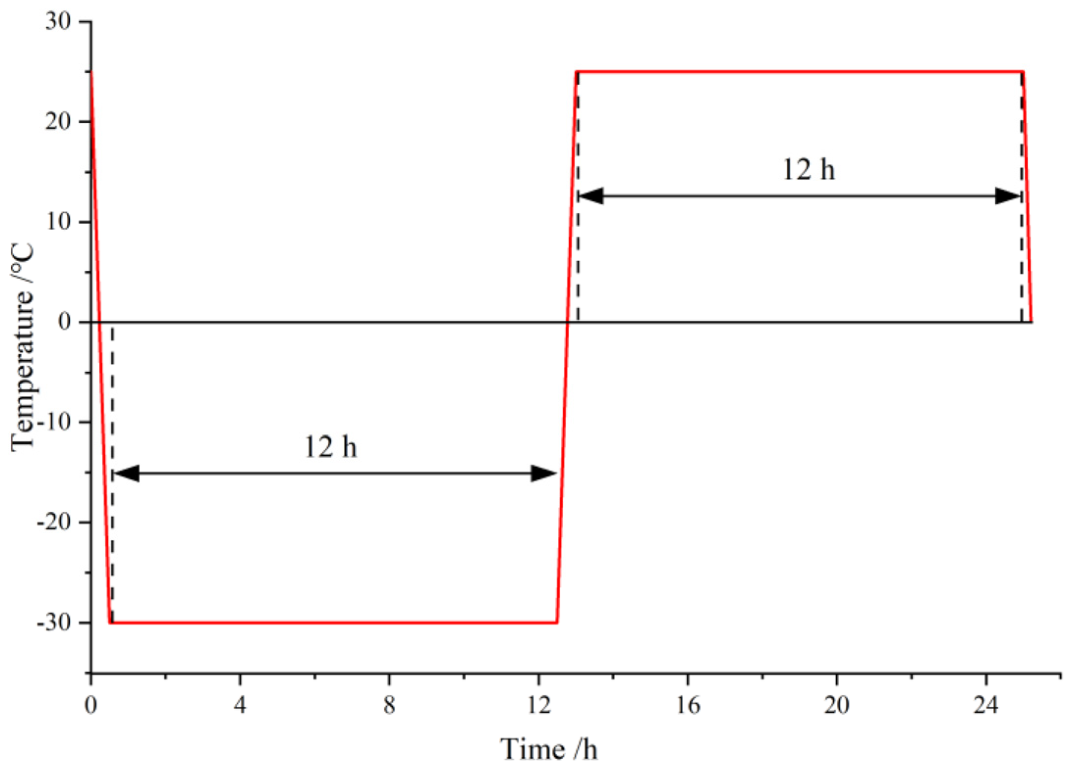
  • The cold region bank slope excavation unloaded rock body is in a three-way force state, and the slope support causes the surface rock body to be affected by the restraint effect, and the freezing and thawing environment triggers the freezing and swelling force caused by the internal water-ice phase change of the rock body in the form of extended development and misalignment slip toward the internal fissures of the rock body. Using the unloaded-damaged sample rock sample as the object, a homemade rock freeze-thaw jig was used (as shown in Figure 2) and combined with the characteristics of the field temperature environment to perform an indoor freeze-thaw cycle test. The freezing temperature was set to −30 °C, the ablation temperature was set to 25 °C, and the sample experienced low-temperature freezing for 12 h followed by room-temperature ablation for 12 h (as shown in Figure 3). A freezing-thawing cycle pre-test was carried out on the unloaded-damaged sample until obvious macroscopic cracks appeared in the rock sample and the rock sample would be broken after the next freezing-thawing cycle. The maximum number of freezing-thawing cycles was measured to be eight times. Therefore, the number of freezing-thawing cycles was finally selected to be zero, two, four, six, and eight times.
  • The unloaded-damaged samples were removed after each freeze-thaw cycle, and the mass, height, diameter, and porosity were recorded. After reaching the target number of freeze-thaw cycles, all rock samples were removed for uniaxial and triaxial reloading tests, in which the values of confining pressure for the triaxial reloading mechanics test were selected as the target values of confining pressure unloading in the preparation of the unloaded-damaged sample, which reflected the stress state after unloading and could better facilitate the investigation of the relationship between the stress state of excavation unloaded rock masses and freeze-thaw erosion.

3. Unloading-Damaged Test Procedure

3.1. Triaxial Unloading Test Analysis

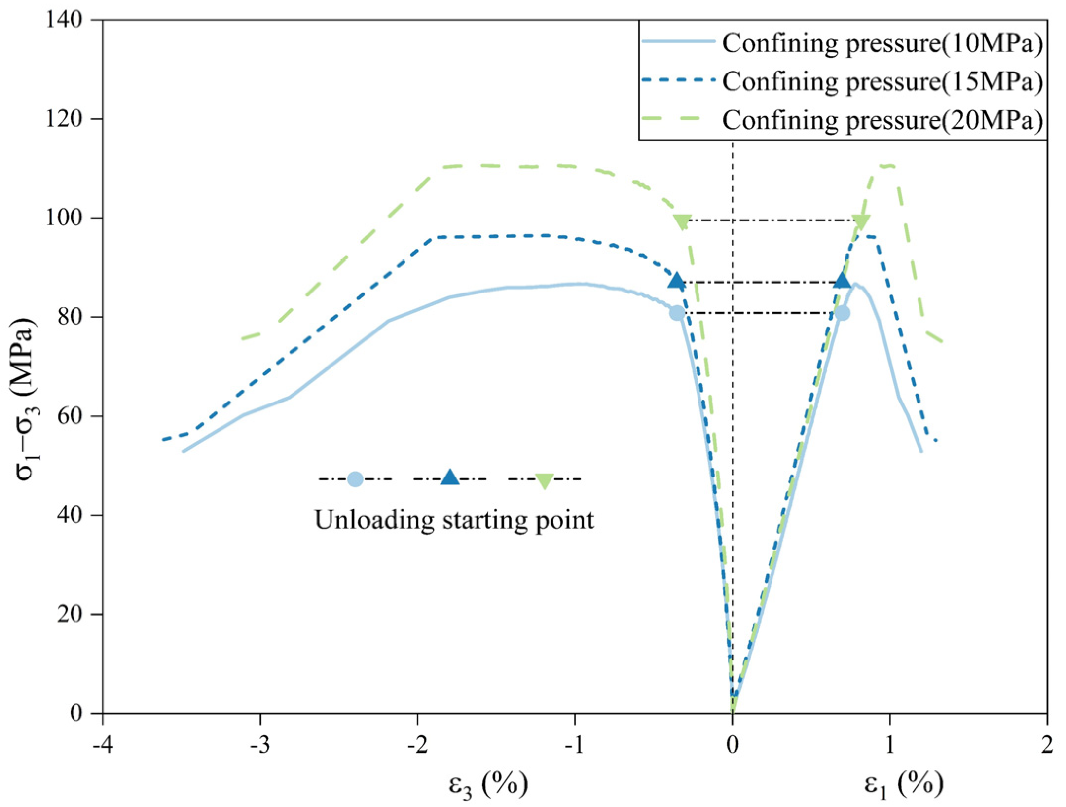
A triaxial unloading test with constant axial unloading confining pressure is carried out to approximately simulate the stress path of slope excavation. The axial stress level is taken as 70%, and the axial pressure is kept constant to unload the surrounding pressure until the specimen is damaged. The surrounding pressure at the time of unloading damage is 3, 4, and 7.5 MPa, and the stress-strain curve is shown in Figure 4.
The unloading quantity [43] is used to characterize the degree of unloading damage and is calculated as:
K = ( σ 3 σ 3 σ 3 σ d ) × 100 %
where K is the confining pressure unloading quantity, σ 3 is the initial confining pressure, σ 3 is the target value of confining pressure unloading, and σ d is the confining pressure value at failure.
To analyze the damage-evolution process of the rock sample during the unloading stage, the unloading quantity is used as the damage classification criterion, and the strain confining pressure increment ratio is introduced (Qiu et al. [44]). The ratio of the strain increment caused by unloading confining pressure to the value of the confining pressure reduction is calculated (Equation (2)). This represents the physical quantity of how fast the axial or circumferential deformation increment changes with each unit of unloaded confining pressure, which better reflects the deformation response of the rock sample during the process of confining pressure unloading.
Δ ε ˙ i = Δ ε i Δ σ 3
where Δ ε ˙ i is the strain confining pressure increment ratio (i = 1,3 represents axial strain and circumferential strain, respectively), Δ ε i is the strain increment between the starting point of the unloading confining pressure and the target value of the confining pressure to the corresponding unloading quantity, and Δ σ 3 is the difference between the starting point of the unloading confining pressure and the corresponding unloading quantity corresponding to the confining pressure target value.
As shown in Figure 5, the strain of the sample under the three groups of confining pressures gradually increases with increasing unloading quantity, and the axial and circumferential strain confining pressure increment ratios gradually increase, reflecting the influence of the size of the unloading quantity on the deformation response of the rock sample during the process of unloading confining pressure. It can be roughly divided into three stages: stage I (0–60% unloading capacity) is the slow section, where the microfractures inside the rock sample are affected by the unloading confining pressure, and the original closed state gradually opened but did not undergo expansion; stage II (60–90%) is the uniform section, with the increase in unloading quantity, the microfractures inside the rock sample continue to develop and expand, the pore structure is damaged to a certain extent, and the axial and circumferential deformation of the rock sample continues; stage III (90–100%) is the accelerated section, the pore fissures inside the rock sample develop, expand, and connect, the structure is rapidly destroyed, and the axial and circumferential deformation increases rapidly.
After the unloading quantity becomes greater than 60%, the rate of change of the axial and circumferential strain confining pressure increment ratio is significantly accelerated. The increase in these strains indicates the opening and continuous expansion of the microfractures induced by unloading action inside the rock sample, and the unloading damage gradually intensifies, so the 60% unloading quantity is the key dividing point of the unloading damage evolution process of the rock sample.

3.2. Preparation of Unloaded-Damaged Samples

Considering the above analysis and under the premise that rock samples are available, to obtain unloaded-damaged rock samples with a certain bearing capacity, a 60% unloading quantity was finally selected to define the degree of unloading damage. Unloaded-damaged sample tests under three kinds of confining pressures were carried out according to the loading and unloading stress paths and loading and unloading rates shown in Figure 6 (Chen et al. [45]).
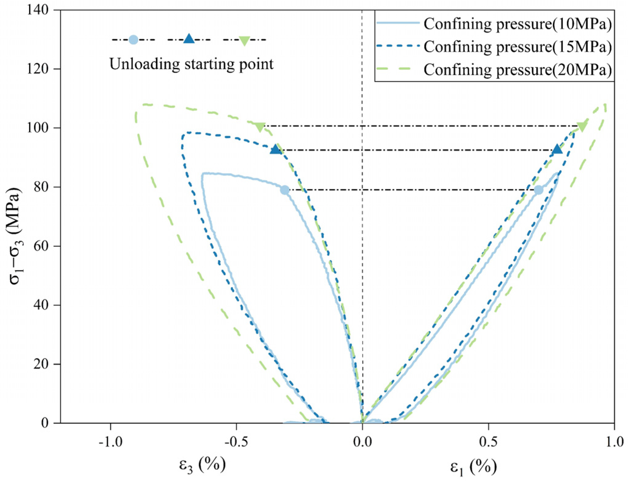
The OA section (as labeled in Figure 6) is the hydrostatic pressure stage with axial and circumferential loading at equal rates to the same initial target value; the AB section is to keep the confining pressure constant and load the axial pressure to 70% of the triaxial compressive strength at a specific confining pressure; the BC section is to keep the axial pressure constant and unload the confining pressure to reach the target value (60% unloading); the CD section indicates unloading the axial pressure to equal the confining pressure; and the DO section unloads the axial circumferential pressure at the same rate simultaneously. According to the above stress path, saturated rock samples were taken for the preparation test of the unloaded-damaged sample under confining pressures of 10 MPa, 15 MPa, and 20 MPa, respectively, and the typical stress-strain curves of rock samples under unloading damage were obtained, as shown in Figure 7.

3.3. Mechanical Characteristics of the Unloaded-Damaged Samples

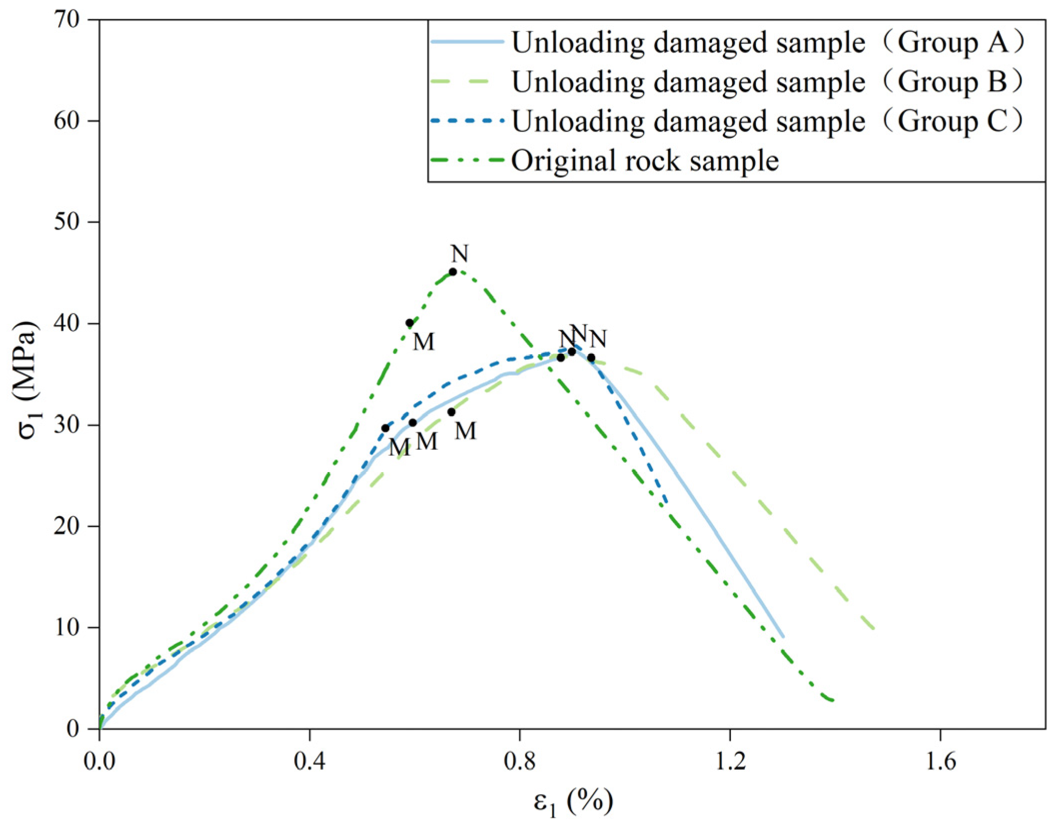
To illustrate the mechanical characteristics of the unloaded-damaged samples, uniaxial loading tests of the unloaded-damaged samples and the original samples were carried out, and the stress-strain curves are shown in Figure 8. Unloaded-damaged samples under different initial confining pressures (10, 15, and 20 MPa) were divided into three groups (groups A, B, and C). The MN section is the stage of microcrack development inside the rock during the loading process (point M is the yield point, and the stress corresponding to point N is the uniaxial strength), and the microcrack development stage of the unloaded-damaged samples is more significant than that of the original samples. The reason is that the microcracks induced by the unloading damage are orthogonal to the confining pressure direction and expand first during the uniaxial loading process, resulting in the yield point shifting down and an accelerated axial strain growth rate and the uniaxial strengths are smaller than those of the original samples. This indicates the feasibility of the above unloading damage test.
The uniaxial strengths of unloaded-damaged samples with different initial confining pressures (10, 15, and 20 MPa) are 37.22, 36.56, and 37.80 MPa, respectively, with approximately the same quantitative values. This indicates that the uniaxial strength of the unloaded-damaged samples is largely independent of the initial confining pressure size, reflecting the reasonableness of the abovementioned unloaded-damage classification criterion by unloading quantity.

4. Freeze-Thaw Test Results and Analysis

4.1. Porosity Variation Characteristics of Unloaded-Damaged Samples after Freeze-Thaw

The freeze-thaw cycling action causes changes in rock microstructure, and the most direct result is an increase in porosity. The process of porosity change with the number of freeze-thaw cycles can directly reflect the evolution of freeze-thaw damage and the use of porosity deformation as the damage variable makes the determination and calculation of freeze-thaw damage more convenient. By measuring the porosity of the unloaded-damaged samples after each freeze-thaw cycle, the average change in porosity with the increase in the number of freeze-thaw cycles was obtained. The average porosity of the unloaded-damaged samples after n and 0 freeze-thaw cycles are set as Pn and P0, respectively. The average porosity change is shown in Equation (3), and the calculation results are shown in Table 1.
Δ P n = P n P 0
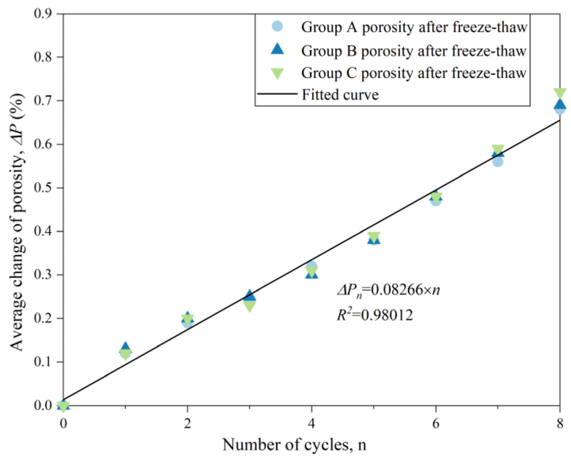
Figure 9 shows that the evolution of the average change in porosity of the three groups of unloaded-damaged samples is roughly the same, and the average change in porosity increases with the increase in the number of freeze-thaw cycles. The main reason is that the three-phase medium (water, ice, and rock) in the rock body has different thermophysical properties. When freezing, the uneven contraction of mineral-particle volume and the expansion of pore water freezing occur, causing the particle boundary and pore wall to be subjected to freeze-swelling force, expanding the pore volume and causing local damage inside the rock sample. When room temperature ablation occurs, the pore ice melts into water, and the freeze-swelling force gradually dissipates, accompanied by the continuous migration of water. After this freeze-thaw cycle, the porosity of the unloaded-damaged sample gradually increases. The freeze-thaw damage inside the rock sample accumulates with the increase in freeze-thaw cycles and develops from local damage to overall damage and even sprouts macroscopic fissures.
The three groups of unloaded-damaged samples have different initial confining pressures, but the average change in porosity with the number of freeze-thaw cycles is approximately the same, indicating that the degree and trend of fine structure deterioration after freeze-thaw cycles are largely the same for unloaded-damaged samples with different initial confining pressures. The unloading quantity is used to define the degree of unloading damage, and the unloading damage state is the same, so the response to freeze-thaw cycles is also largely the same. This shows that the above definition of unloading quantity as the damage classification criterion can distinguish the degree of unloading damage, and the average change of porosity can be used to measure the freeze-thaw deterioration characteristics of unloaded-damaged samples.

4.2. Failure characteristics of Unloaded-Damaged Samples after Freeze-Thaw and Reloading

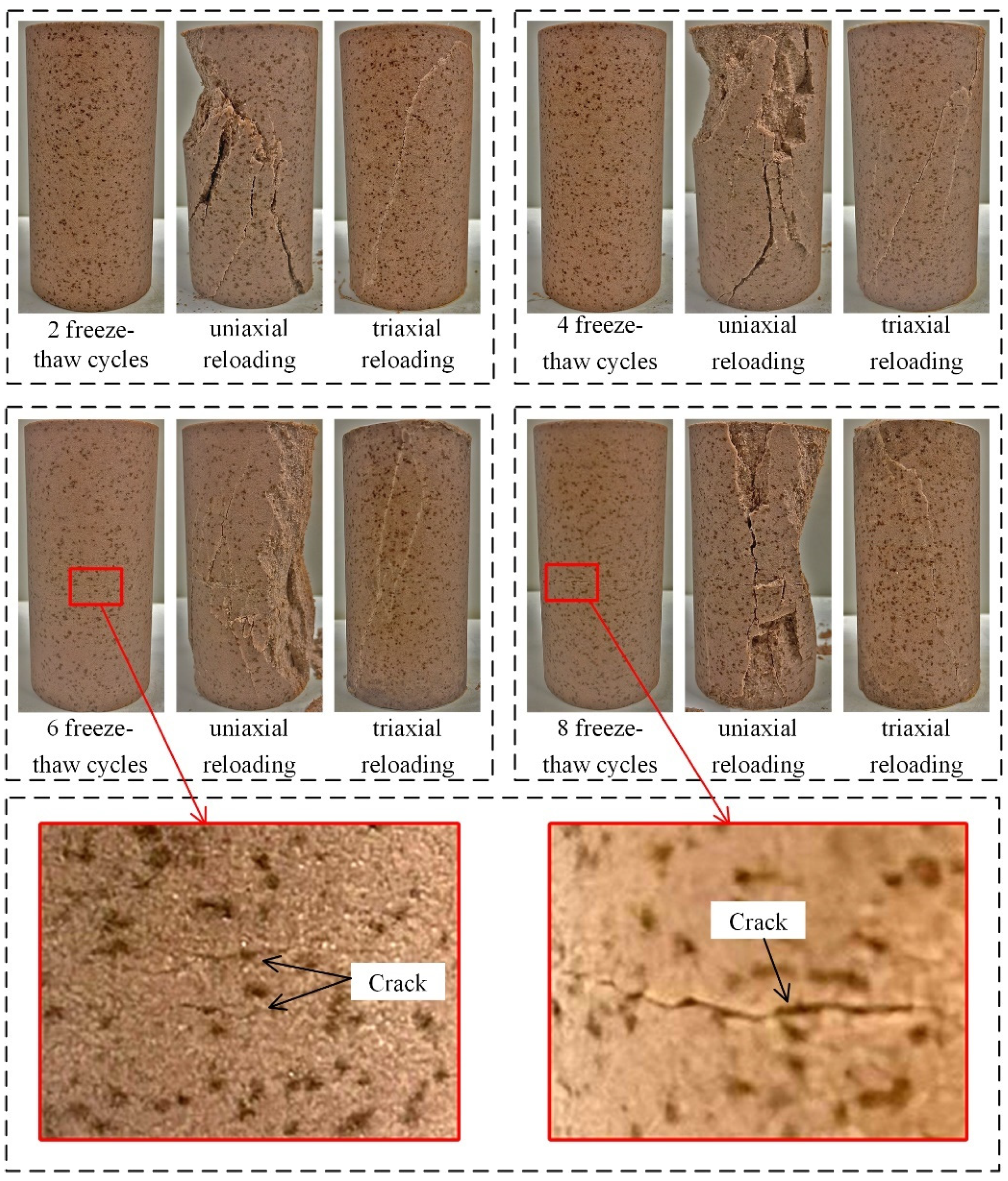
The damage characteristics of the unloaded-damaged samples after two, four, six, and eight freeze-thaw cycles, as well as uniaxial and triaxial reloading, are shown in Figure 10.
  • After two and four freeze-thaw cycles, there is no significant change in the surface appearance of the sample, while after six and eight freeze-thaw cycles, transverse cracks appear on the surface and gradually develop and expand with the increase in the number of freeze-thaw cycles. The freeze-swelling force caused by the freezing of pore water acts on the pore wall, and this action is equivalent to the three-way tensile load on the rock sample. The unloaded-damaged samples are found to be mainly damaged in the axial direction by the apparent freeze-thaw deterioration characteristics, and transverse cracks develop and expand gradually;
  • The uniaxial reloading damage pattern of the unloaded-damaged samples exhibits oblique penetration damage from top to bottom, and the number of ruptured blocks increases with the increase in the number of freeze-thaw cycles, indicating that the cycles trigger the development of internal pore fractures in the unloaded-damaged samples and induce macroscopic uniaxial reloading damage fragmentation;
  • The triaxial reloading damage pattern shows an oblique penetration from the top to the bottom and multiple local damage cracks. The increase in the number of freeze-thaw cycles causes the development of multilinear local crack extension.

4.3. Analysis of Peak Strength Deterioration after Freeze-Thaw and Reloading of Unloaded-Damaged Samples

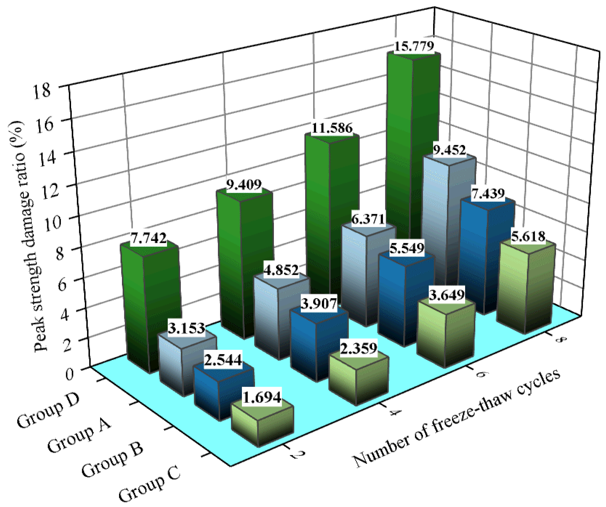
Uniaxial and triaxial reloading tests were conducted on the unloaded-damaged samples for a defined number of freeze-thaw cycles. From the above analysis, it can be seen that the degree of damage of the unloaded-damaged samples and the response to freeze-thaw deterioration are not related to the size of the initial confining pressure. Uniaxial reloading tests after freeze-thaw were carried out using the group A unloaded-damaged samples, and the test results are grouped and named group D. For the perimeter pressure value of the triaxial reload mechanics test, the confining pressure unloading target values (5.8 MPa, 8.4 MPa, and 12.5 MPa) for the preparation of the unloaded-damaged samples are selected and called the unloading residual confining pressure values. The test results are shown in Table 2, and the strength damage rate δ is:
δ = F 0 F n F 0 × 100 %
where F 0 is the peak uniaxial and triaxial reloading strength of the unloaded-damaged sample after 0 freeze-thaw cycles, and F n is the peak uniaxial reload strength of the unloaded-damaged sample after n freeze-thaw cycles.
From Figure 11, it can be seen that the trend in the uniaxial and triaxial reloading peak strength loss rate of the unloaded-damaged samples is more or less the same; that is, the strength loss rate increases gradually with the increase in the number of freeze-thaw cycles. The uniaxial reloading peak strength loss rate of the unloaded-damaged samples is higher than that of triaxial in the overall number of freeze-thaw cycles, and it is controlled by the size of the unloading residual confining pressure, which shows that the larger the value is, the smaller the strength loss rate. The main reason is that the freeze-thaw cycle is partially inhibited by the compression of the annular structure of the rock sample in the hydrostatic pressure loading stage in the triaxial reloading test after freeze-thawing of the unloaded-damaged samples. This weakens the freeze-thaw deterioration effect and leads to a reduction in the peak strength loss rate. The larger the enclosing pressure is, the more obvious the degree of inhibition.
The rock body of the excavation and unloaded zone of a slope in cold regions is in a three-way stress state, and the freeze-thaw cycle erosion induced by the climatic environment of the site aggravates the damage deterioration of the excavation and unloaded rock body. The strength characteristics of the excavation and unloaded rock body are subject to the dual effect of the stress state and freeze-thaw erosion, and the effect of freeze-thaw erosion is influenced by the stress state. Therefore, it is necessary to consider the stress state of the unloaded zone rock when studying the freeze-thaw strength deterioration of the rock body in the unloaded zone of the excavation slope.

5. Freeze-Thaw Strength Decay Model

5.1. Strength Decay Model

The evolution of the average change in porosity with the number of freeze-thaw cycles is approximately the same as the value of the change, which is independent of the initial confining pressure and can be easily determined. A positive relationship exists between the average change in porosity and the number of freeze-thaw cycles, as shown in Figure 9. The average change in porosity and the number of freeze-thaw cycles obey a proportional function.
Δ P n = P n P 0 = k n
where k is the average change in porosity per unit number of freeze-thaw cycles. From Equation (5), we have
n = P n P 0 k = Δ P n k
The strength damage rate of the uniaxial and triaxial reloads after freeze-thawing of the unloaded-damaged samples increases with the number of freeze-thaw cycles and is controlled by the magnitude of the unloading residual confining pressure value. Mutluturk [33] first proposed describing the loss in uniaxial strength of rocks due to freeze-thaw action using the classical exponential decay model (see Equation (7)). Based on the correlation between the number of freeze-thaw cycles and strength decay, the loss in uniaxial strength is extended to loss in triaxial strength, and the decay constant is modified by fitting the experimental data to introduce the value of unloading saving residual confining pressure as a parameter, which in turn reflects the influence of the stress state on the freeze-thaw strength decay of unloaded-damaged samples.
F n = F 0 e λ n
where F n and F 0 are the uniaxial strength after n freeze-thaw cycles and before freeze-thawing, respectively, λ is the decay constant, and n is the number of freeze-thaw cycles.
Substituting Equation (6) into Equation (7) yields
F n = F 0 e λ k Δ P n
The test data fitting was used to first identify the parameters of the decay constant, introducing the value of the unloading residual confining pressure as a parameter, and then the average change in porosity per unit number of freeze-thaw cycles was corrected by fitting.

5.2. Parameter Determination

First, based on the above generalization idea of the exponential decay model, the magnitude of the unloading residual confining pressure value is determined. The exponential function model is selected to fit the unloaded-damaged samples of groups A, B, C, and D under the action of freeze-thaw cycles in terms of the peak strength versus the number of freeze-thaw cycles. The results are shown in Figure 12, all of which indicate a good correlation between the unloaded-damaged samples reload peak strengths after freeze-thawing (both uniaxial and triaxial) and the number of freeze-thaw cycles.
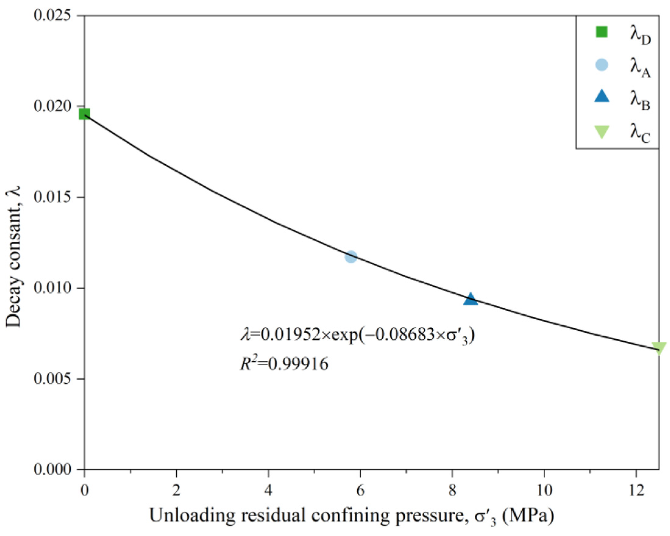
Table 3 lists the specific values of the four groups of unloaded-damaged sample fitting parameters. F0 is the uniaxial and triaxial peak strength before freeze-thaw of the unloaded-damaged samples, and its value can be directly obtained from the mechanical strength test of the unloaded-damaged samples. To correct the decay constant, the exponential function model is used to fit the decay constant and the value of the unloading residual confining pressure, as shown in Figure 13. The correlation constant R2 = 0.999, and the correction results are shown in Equation (9).
λ = 0.01952 × exp ( 0.08683 × σ 3 )
The average change in porosity of the unloaded-damaged samples with the number of freeze-thaw cycles at different initial confining pressures is largely the same, and the values are approximately equal. Therefore, the average change in porosity of the unloaded-damaged samples in the three groups can be linearly fitted with the number of freeze-thaw cycles according to Equation (5). The results are shown in Figure 14, with the correlation constant R2 = 0.98, which is a good fit. The value of k = 0.08266, which is the microstructural deterioration constant after freeze-thaw cycling for the unloaded-damaged samples; the results are shown in Equation (10).
Δ P n = 0.08266 × n
Substituting Equations (9) and (10) into Equation (8), the relationship between the peak uniaxial and triaxial reload strength and the average change in porosity after freezing and thawing of the unloaded-damaged samples is obtained, as shown in Equation (11).
F n = F 0 e 0.01952 × exp ( 0.08683 × σ 3 ) 0.08266 Δ P n
where F n and F 0 are the peak uniaxial and triaxial reload strengths of the unloaded damaged sample after n freeze-thaw cycles and before freeze-thawing, respectively, σ 3 is the unloading residual confining pressure value, and Δ P n is the average change in porosity.

5.3. Verification

To verify the correctness and reasonableness of the above freeze-thaw strength decay model for unloaded-damaged samples, test data were used for verification. Based on the average change in porosity before and after freeze-thaw cycles of the unloaded-damaged samples provided in Table 1, and the peak uniaxial and triaxial reload strengths before freeze-thaw cycles in Table 2, the calculated values of the strength decay model were obtained by substituting into Equation (11) and compared with the experimental results, as shown in Table 4.
The calculated values of uniaxial and triaxial reloading peak strength of the unloaded-damaged samples after freeze-thawing are largely consistent with the tested values. On the one hand, this shows that the freeze-thaw strength decay model established by the unloaded-damaged samples can better reflect the strength decay after freeze-thaw by using the average change in porosity before and after freeze-thaw, considering the effect of unloading residual confining pressure. On the other hand, the number of freeze-thaw cycles is not included in the model, and the freeze-thaw strength of sample is only related to the change in porosity after freeze-thaw and the magnitude of the confining pressure at the time of re-load, so the easily accessible change in porosity after freeze-thaw can be measured without conducting mechanical tests on the unloaded damaged sample after freeze-thaw, i.e., without damaging the rock samples, and combined with Equation (11) to predict the freeze-thaw strength of the unloaded-damaged samples under the action of different unloading residual confining pressure.

6. Conclusions

In this paper, an unloading-damage test was carried out on a yellow sandstone sample with 60% unloading quantity under three types of confining pressure, and freeze-thaw mechanical tests were performed on the resulting unloaded-damaged samples. A freeze-thaw strength decay model based on the average change in porosity before and after freeze-thawing and the ability to consider the effect of unloading residual confining pressure was established. The model parameters were identified and verified by fitting the test data, and the following conclusions were finally obtained.
  • In the process of unloading sandstone under different initial confining pressures, the evolution process of the amount of unloading on the deformation response of the rock sample is largely the same. Unloading quantities of 60% and 90% were used as the dividing points to create three stages: the slow section, uniform section, and accelerated section. A 60% unloading quantity is the dividing point for the opening and continuous expansion of microfractures induced by unloading inside the rock sample. The uniaxial strength of the unloaded-damaged samples under different initial confining pressures with 60% unloading is roughly the same, which is smaller than the uniaxial strength of the original sample, reflecting the feasibility and reasonableness of the abovementioned unloading quantity as the classification criterion of unloading damage and the unloading-damage test;
  • The initial confining pressure of the three groups of unloaded-damaged samples is different, while the change in porosity with the number of freeze-thaw cycles and the value of change after freezing-thawing are constant across different initial confining pressures. This indicates that the degree and trend of freeze-thaw deterioration of unloaded-damaged samples with 60% unloading are largely the same, independent of the initial envelope pressure, so the average change in porosity can be used to measure the freeze-thaw deterioration of the unloaded-damaged samples;
  • The peak strength damage rate of the unloaded-damaged samples after freeze-thaw reloading (both uniaxial and triaxial) increases with the increase in the number of freeze-thaw cycles. The unloading residual pressure value inhibits the increase; a larger value of unloading residual pressure leads to a more obvious degree of inhibition;
  • Using the extended exponential attenuation model, the decay constant was modified by fitting the experimental data. The value of unloading residual confining pressure was introduced as the decay parameter and the freeze-thaw strength decay model was established with the easily determined average change in porosity. The values calculated by the model are largely consistent with the tested values. It is verified that the proposed model can reflect the decay of freeze-thaw strength using the average change in porosity after freeze-thaw cycles and can also consider the effect of unloading residual confining pressure. This reveals the micromechanical behavior induced by microstructure damage after freeze-thaw cycles of unloaded-damaged samples and predicts the decay in freeze-thaw strength. This provides some guidance for freeze-thaw hazard prediction of excavation and unloaded rock in cold regions.

Author Contributions

Conceptualization, X.C., W.D., L.C., B.M. and S.G.; Methodology, X.C., W.D., L.C., B.M. and H.J.; Validation, B.M. and S.G.; Formal analysis, L.C., B.M., H.J. and W.W.; Investigation, W.W.; Data curation, W.D.; Writing original draft, W.D. and S.G.; Writing review & editing, X.C., L.C., B.M., S.G. and W.W.; Supervision, X.C.; Project administration, X.C., W.D. and H.J.; Funding acquisition, X.C. All authors have read and agreed to the published version of the manuscript.

Funding

This research was supported by the National Natural Science Foundation of China (Grant No. U1965107 and No. 51979218) and the Natural Science Foundation of Shaanxi Province (Grant No. 2018JM5118).

Institutional Review Board Statement

Not applicable.

Informed Consent Statement

Not applicable.

Data Availability Statement

The dataset used to support the findings of this study is available from the corresponding author upon request.

Conflicts of Interest

The authors declare that there is no conflict of interest.

References

  1. Deprez, M.; De Kock, T.; De Schutter, G.; Cnudde, V. A review on freeze-thaw action and weathering of rocks. Earth-Sci. Rev. 2020, 203, 103143. [Google Scholar] [CrossRef]
  2. Li, J.; Wang, L. Theories of Unloading Rock Mass Mechanics and Its Engineering Practice; Science Press: Beijing, China, 2016. [Google Scholar]
  3. Huang, R. Mechanisms of large-scale landslides in China. Bull. Eng. Geol. Environ. 2011, 71, 161–170. [Google Scholar] [CrossRef]
  4. Deng, H.; Wang, Z.; Li, J.; Jiang, Q.; Zhang, H. Effect of unloading rate and pore water pressure on mechanical properties of sandstone. Chin. J. Geotech. Eng. 2017, 39, 1976–1983. [Google Scholar] [CrossRef]
  5. Ren, H.; Zhu, Y.; Wang, P.; Yu, W.; Li, P.; Zhang, Y. Experimental study on mechanical characteristics of unloaded damaged white sandstone before peak. Arab. J. Geosci. 2020, 13, 878. [Google Scholar] [CrossRef]
  6. Wang, S.; Wang, H.; Xu, W.; Qian, W. Investigation on mechanical behaviour of dacite under loading and unloading conditions. Géotech. Lett. 2019, 9, 130–135. [Google Scholar] [CrossRef]
  7. Meng, L.; Li, T.; Xu, J.; Chen, G.; Ma, H.; Yin, H. Deformation and failure mechanism of phyllite under the effects of THM coupling and unloading. J. Mt. Sci. 2012, 9, 788–797. [Google Scholar] [CrossRef]
  8. Li, X.-B.; Chen, Z.-H.; Weng, L.; Li, C.-J. Unloading responses of pre-flawed rock specimens under different unloading rates. Trans. Nonferrous Met. Soc. China 2019, 29, 1516–1526. [Google Scholar] [CrossRef]
  9. Xie, H.Q.; He, C.H. Study of the unloading characteristics of a rock mass using the triaxial test and damage mechanics. Int. J. Rock Mech. Min. Sci. 2004, 41, 74–80. [Google Scholar] [CrossRef]
  10. Feng, F.; Chen, S.; Wang, Y.; Huang, W.; Han, Z. Cracking mechanism and strength criteria evaluation of granite affected by intermediate principal stresses subjected to unloading stress state. Int. J. Rock Mech. Min. Sci. 2021, 143, 104783. [Google Scholar] [CrossRef]
  11. Wang, C.; Zhou, B.; Li, C.; Cao, C.; Sui, Q.; Zhao, G.; Yu, W.; Chen, Z.; Wang, Y.; Liu, B.; et al. Experimental investigation on the spatio-temporal-energy evolution pattern of limestone fracture using acoustic emission monitoring. J. Appl. Geophys. 2022, 206, 104787. [Google Scholar] [CrossRef]
  12. Wang, C.; Liu, Y.; Hou, X.; Elmo, D. Investigation of the spatial distribution pattern of 3D microcracks in single-cracked breakage. Int. J. Rock Mech. Min. Sci. 2022, 154, 105126. [Google Scholar] [CrossRef]
  13. Qiu, S.-L.; Feng, X.-T.; Xiao, J.-Q.; Zhang, C.-Q. An Experimental Study on the Pre-Peak Unloading Damage Evolution of Marble. Rock Mech. Rock Eng. 2013, 47, 401–419. [Google Scholar] [CrossRef]
  14. Li, D.; Sun, Z.; Xie, T.; Li, X.; Ranjith, P.G. Energy evolution characteristics of hard rock during triaxial failure with different loading and unloading paths. Eng. Geol. 2017, 228, 270–281. [Google Scholar] [CrossRef]
  15. Chen, X.; Tang, C.-A.; Yu, J.; Zhou, J.-F.; Cai, Y.-Y. Experimental investigation on deformation characteristics and permeability evolution of rock under confining pressure unloading conditions. J. Cent. South Univ. 2018, 25, 1987–2001. [Google Scholar] [CrossRef]
  16. Zhao, E.P.; Lu, B.; Jia, X.B. Disscusion on the Unloading—Seepage Coupled Model of Damaged Rock. Aer. Adv. Eng. Res. 2016, 75, 31–36. [Google Scholar] [CrossRef] [Green Version]
  17. Zhou, K.; Liu, T.; Hu, Z. Exploration of damage evolution in marble due to lateral unloading using nuclear magnetic resonance. Eng. Geol. 2018, 244, 75–85. [Google Scholar] [CrossRef]
  18. Weng, L.; Wu, Z.; Liu, Q. Evaluating Damage and Microcracking Behavior of Granite Using NMR Testing under Different Levels of Unconfined Compression. Int. J. Geomech. 2019, 19, 4018186. [Google Scholar] [CrossRef]
  19. Deng, H.; Assefa, E.; Xu, X.; Luo, Z.; Li, J.; Jiang, Q. Study on the Time-lag Failure of Sandstone with Different Degrees of Unloading Damage. Period. Polytech. Civ. Eng. 2019, 63, 206–214. [Google Scholar] [CrossRef] [Green Version]
  20. Manouchehrian, A.; Cai, M. Simulation of unstable rock failure under unloading conditions. Can. Geotech. J. 2016, 53, 22–34. [Google Scholar] [CrossRef]
  21. Zhang, H.; Wang, L.; Li, J.; Deng, H.; Xu, X.; Chen, X. Mechanical Properties of Sandstones under Initial Unloading Damage. Adv. Civ. Eng. 2021, 2021, 6615846. [Google Scholar] [CrossRef]
  22. Zhu, Z.; Yu, L.; Li, J.; Su, H.; Zhang, Z.; Zhang, J. Research on acoustic emission characteristics of marble damaged by pre-peak unloading. IOP Conf. Ser. Earth Environ. Sci. 2020, 570, 32050. [Google Scholar] [CrossRef]
  23. Liang, Z.; Yu, Z.; Guo, L.; Huang, S.; Qin, N.; Wen, Z. Evaluation of white sandstone mechanical behaviour and the energy evolution of prepeak unloading damage. Sci. Rep. 2022, 12, 2793. [Google Scholar] [CrossRef] [PubMed]
  24. Xu, G.; Liu, Q. Analysis of mechanism of rock failure due to freeze-thaw cycling and mechanical testing study on frozen-thawed rocks. Chin. J. Rock Mech. Eng. 2005, 24, 17. [Google Scholar] [CrossRef]
  25. Wang, L.; Jiang, Z.; Li, J.; Tang, K.; Jin, J. The bedding sandstone unloading mechanical properties experimental study in the freeze-thaw cycle conditions. J. Glaciol. Geocryol. 2016, 38, 4. [Google Scholar] [CrossRef]
  26. Mahanta, B.; Tripathy, A.; Vishal, V.; Singh, T.N.; Ranjith, P.G. Effects of strain rate on fracture toughness and energy release rate of gas shales. Eng. Geol. 2017, 218, 39–49. [Google Scholar] [CrossRef]
  27. Martins, L.; Vasconcelos, G.; Lourenço, P.B.; Palha, C. Influence of the Freeze-Thaw Cycles on the Physical and Mechanical Properties of Granites. J. Mater. Civ. Eng. 2016, 28, 5. [Google Scholar] [CrossRef] [Green Version]
  28. Li, Y.; Zhai, Y.; Meng, F.; Zhang, Y. Study on the Influence of Freeze-Thaw Weathering on the Mechanical Properties of Huashan Granite Strength. Rock Mech. Rock Eng. 2021, 54, 4741–4753. [Google Scholar] [CrossRef]
  29. Gao, J.; Xu, C.; Xi, Y.; Fan, L. Degradation of Mechanical Behavior of Sandstone under Freeze-Thaw Conditions with Different Low Temperatures. Appl. Sci. 2021, 11, 10653. [Google Scholar] [CrossRef]
  30. Huang, S.; Yu, S.; Ye, Y.; Ye, Z.; Cheng, A. Pore structure change and physico-mechanical properties deterioration of sandstone suffering freeze-thaw actions. Constr. Build. Mater. 2022, 330, 127200. [Google Scholar] [CrossRef]
  31. Li, X.; Peng, J.; Xie, Y.; Li, Q.; Zhou, T.; Wang, J.; Zheng, W.; Ao, S. Influence of High-Temperature Treatment on Strength and Failure Behaviors of a Quartz-Rich Sandstone under True Triaxial Condition. Lithosphere 2022, 2022, 3086647. [Google Scholar] [CrossRef]
  32. Kolay, E. Modeling the effect of freezing and thawing for sedimentary rocks. Environ. Earth Sci. 2016, 75, 210. [Google Scholar] [CrossRef]
  33. Mutlutürk, M.; Altindag, R.; Türk, G. A decay function model for the integrity loss of rock when subjected to recurrent cycles of freezing-thawing and heating-cooling. Int. J. Rock Mech. Min. Sci. 2004, 41, 237–244. [Google Scholar] [CrossRef]
  34. Aral, İ.F.; Boy, R.; Dinçer, A.R. Effects of freeze-thawing cycles on the physical and mechanical properties of basaltic and dolomitic rocks evaluated with a decay function model. Bull. Eng. Geol. Environ. 2021, 80, 2955–2962. [Google Scholar] [CrossRef]
  35. Jamshidi, A.; Nikudel, M.R.; Khamehchiyan, M. Evaluation of the durability of Gerdoee travertine after freeze-thaw cycles in fresh water and sodium sulfate solution by decay function models. Eng. Geol. 2016, 202, 36–43. [Google Scholar] [CrossRef]
  36. Eslami, J.; Walbert, C.; Beaucour, A.-L.; Bourges, A.; Noumowe, A. Influence of physical and mechanical properties on the durability of limestone subjected to freeze-thaw cycles. Constr. Build. Mater. 2018, 162, 420–429. [Google Scholar] [CrossRef]
  37. Wang, P.; Xu, J.; Liu, S.; Liu, S.; Wang, H. A prediction model for the dynamic mechanical degradation of sedimentary rock after a long-term freeze-thaw weathering: Considering the strain-rate effect. Cold Reg. Sci. Technol. 2016, 131, 16–23. [Google Scholar] [CrossRef] [Green Version]
  38. Gao, F.; Xiong, X.; Zhou, K.; Li, J.-I.; Wenchao, S. Strength deterioration model of saturated sandstone under freeze-thaw cycles. Rock Soil Mech. 2019, 40, 3. [Google Scholar] [CrossRef]
  39. Xu, S.; Li, N.; Wang, X.; Xu, G.; Yuan, K.; Tian, Y.; Wang, L. Damage test and degradation model of saturated sandstone due to cyclic freezing and thawing of rock slopes of open-pit coal mine. Chin. J. Rock Mech. Eng. 2016, 35, 12. [Google Scholar] [CrossRef]
  40. Mousavi, S.Z.S.; Tavakoli, H.; Moarefvand, P.; Rezaei, M. Micro-structural, petro-graphical and mechanical studies of schist rocks under the freezing-thawing cycles. Cold Reg. Sci. Technol. 2020, 174, 103039. [Google Scholar] [CrossRef]
  41. Li, J.-L.; Zhou, K.-P.; Liu, W.-J.; Deng, H.-W. NMR research on deterioration characteristics of microscopic structure of sandstones in freeze-thaw cycles. Trans. Nonferrous Met. Soc. China 2016, 26, 2997–3003. [Google Scholar] [CrossRef]
  42. Wang, Y.; Han, J.Q.; Li, C.H. Acoustic emission and CT investigation on fracture evolution of granite containing two flaws subjected to freeze-thaw and cyclic uniaxial increasing-amplitude loading conditions. Constr. Build. Mater. 2020, 260, 119769. [Google Scholar] [CrossRef]
  43. Deng, H.; Zhang, H.; Li, J.; Wang, C.; Zhang, Y.; Hu, Y. Effect of water-rock interaction on unloading mechanical properties and microstructure of sandstone. Rock Soil Mech. 2018, 39, 2344–2352. [Google Scholar] [CrossRef]
  44. Qiu, S.; Feng, X.; Zhang, C.; Yang, J. Experimental research on mechanical properties of deep marble under different initial damage levels and unloading paths. Chin. J. Rock Mech. Eng. 2012, 31, 8. [Google Scholar] [CrossRef]
  45. Chen, X.; Chen, L.; Ma, B.; Zhang, X.; Du, W.; Wang, X.; Yang, C. Mechanical-characteristic evaluation of excavation unloading rock mass subject to high-temperature conditions. Eng. Fail. Anal. 2021, 130, 105757. [Google Scholar] [CrossRef]
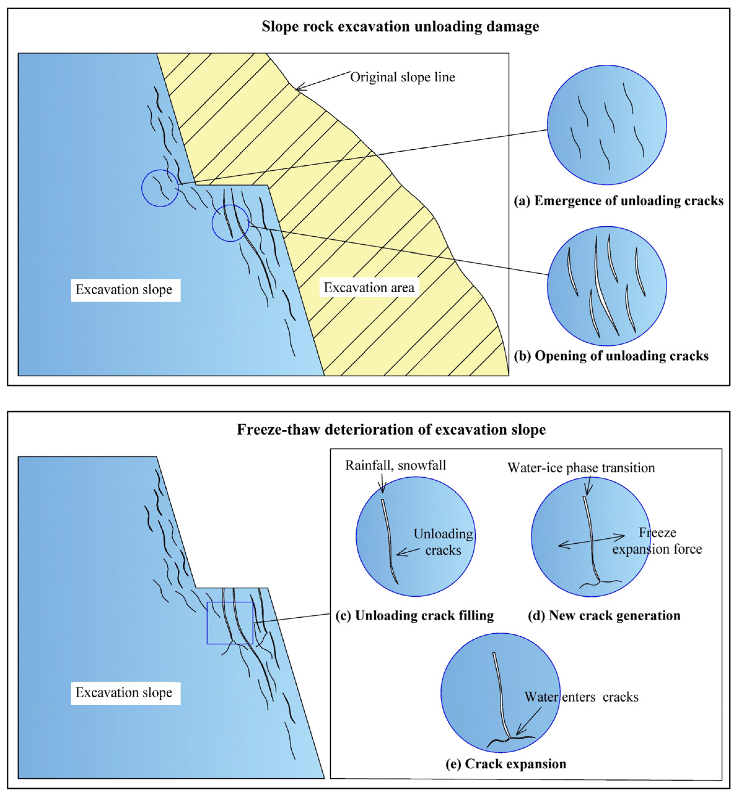
Figure 1. Schematic diagram of the successive effects of slope excavation unloading and freeze-thaw deterioration.
Applsci 12 12205 g001
Figure 2. Homemade rock freezing and thawing jig.
Applsci 12 12205 g002
Figure 3. Schematic diagram of temperature variation in the freeze-thaw cycle test.
Applsci 12 12205 g003
Figure 4. Triaxial unloading test stress-strain curve.
Applsci 12 12205 g004
Figure 5. The relationship between the unloading quantity and the strain confining pressure increment ratio. (a) Axial strain confining pressure increment ratio. (b) Circumferential strain confining pressure increment ratio.
Applsci 12 12205 g005
Figure 6. Description of stress paths in the unloading-damaged test.
Applsci 12 12205 g006
Figure 7. Sample unloading damage stress-strain curve.
Applsci 12 12205 g007
Figure 8. Uniaxially loaded stress-strain curves of unloaded-damaged samples and original samples.
Applsci 12 12205 g008
Figure 9. The relationship between the number of freeze-thaw cycles and the average change in porosity.
Applsci 12 12205 g009
Figure 10. Damage characteristics of the unloaded-damaged samples after freeze-thaw cycles as well as uniaxial and triaxial reloading.
Applsci 12 12205 g010
Figure 11. Relationship between the number of freeze-thaw cycles and the peak strength damage rate.
Applsci 12 12205 g011
Figure 12. Peak strength of unloaded-damaged samples after freeze-thaw. (a) Uniaxial reloading. (b) Triaxial reloading.
Applsci 12 12205 g012
Figure 13. The relationship between the unloading residual confining pressure and the decay constant.
Applsci 12 12205 g013
Figure 14. Relationship between the number of freeze-thaw cycles and the average change in porosity.
Applsci 12 12205 g014
Table 1. Average change in porosity after freeze-thaw cycles for three groups of unloaded-damaged samples.
Number of Freeze-Thaw CyclesAverage Change of Porosity (%)
Group AGroup BGroup C
00.000.000.00
10.120.130.12
20.190.200.20
30.240.250.23
40.320.300.31
50.380.380.39
60.470.480.48
70.560.580.59
80.680.690.72
Table 2. Unloaded-damaged samples uniaxial and triaxial reloading peak strength.
Number of Freeze-Thaw CyclesTriaxial Reloading TestUniaxial Reloading Test
Group A
Peak Strength (MPa)
Strength Damage Rate (%)Group B
Peak Strength (MPa)
Strength Damage Rate (%)Group C
Peak Strength (MPa)
Strength Damage Rate (%)Group D
Peak Strength (MPa)
Strength Damage Rate (%)
0110.660.000125.410.000145.790.00037.200.000
2107.173.153122.222.544143.321.69434.327.742
4105.294.853120.513.907142.352.35933.709.409
6103.616.371118.455.549140.473.64932.8911.586
8100.109.452116.087.439137.605.61831.3315.779
Table 3. Fitting parameter values of freeze-thaw number and peak strength of the unloaded-damaged samples.
Fitting ParameterGroup AGroup BGroup CGroup D
F0110.35915125.06573145.7730236.59078
λ0.011710.009310.006770.01957
Table 4. Calculated and tested values of the peak strength decay model for reloading after freeze-thaw cycles for four groups of unloaded-damaged samples.
Average Change of Porosity (%)Group A
Reloading Peak Strength (MPa)
Group B
Reloading Peak Strength (MPa)
Group C
Reloading Peak Strength (MPa)
Group D
Reloading Peak Strength (MPa)
Calculated ValuesTested ValuesCalculated ValuesTested ValuesCalculated ValuesTested ValuesCalculated ValuesTested Values
0.19107.672107.17122.725122.22143.628143.3235.56834.32
0.31105.827105.29121.059120.51142.279142.3534.57433.70
0.47103.416103.61118.873118.45140.500140.4733.29232.89
0.69100.190100.10115.932116.08138.091137.6031.60731.33
Publisher’s Note: MDPI stays neutral with regard to jurisdictional claims in published maps and institutional affiliations.