
Improvement of the Wear Resistance of Circular Saws Used in the First Transformation of Wood through the Utilization of Variable Engineered Micro-Geometry Performed on PVD-Coated WC-Co Tips

 , ,
, ,
Abstract
:1. Introduction
2. Materials and Methods
2.1. Coating Deposition Technique
2.2. Coating Characterization Methods
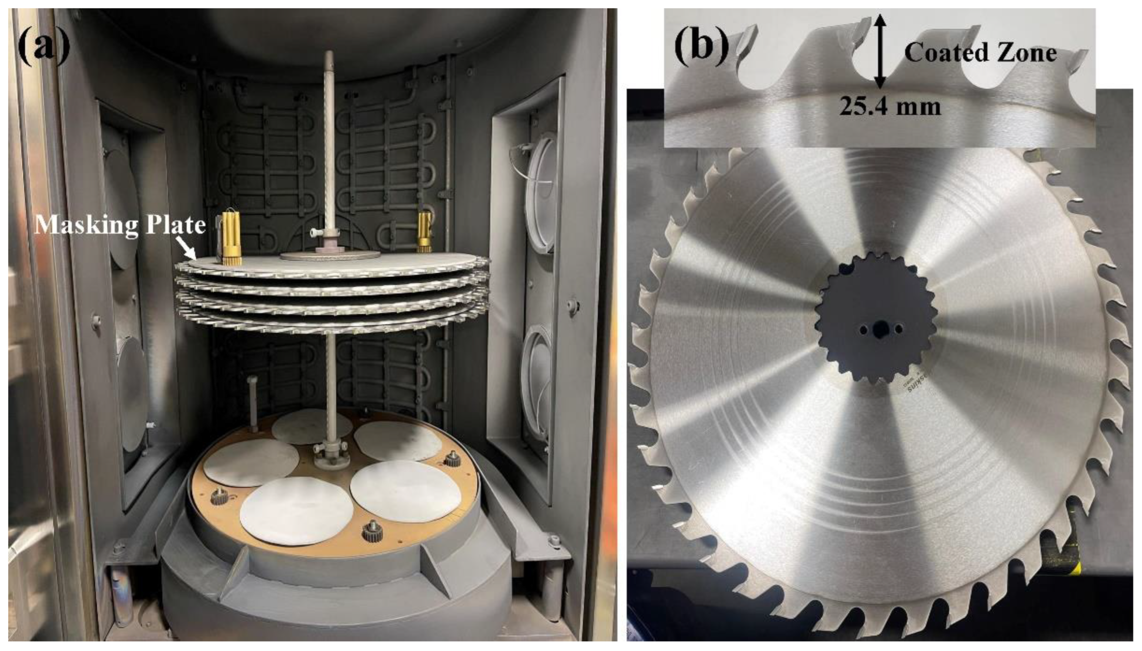
2.3. Coating Deposition on Circular Saws
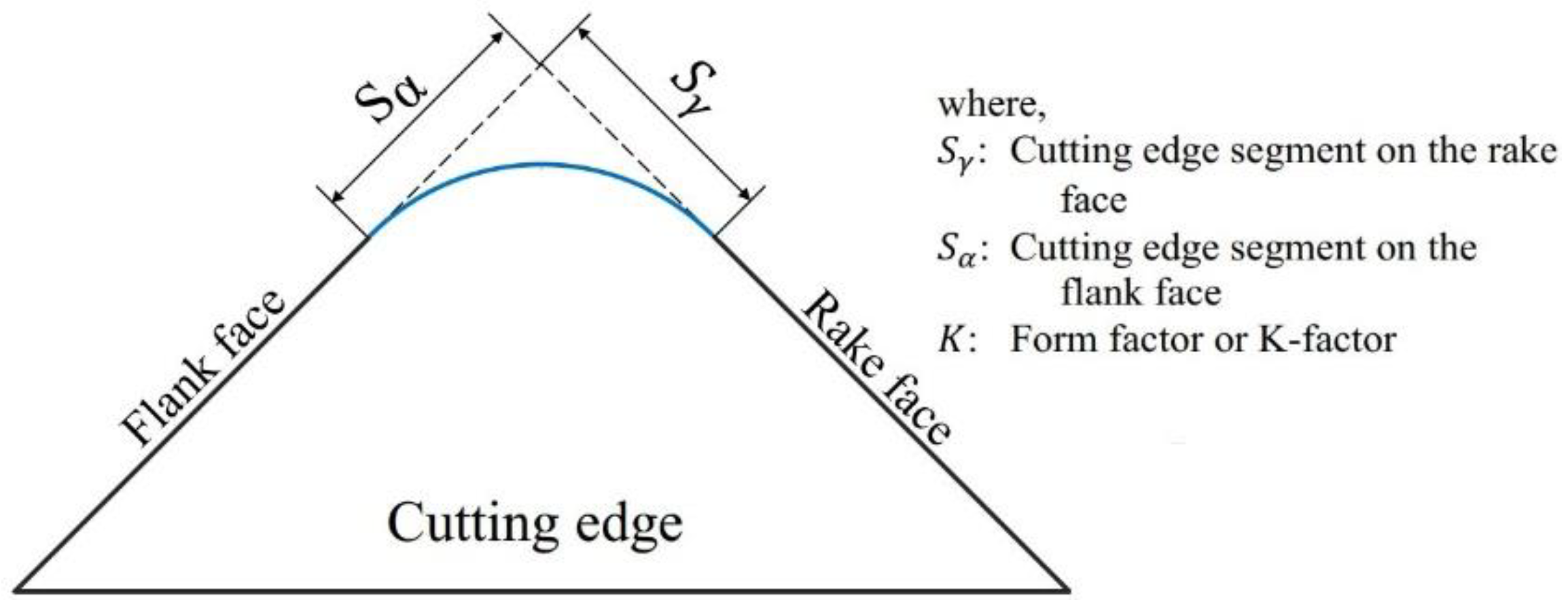
2.4. Variable Engineered Micro-Geometry of the Cutting Edges of Saws
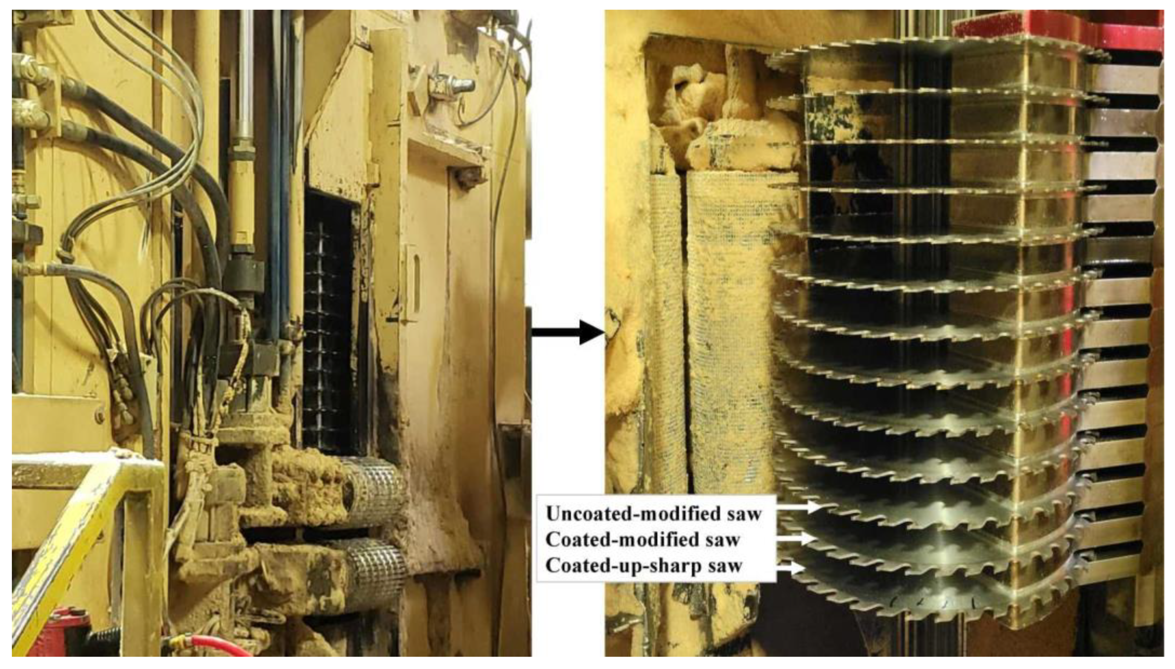
2.5. Industrial Tests
3. Results and Discussion
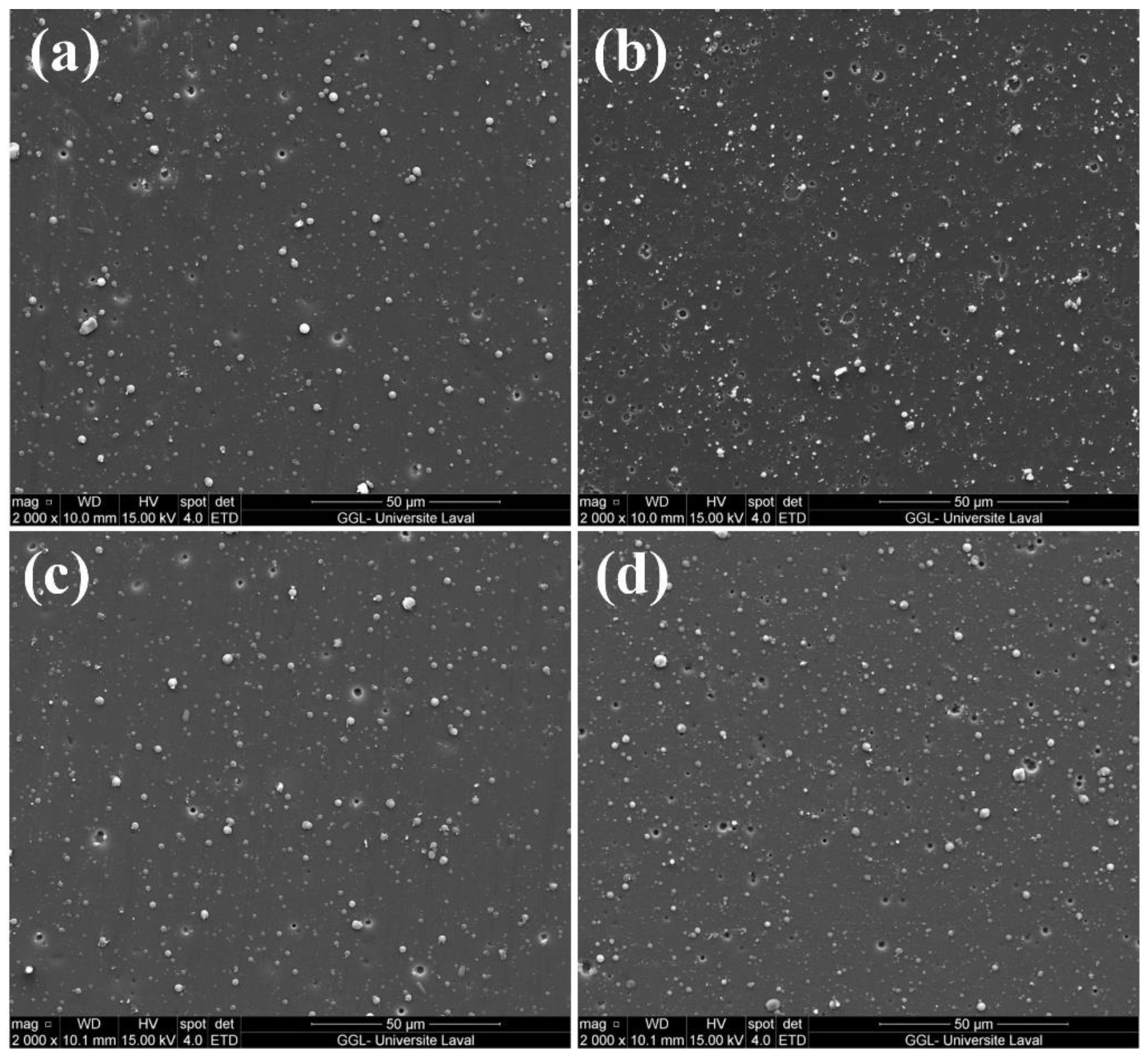
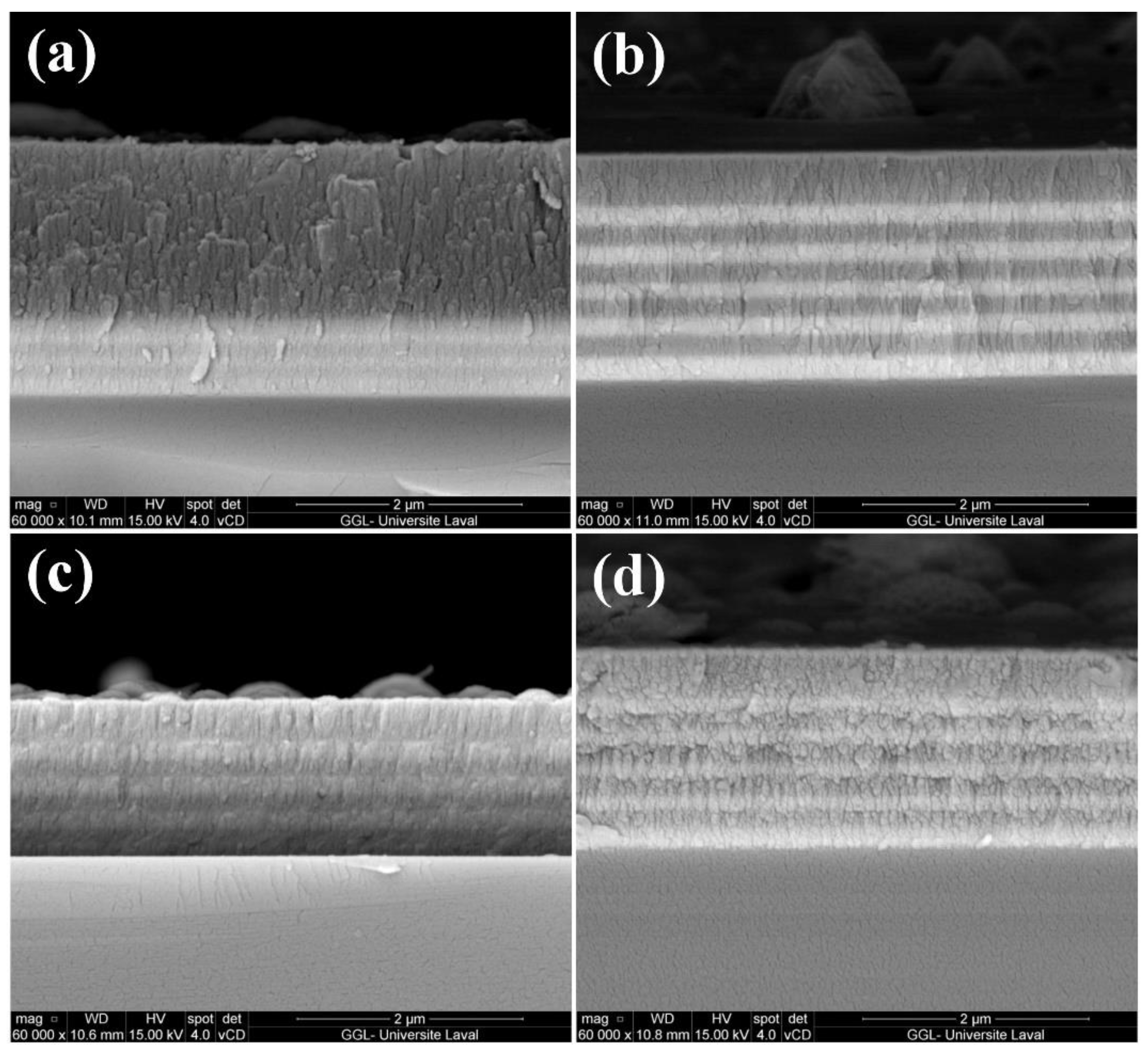
3.1. General Description of Deposited Coatings
3.2. Adhesion Strength
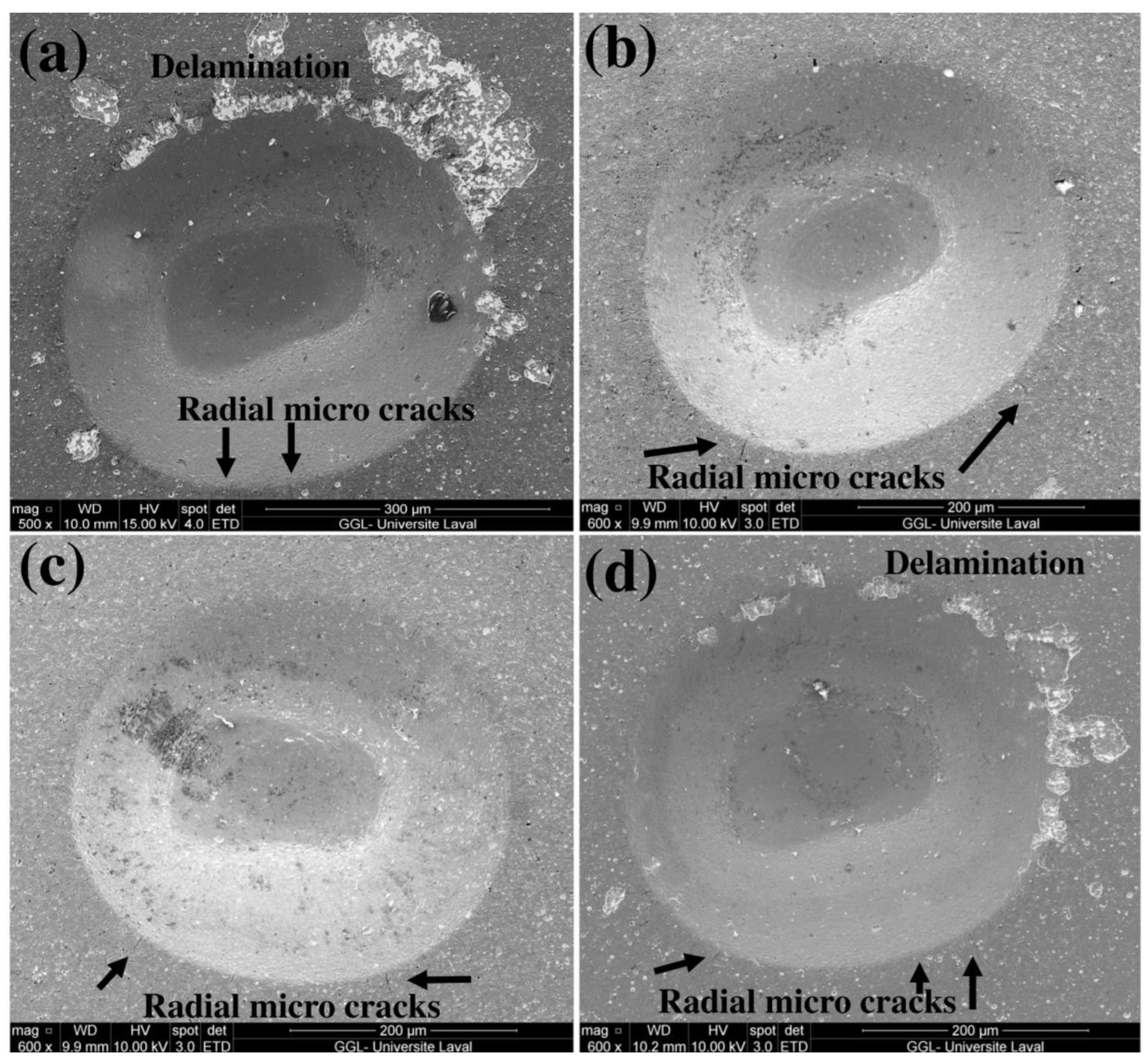
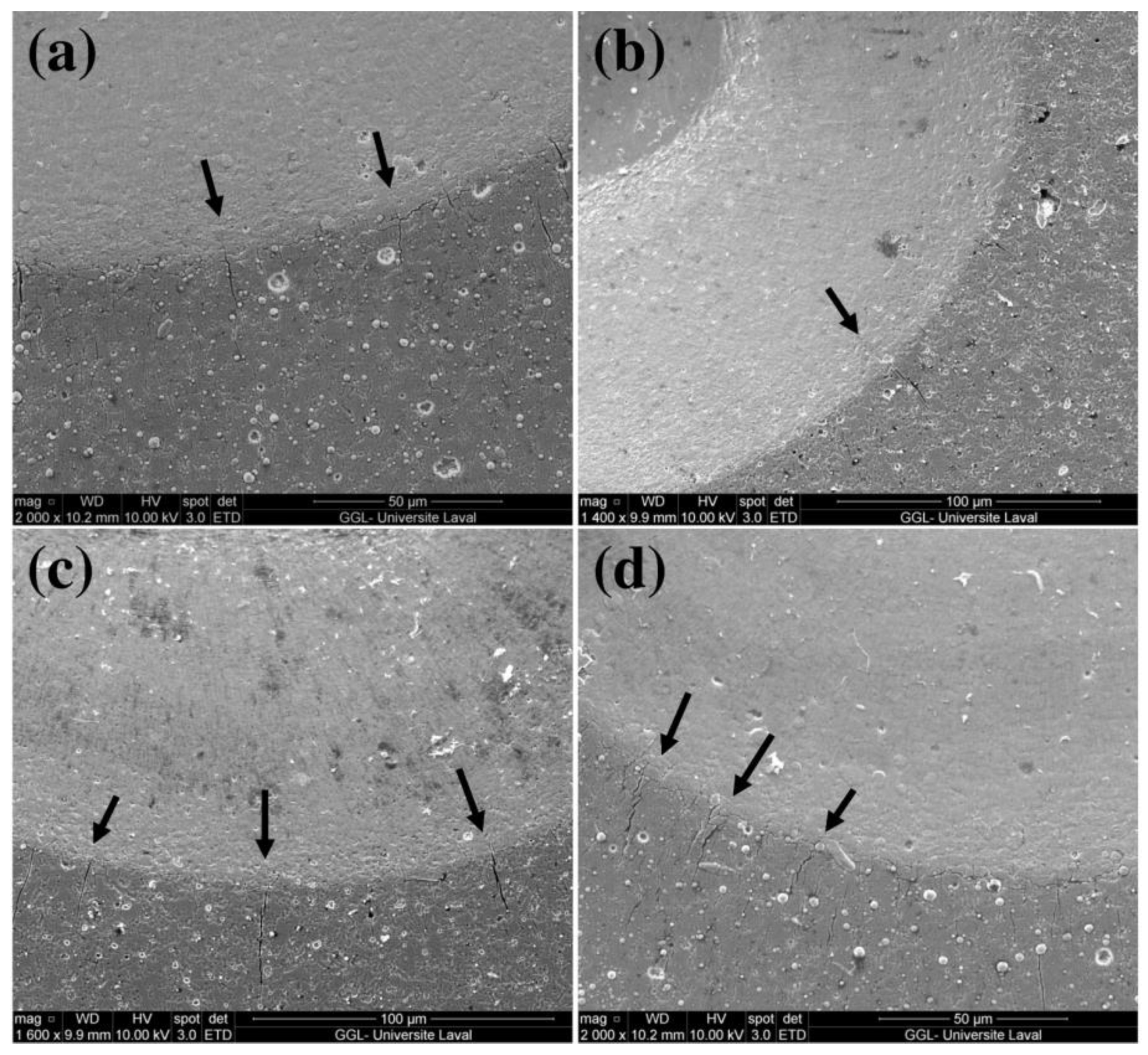
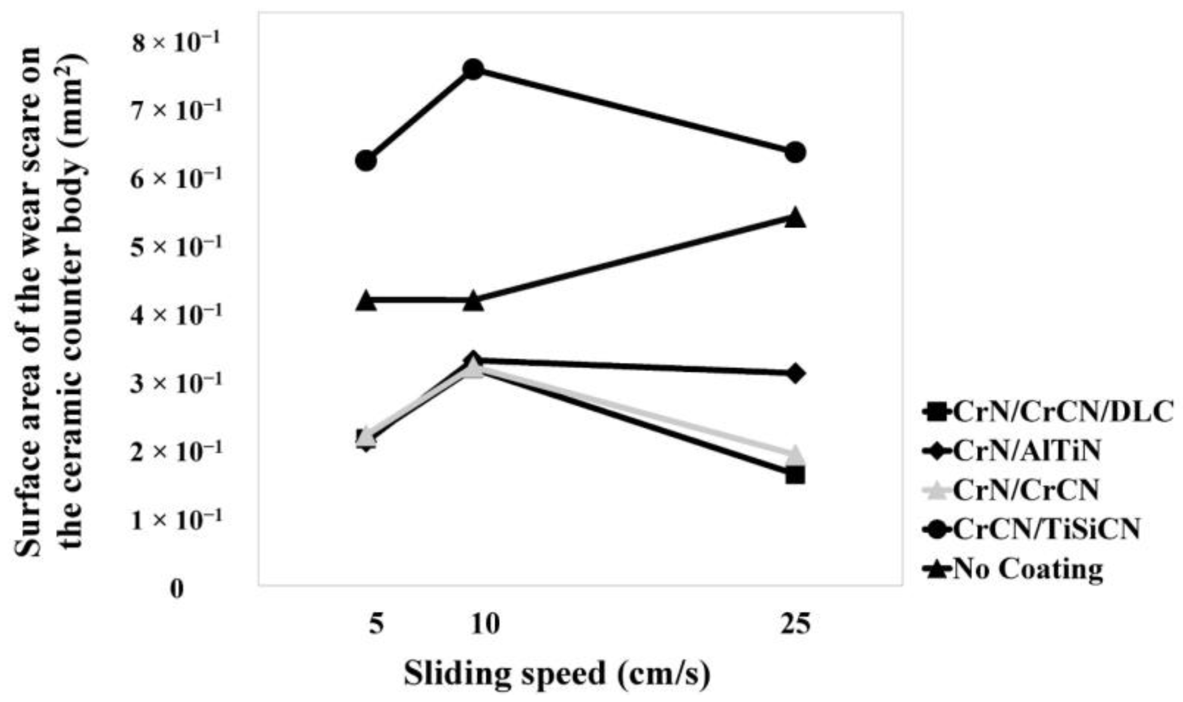
3.3. Tribological Properties
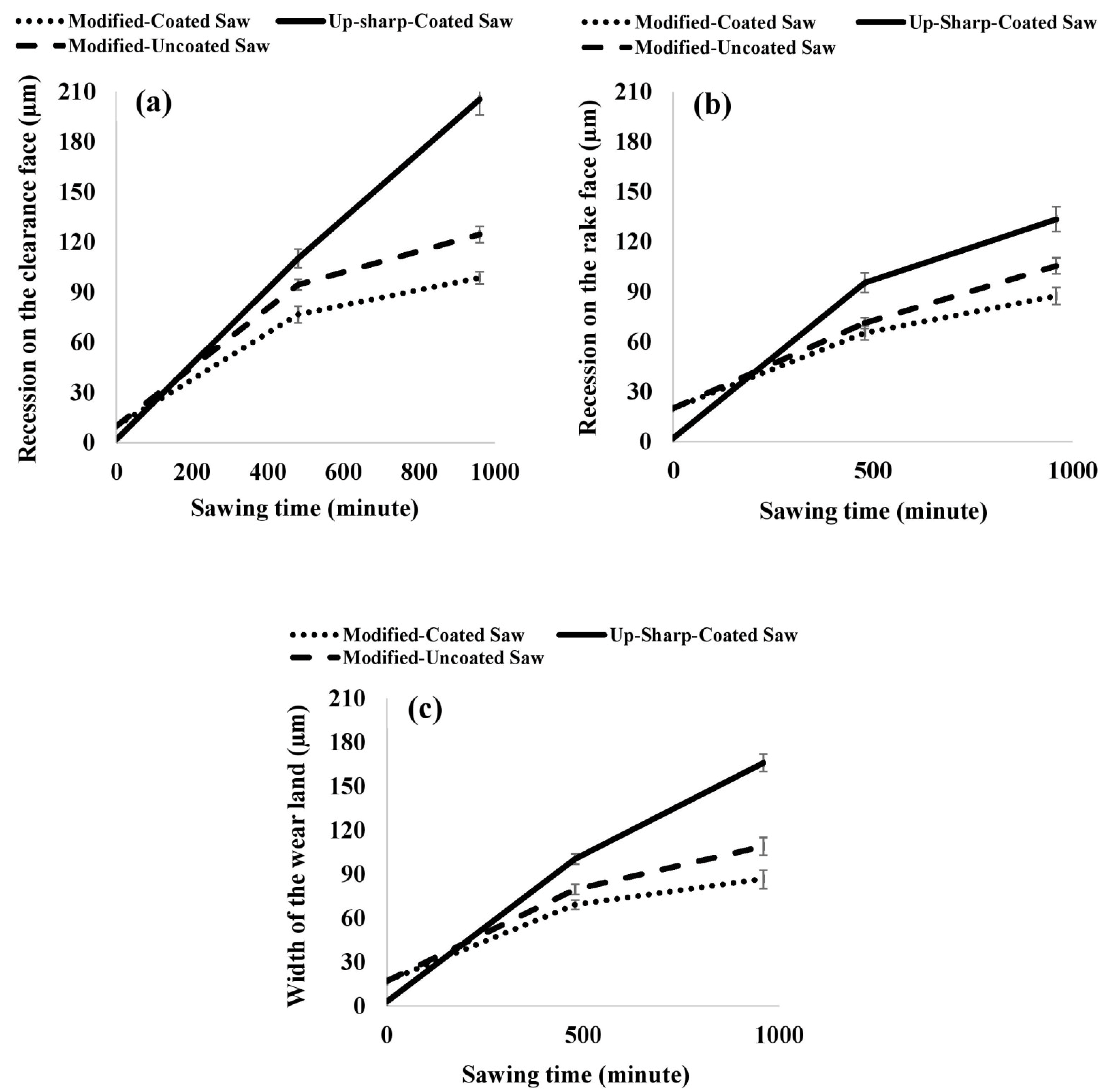
3.4. Results of Industrial Tests
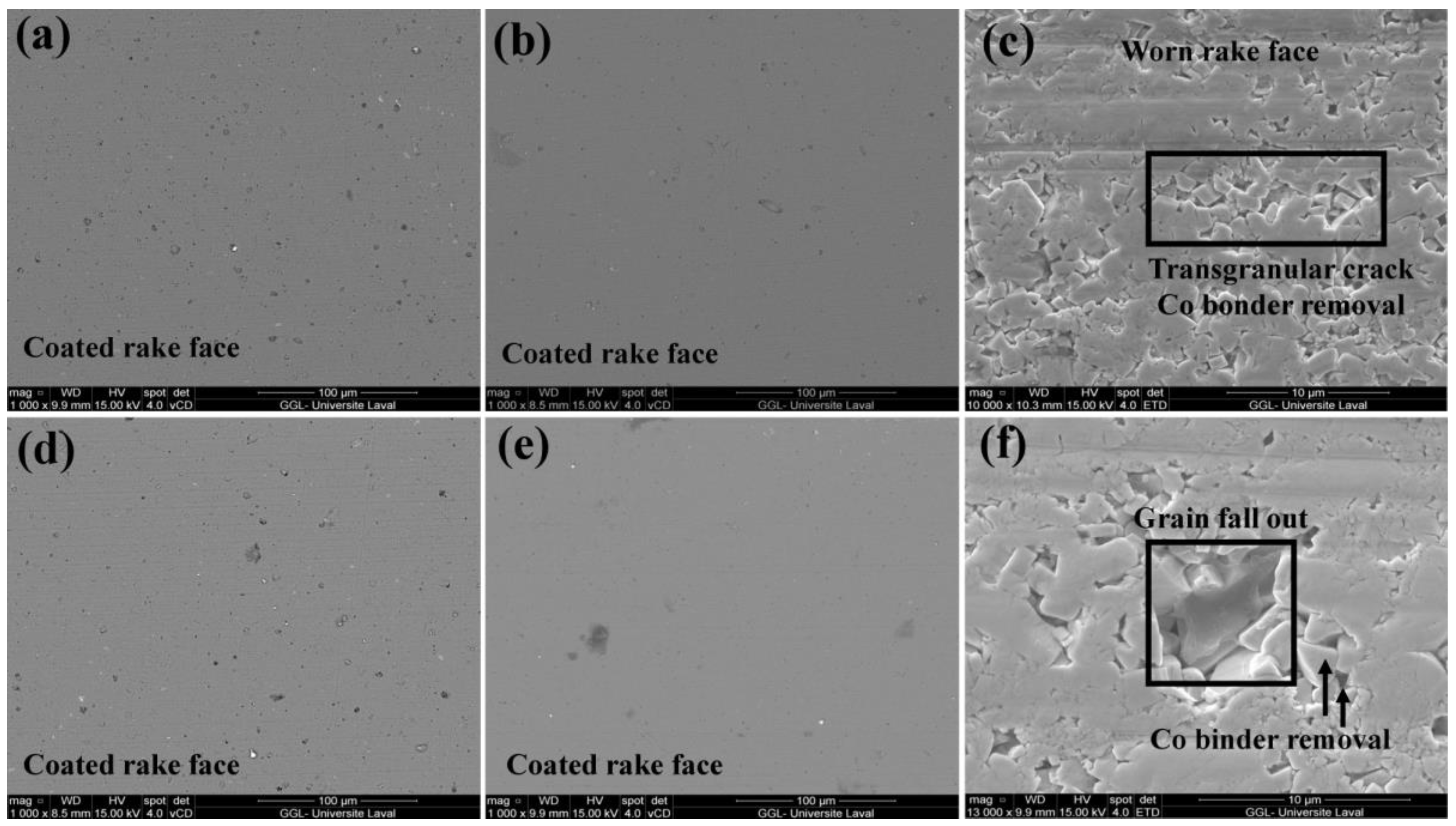
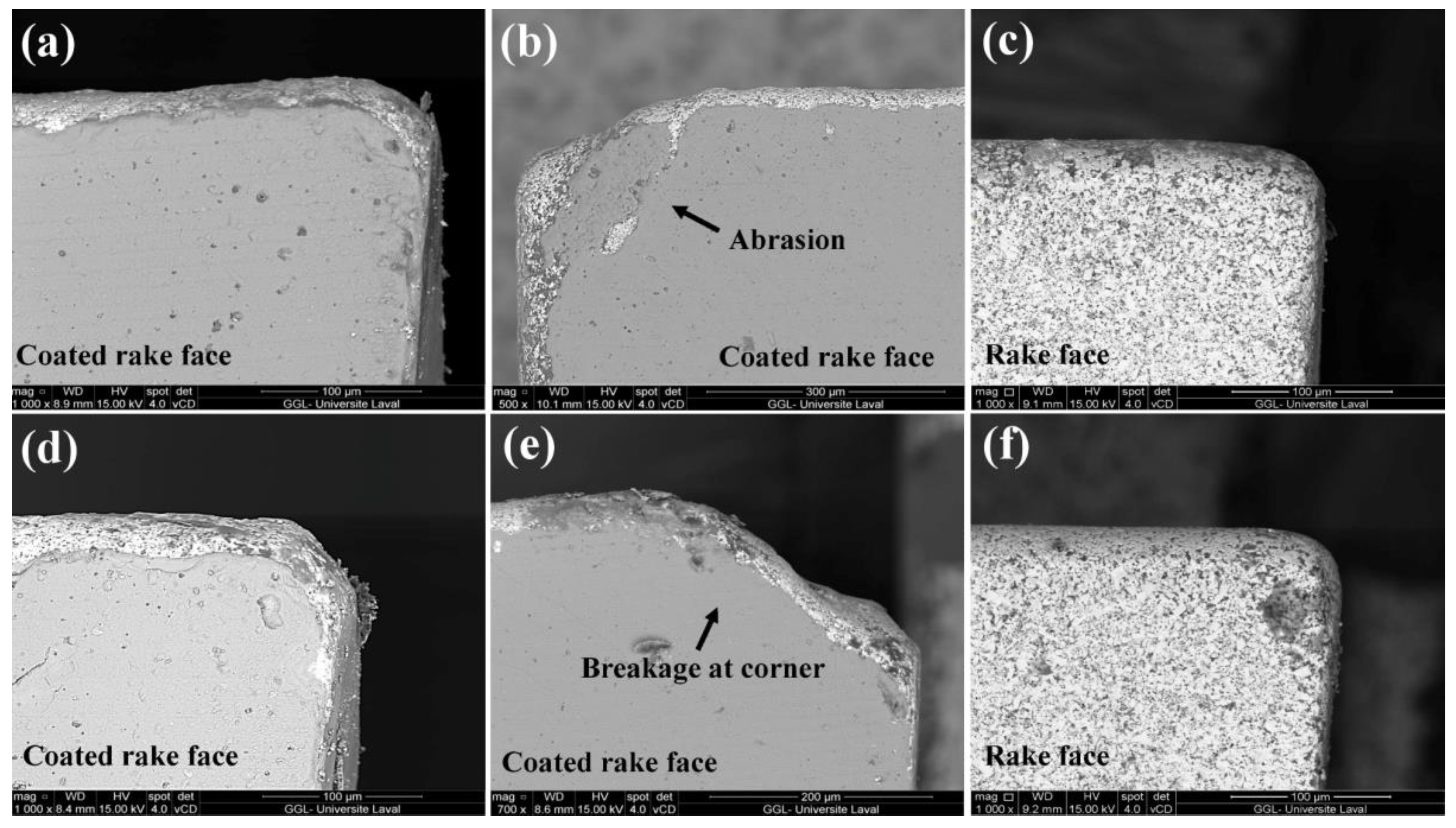
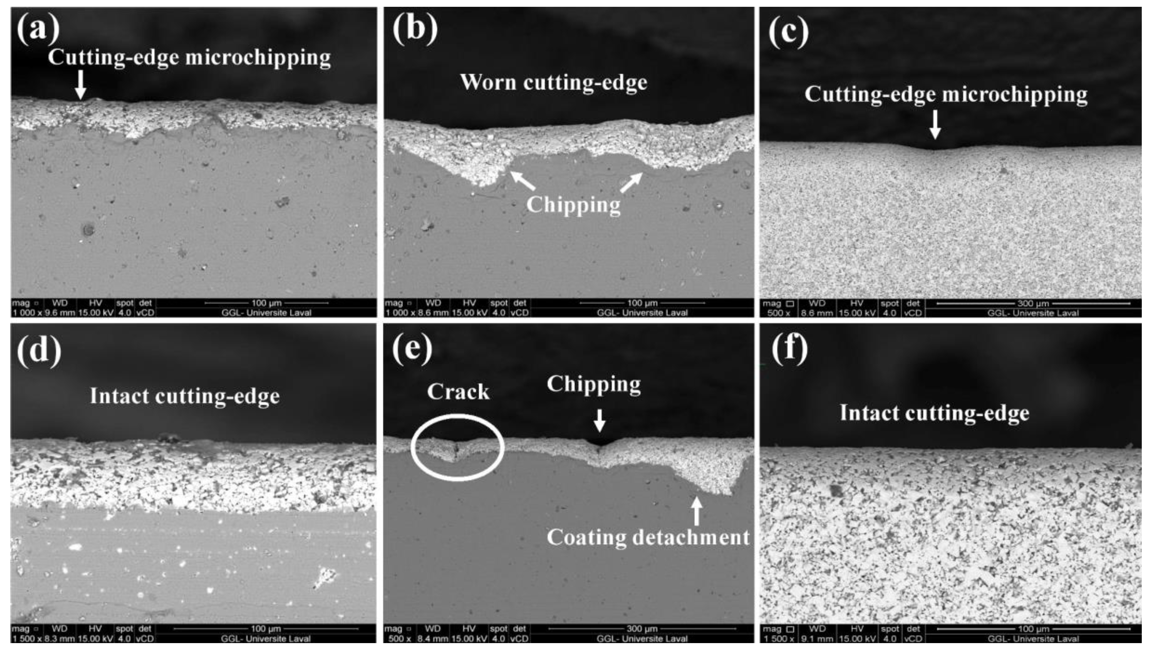
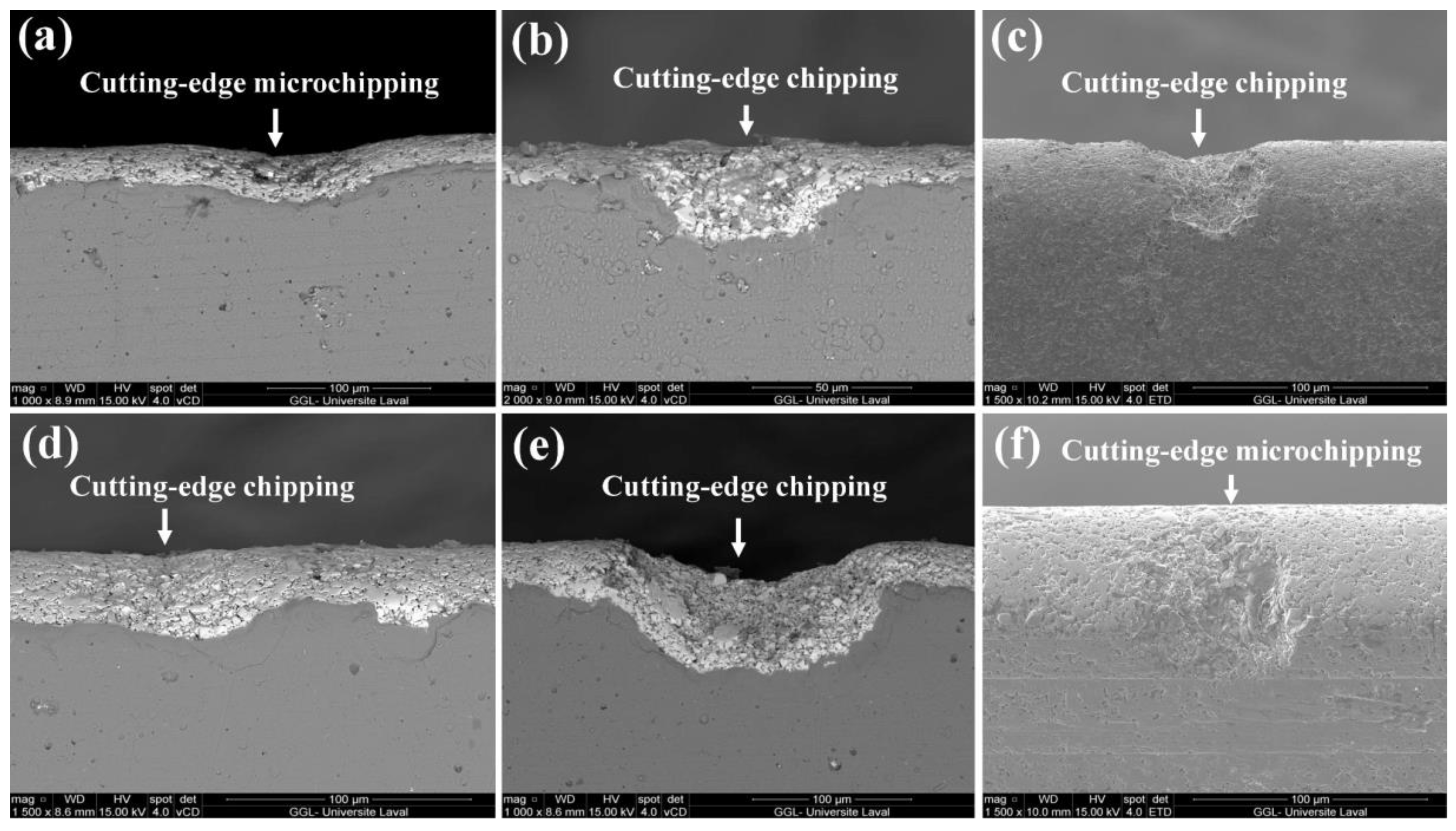
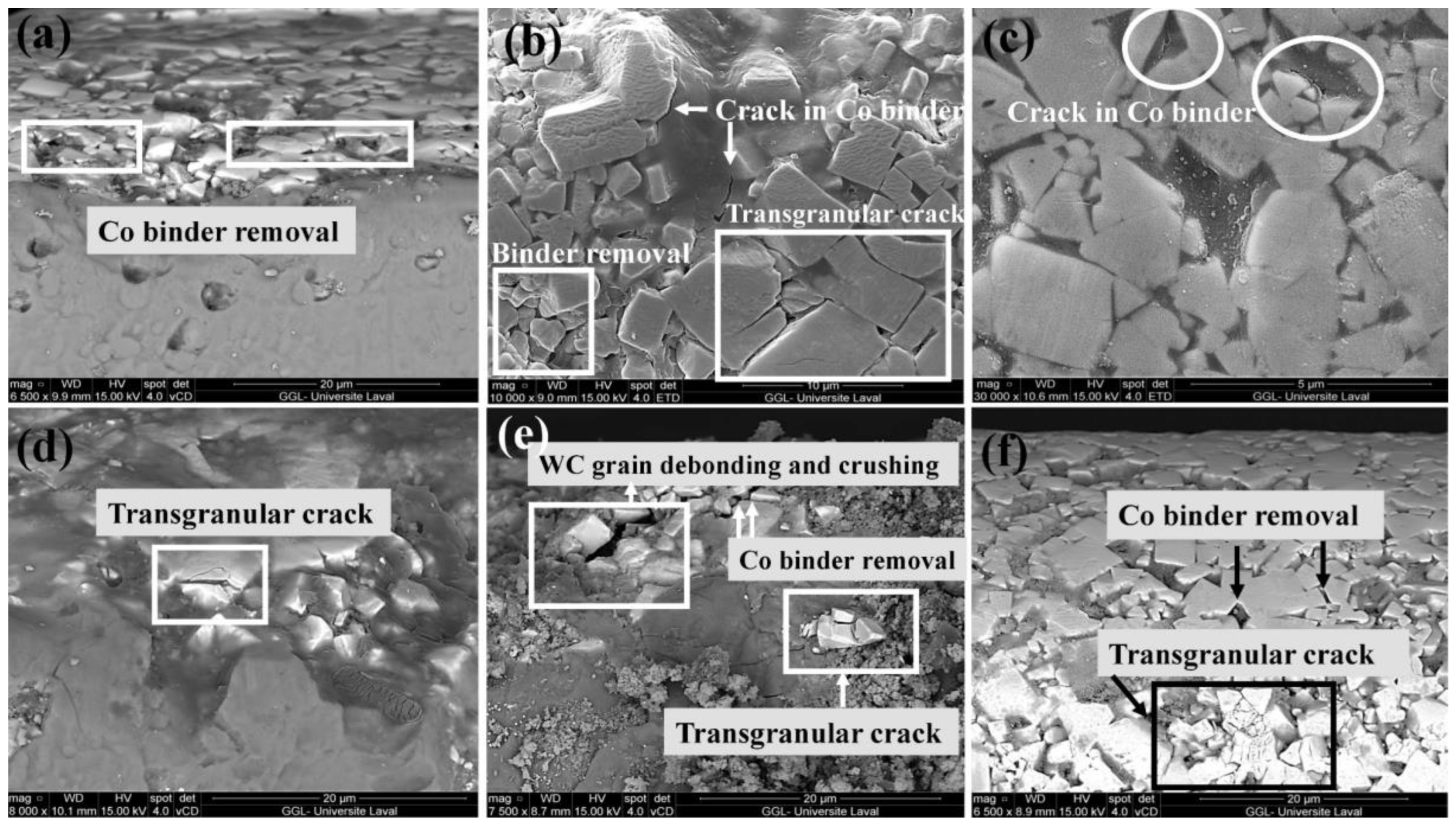
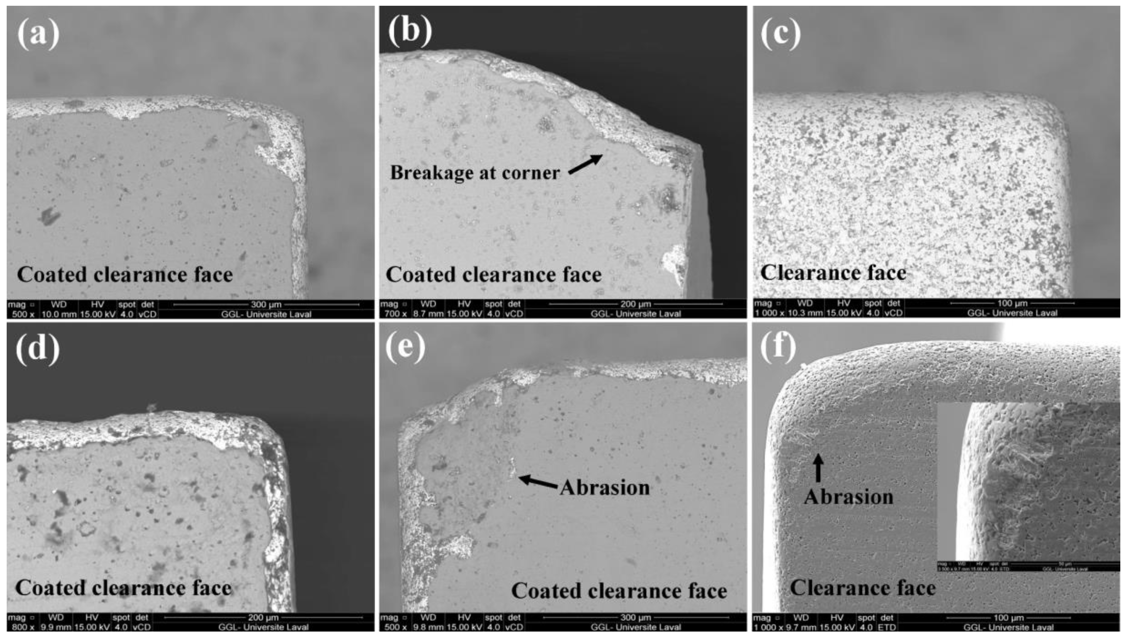
Wear Characterization of Tips
4. Conclusions
Author Contributions
Funding
Institutional Review Board Statement
Informed Consent Statement
Data Availability Statement
Acknowledgments
Conflicts of Interest
References
- Etele, C.; Magoss, E. Mechanics of Wood Machining, 2nd ed.; Springer: Sopron, Hungary, 2013. [Google Scholar]
- Geetha, R.; Jegatheswaran, R. A Review of Cemented Tungsten Carbide Tool Wear during Wood Cutting Processes. J. Appl. Sci. 2010, 10, 2799–2804. [Google Scholar]
- Nasir, V.; Cool, J. A Review on Wood Machining: Characterization, Optimization, and Monitoring of the Sawing Process. Wood Mater. Sci. Eng. 2020, 15, 1–16. [Google Scholar] [CrossRef]
- Nasr, M.N.A.; Ng, E.G.; Elbestawi, M.A. Modelling the Effects of Tool-Edge Radius on Residual Stresses When Orthogonal Cutting AISI 316L. Int. J. Mach. Tools Manuf. 2007, 47, 401–411. [Google Scholar] [CrossRef]
- Endres, W.J.; Kountanya, R.K. The Effects of Corner Radius and Edge Radius on Tool Flank Wear. J. Manuf. Process 2002, 4, 89–96. [Google Scholar] [CrossRef]
- Zhuang, K.; Fu, C.; Weng, J.; Hu, C. Cutting Edge Microgeometries in Metal Cutting: A Review. Int. J. Adv. Manuf. Technol. 2021, 116, 2045–2092. [Google Scholar] [CrossRef]
- Ventura, C.E.H.; Chaves, H.S.; Campos Rubio, J.C.; Abrão, A.M.; Denkena, B.; Breidenstein, B. The Influence of The Cutting Tool Microgeometry on the Machinability of Hardened AISI 4140 steel. Int. J. Adv. Manuf. Technol. 2017, 90, 2557–2565. [Google Scholar] [CrossRef]
- Wang, W.; Saifullah, M.K.; Aßmuth, R.; Biermann, D.; Arif, A.F.M.; Veldhuis, S.C. Effect of Edge Preparation Technologies on Cutting Edge Properties and Tool Performance. Int. J. Adv. Manuf. Technol. 2020, 106, 1823–1838. [Google Scholar] [CrossRef]
- Kazlauskas, D.; Jankauskas, V.; Kreivaitis, R.; Tučkutė, S. Wear Behaviour of PVD Coating Strengthened WC-Co Cutters During Milling of Oak-Wood. Wear 2022, 498, 204336. [Google Scholar] [CrossRef]
- Warcholinski, B.; Gilewicz, A. Multilayer Coatings on Tools for Woodworking. Wear 2011, 271, 2812–2820. [Google Scholar] [CrossRef]
- Labidi, C.; Collet, R.; Nouveau, C.; Beer, P.; Nicosia, S.; Djouadi, M.A. Surface Treatments of Tools Used in Industrial Wood Machining. Surf. Coat. Technol. 2005, 200, 118–122. [Google Scholar] [CrossRef]
- Minami, T.; Nishio, S. Effect of Cutting Tools with Advanced PVD Coating on Reduction of Power Consumption. In Proceedings of the 20th International Wood Machining Seminar, Skellefteå, Anders, Sweden, 7–10 June 2011. [Google Scholar]
- Miletić, A.; Panjan, P.; Škorić, B.; Čekada, M.; Dražič, G.; Kovač, J. Microstructure and Mechanical Properties of Nanostructured Ti-Al-Si-N Coatings Deposited by Magnetron Sputtering. Surf. Coat. Technol. 2014, 241, 105–111. [Google Scholar] [CrossRef]
- Ducros, C.; Sanchette, F. Multilayered and Nanolayered Hard nitride Thin Films Deposited by Cathodic Arc Evaporation. Part 2: Mechanical Properties and Cutting Performances. Surf. Coat. Technol. 2006, 201, 1045–1052. [Google Scholar] [CrossRef]
- Pinheiro, D.; Vieira, M.T.; Djouadi, M.A. Advantages of Depositing Multilayer Coatings for Cutting Wood-Based Products. Surf. Coat. Technol. 2009, 203, 3197–3205. [Google Scholar]
- Kong, Y.; Tian, X.; Gong, C.; Chu, P.K. Enhancement of Toughness and Wear Resistance by CrN/CrCN Multilayered Coatings for Wood Processing. Surf. Coat. Technol. 2018, 344, 204–213. [Google Scholar] [CrossRef]
- Erdemir, A. A Crystal Chemical Approach to the Formulation of Self-Lubricating Nanocomposite Coatings. Surf. Coat. Technol. 2005, 200, 1792–1796. [Google Scholar] [CrossRef]
- Czarniak, P.; Szymanowski, K.; Kucharska, B.; Krawczyńska, A.; Sobiecki, J.R.; Kubacki, J.; Panjan, P. Modification of Tools for Wood Based Materials Machining with TiAlN/a-CN Coating. Mater. Sci. Eng. B Solid-State Mater. Adv. Technol. 2020, 257, 114540. [Google Scholar] [CrossRef]
- Wang, L.; Bai, L.; Lu, Z.; Zhang, G.; Wu, Z. Influence of Load on the Tribological Behavior of a-C films: Experiment and Calculation Coupling. Tribol. Lett. 2013, 52, 469–475. [Google Scholar] [CrossRef]
- Faga, M.G.; Settineri, L. Innovative Anti-Wear Coatings on Cutting Tools for Wood Machining. Surf. Coat. Technol. 2006, 201, 3002–3007. [Google Scholar] [CrossRef]
- Vidakis, N.; Antoniadis, A.; Bilalis, N. The VDI 3198 Indentation Test Evaluation of a Reliable Qualitative Control for Layered Compounds. J. Mater. Process. Technol. 2003, 143, 481–485. [Google Scholar] [CrossRef]
- ASTM G65-04; Standard Test Method for Measuring Abrasion Using the Dry Sand/Rubber Wheel. ASTM Standards: West Conshohocken, PA, USA, 2010; Volume 0302.
- Circular Saw Blade Edge Prep Machine. Available online: http://conicity.com/machines (accessed on 1 November 2018).
- Csanády, E.; Magoss, E. Vibration of the tools and workpieces. In Mechanics of Wood Machining, 2nd ed.; Springer: Sopron, Hungary, 2013; pp. 89–126. [Google Scholar]
- Darmawan, W.; Rahayu, I.; Nandika, D.; Marchal, R. The Importance of Extractives and Abrasives in Wood Materials on the Wearing of Cutting Tools. BioResources 2012, 7, 4715–4729. [Google Scholar] [CrossRef] [Green Version]
- Panjan, P.; Čekada, M.; Panjan, M.; Kek-Merl, D. Growth Defects in PVD Hard Coatings. Vaccum 2009, 84, 209–214. [Google Scholar] [CrossRef]
- Panjan, P.; Drnovšek, A.; Gselman, P.; Čekada, M.; Panjan, M. Review of Growth Defects in Thin Films Prepared by PVD Techniques. Coatings 2020, 10, 447. [Google Scholar] [CrossRef]
- Cedeño-Venté, M.L.; Espinosa-Arbeláez, D.G.; Manríquez-Rocha, J.; Mondragón-Rodríguez, G.C.; Gómez-Ovalle, A.E.; González-Hernández, J.; Alvarado-Orozco, J.M. Effect of Graded Bias Voltage on the Microstructure of Arc-PVD CrN Films and its Response in Electrochemical & Mechanical Behavior. arXiv 2018, arXiv:1810.07293. [Google Scholar]
- Ahn, S.H.; Lee, J.H.; Kim, J.G.; Han, J.G. Localized Corrosion Mechanisms of the Multilayered Coatings Related to Growth Defects. Surf. Coat. Technol. 2004, 177, 638–644. [Google Scholar] [CrossRef]
- Image J Analysis Software. Available online: https://imagej.nih.gov/ij/download.html (accessed on 1 March 2019).
- Lee, W.Y.; Jang, Y.J.; Tokoroyama, T.; Murashima, M.; Umehara, N. Effect of Defects on Wear Behavior in ta-C Coating Prepared by Filtered Cathodic Vacuum Arc Deposition. Diam. Relat. Mater. 2020, 105, 107789. [Google Scholar] [CrossRef]
- Claver, A.; Jiménez-Piqué, E.; Palacio, J.F.; Almandoz, E.; Fernández de Ara, J.; Fernández, I.; Santiago, J.A.; Barba, E.; García, J.A. Comparative Study of Tribomechanical Properties of HiPIMS with Positive Pulses DLC Coatings on Different Tools Steels. Coatings 2020, 11, 28. [Google Scholar] [CrossRef]
- Gilewicz, A.; Warcholinski, B. Tribological Properties of CrCN/CrN Multilayer Coatings. Tribol. Int. 2014, 80, 34–40. [Google Scholar] [CrossRef]
- Dalibón, E.L.; Pecina, J.N.; Moscatelli, M.N.; Ramírez Ramos, M.A.; Trava-Airoldi, V.J.; Brühl, S.P. Mechanical and Corrosion Behaviour of DLC and TiN Coatings Deposited on Martensitic Stainless Steel. J. Bio- Tribo-Corros. 2019, 5, 1–9. [Google Scholar] [CrossRef]
- Warcholinski, B.; Gilewicz, A. The Properties of Multilayer CrCN/CrN Coatings Dependent on Their Architecture. Plasma Process Polym. 2011, 8, 333–339. [Google Scholar] [CrossRef]
- Gao, B.; Du, X.; Li, Y.; Wei, S.; Zhu, X.; Song, Z. Effect of Deposition Temperature on Hydrophobic CrN/AlTiN Nanolaminate Composites Deposited by Multi-Arc-Ion Plating. J. Alloys Compd. 2019, 797, 1–9. [Google Scholar] [CrossRef]
- Luo, Q.; Zhu, J. Wear Property and Wear Mechanisms of High-Manganese Austenitic Hadfield Steel in Dry Reciprocal Sliding. Lubricants 2022, 10, 37. [Google Scholar] [CrossRef]
- Abedi, M.; Abdollah-zadeh, A.; Bestetti, M.; Vicenzo, A.; Serafini, A.; Movassagh-Alanagh, F. The Effects of Phase Transformation on the Structure and Mechanical Properties of TiSiCN Nanocomposite Coatings Deposited by PECVD method. Appl. Surf. Sci. 2018, 444, 377–386. [Google Scholar] [CrossRef]
- Luo, Q. Temperature Dependent Friction and Wear of Magnetron Sputtered Coating TiAlN/VN. Wear 2011, 271, 2058–2066. [Google Scholar] [CrossRef]
- Wang, R.; Mei, H.J.; Li, R.S.; Zhang, Q.; Zhang, T.F.; Wang, Q.M. Friction and Wear Behavior of AlTiN-Coated Carbide Balls Against SKD11 Hardened Steel at Elevated Temperatures. Acta Metall. Sin. 2018, 31, 1073–1083. [Google Scholar] [CrossRef] [Green Version]
- Wang, H.; Ou, Y.; Zhang, X.; Liao, B.; Ou, X.; Luo, J.; Pang, P.; Chen, L.; Hua, Q.; Bao, M. Tribocorrosion Behaviors of TiSiCN Nanocomposite Coatings Deposited by High Power Impulse Magnetron Sputtering. Mater. Res. Express 2020, 7, 076407. [Google Scholar] [CrossRef]
- Zhou, B.; Jin, W.; Liu, Z.; Ma, Y.; Gao, J.; Wang, Y.; Yu, S. Effect of N Content on the Microstructure and Tribological Properties of TiSiCN Composite Coatings. J. Vac. Sci. Technol. A. 2022, 40, 043407. [Google Scholar] [CrossRef]
- Ndlovu, S. The Wear Properties of Tungsten Carbide-Cobalt Hardmetals from the Nanoscale up to the Macroscopic Scale. Ph.D. Thesis, Friedrich-Alexander-Universität Erlangen-Nürnberg (FAU), Erlangen, Germany, 2009. [Google Scholar]
- Hsieh, J.H.; Tan, A.L.K.; Zeng, X.T. Oxidation and Wear Behaviors of Ti-Based Thin Films. Surf. Coat. Technol. 2006, 201, 4094–4098. [Google Scholar] [CrossRef]
- Mo, J.L.; Zhu, M.H.; Lei, B.; Leng, Y.X.; Huang, N. Comparison of Tribological Behaviours of AlCrN and TiAlN Coatings-Deposited by Physical Vapor Deposition. Wear 2007, 263, 1423–1429. [Google Scholar] [CrossRef]
- Tlili, B.; Nouveau, C.; Guillemot, G.; Besnard, A.; Barkaoui, A. Investigation of the Effect of Residual Stress Gradient on the Wear Behavior of PVD Thin Films. J. Mater. Eng. Perform. 2018, 27, 457–470. [Google Scholar] [CrossRef] [Green Version]
- Lukaszkowicz, K.; Sondor, J.; Paradecka, A.; Pawlyta, M.; Chmiela, B.; Pancielejko, M.; Szczucka-Lasota, B.; Węgrzyn, T.; Tański, T. Structure and Tribological Properties of alcrn + crcn Coating. Coatings 2020, 10, 1084. [Google Scholar] [CrossRef]
- Sima, M.; Ulutan, D.; Özel, T. Effects of tool micro-geometry and coatings in turning of Ti-6Al-4V titanium alloy. In Proceedings of the NAMRI/SME 39, Corvallis, OR, USA, 13–17 June 2011. [Google Scholar]
- Djouadi, M.A.; Beer, P.; Marchal, R.; Sokolowska, A.; Lambertin, M.; Precht, W.; Nouveau, C. Antiabrasive Coatings: Application for Wood Processing. Surf. Coat. Technol. 1999, 116, 508–516. [Google Scholar] [CrossRef]
- Cristóvão, L.; Ekevad, M.; Grönlund, A. Industrial Sawing of Pinus sylvestris L.: Power Consumption. BioResources 2013, 8, 6044–6053. [Google Scholar]
- Guo, X.; Ekevad, M.; Grönlund, A.; Marklund, B.; Cao, P. Tool Wear and Machined Surface Roughness During Wood Flour/Polyethylene Composite Peripheral Upmilling Using Cemented Tungsten Carbide Tools. BioResources 2014, 9, 3779–3791. [Google Scholar] [CrossRef]
- Ardalan, E. The Effect of Tool Edge Radius on Cutting Conditions Based on Updated Lagrangian Formulation in Finite Element Method. Ph.D. Thesis, McMaster University, Hamilton, ON, Canada, 2018. [Google Scholar]
- Rodríguez, C.J.C. Cutting Edge Preparation of Precision Cutting Tools by Applying Micro-Abrasive Jet Machining and Brushing. Ph.D. Thesis, Kassel University, Kassel, Germany, 2009. [Google Scholar]
- Sacks, N. The Wear and Corrosive-Wear Response of Tungsten Carbide-Cobalt Hardmetals Under Woodcutting and Three Body Abrasion Conditions. Ph.D. Thesis, Friedrich-Alexander-Universität Erlangen-Nürnberg (FAU), Erlangen, Germany, 2003. [Google Scholar]
- Hernández, R.E.; de Moura, L.F. Effects of Knife Jointing and Wear on the Planed Surface Quality of Northern Red Oak Wood. Wood Fiber Sci. 2002, 34, 540–552. [Google Scholar]
- Wu, X.; Li, L.; He, N.; Yao, C.; Zhao, M. Influence of the Cutting Edge Radius and the Material Grain Size on the Cutting Force in Micro Cutting. Precis. Eng. 2016, 45, 359–364. [Google Scholar] [CrossRef]
- Karpat, Y.; Özel, T. Mechanics of High Speed Cutting with Curvilinear Edge Tools. Int. J. Mach. Tools Manuf. 2008, 48, 195–208. [Google Scholar] [CrossRef]
- Padmakumar, M. Effect of Cutting Edge Form Factor (K-factor) on the Performance of a Face Milling Tool. CIRP J. Manuf. Sci. Technol. 2020, 31, 305–313. [Google Scholar]
- Benlatreche, Y. Contribution to the Improvement of the Lifetime of Carbide Tools for the Machining of MDF (Medium Density Fiberboard) by Application of Ternary Deposits (CrAlN, CrVN) and Modification of the Cutting Edge. Ph.D. Thesis, Arts et Métiers ParisTech, Paris, France, 2011. [Google Scholar]


| Coating | Target | Temperature Deposition | Bilayer Period |
|---|---|---|---|
| CrN/AlTiN | Cr and TiSi80/20 | 250 °C | 1:1 |
| CrN/CrCN | Cr | 250 °C | 1:1 |
| CrN/CrCN/DLC | Cr | 250 °C | 1:1 |
| CrCN/TiSiCN | Cr and AlTi67/33 | 250 °C | 1:1 |
| Parameters | Value |
|---|---|
| Saw body material | AISI 8670 |
| Tip material | 88% WC and 12% Co |
| Number of tips | 42 |
| Saw diameter (mm) | 610 |
| Saw thickness (mm) | 2.79 |
| kerf width (mm) | 3.91 |
| Wedge angle | 56.3° |
| Rake angle | 24.7° |
| Top clearance angle | 9° |
| Radial clearance angle (left and right) | 1° |
| Left side clearance (mm) | 0.56 |
| Right side clearance (mm) | 0.58 |
| Supplier of the saws: Haskin Industrial Co., North Bay, ON, Canada. | |
| Saw Identification | Coating | Edge Modification |
|---|---|---|
| #1, #2 | Yes | Yes |
| #3, #4 | Yes | No |
| #5, #6 | No | Yes |
| Coating | Atomic % | Thickness (µm) | Hardness (GPa) | |||||
|---|---|---|---|---|---|---|---|---|
| Cr | N | C | Al | Ti | Si | |||
| CrN/AlTiN | 7 | 69 | - | 17 | 7 | - | 1.9 | 34 |
| CrN/CrCN | 19 | 57 | 24 | - | - | - | 1.5 | 24 |
| CrN/CrCN/DLC | 11 | 32 | 57 | - | - | - | 2.2 | 22 |
| CrCN/TiSiCN | 5 | 59 | 25 | - | 9 | 2 | 1.8 | 31 |
| Element | % Mass | % Atomic |
|---|---|---|
| C | 7.83 | 13.34 |
| N | 12.79 | 18.70 |
| O | 41.11 | 52.60 |
| Al | 1.07 | 0.81 |
| Si | 0.95 | 0.69 |
| W | 2.93 | 0.33 |
| Ti | 12.50 | 5.34 |
| Cr | 20.81 | 8.19 |
| Test | CrN/CrCN/DLC | CrN/AlTiN | CrN/CrCN | CrCN/TiSiCN | |
|---|---|---|---|---|---|
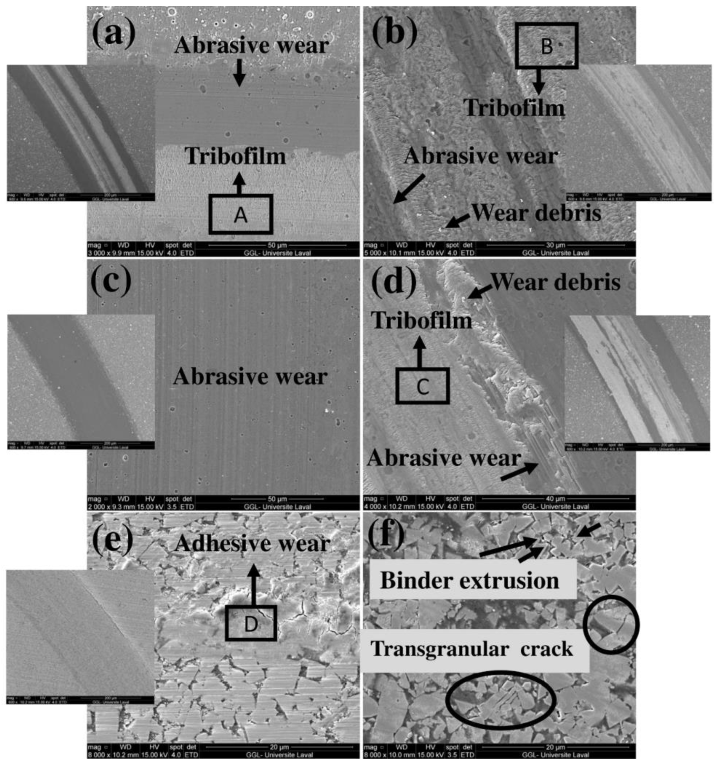
| Sliding wear test | Abrasive wear | × | × | × | × |
| Adhesive wear | × | × | × | × | |
| Cracking | × | × | |||
| Delamination | × | × | |||
| DSRW test | Abrasive wear | × | × | ||
| Cracking | × | ||||
| Delamination | × | × | |||
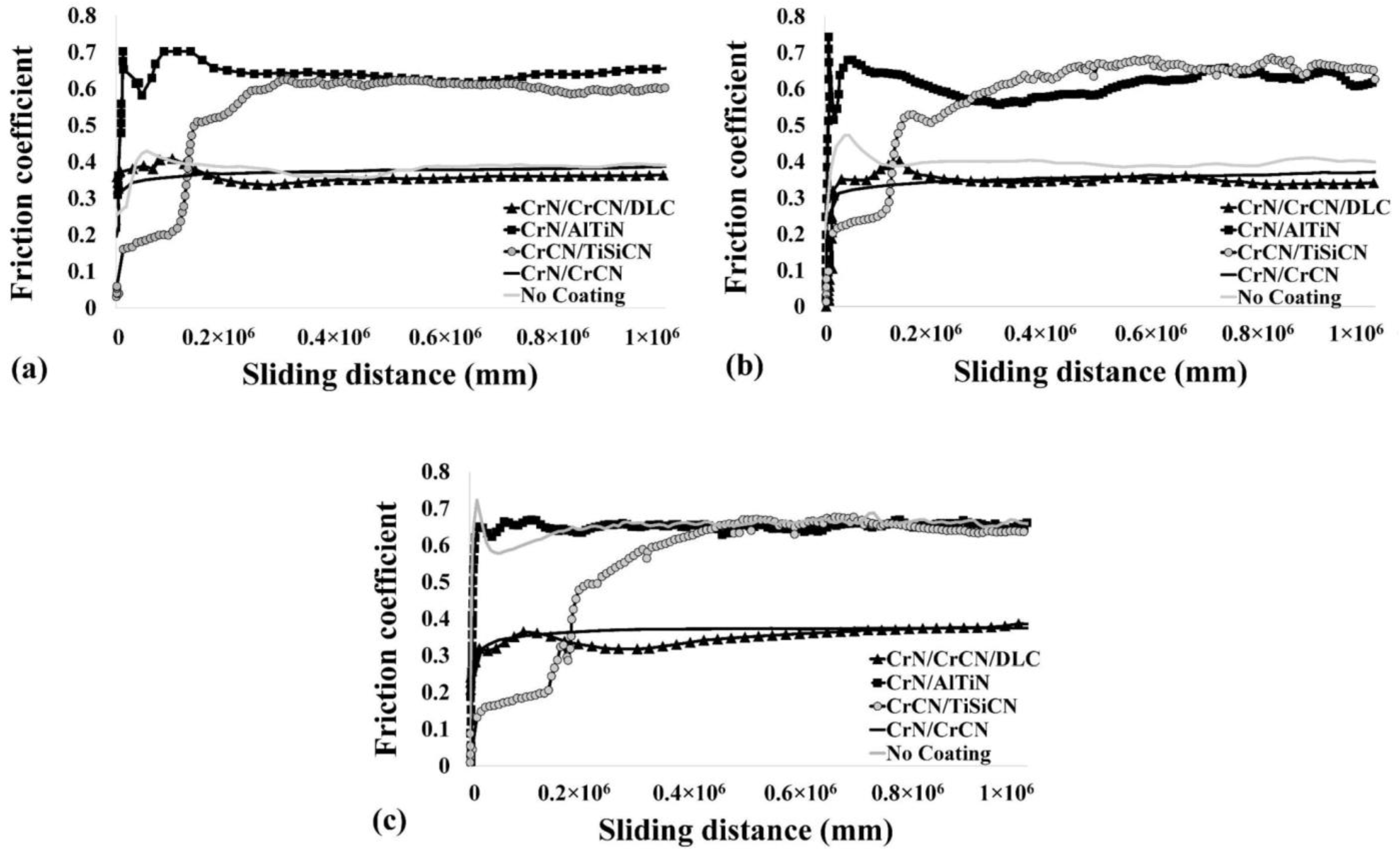
| Friction coefficient at 250 mm/s | 0.30 | 0.65 | 0.31 | 0.56 | |
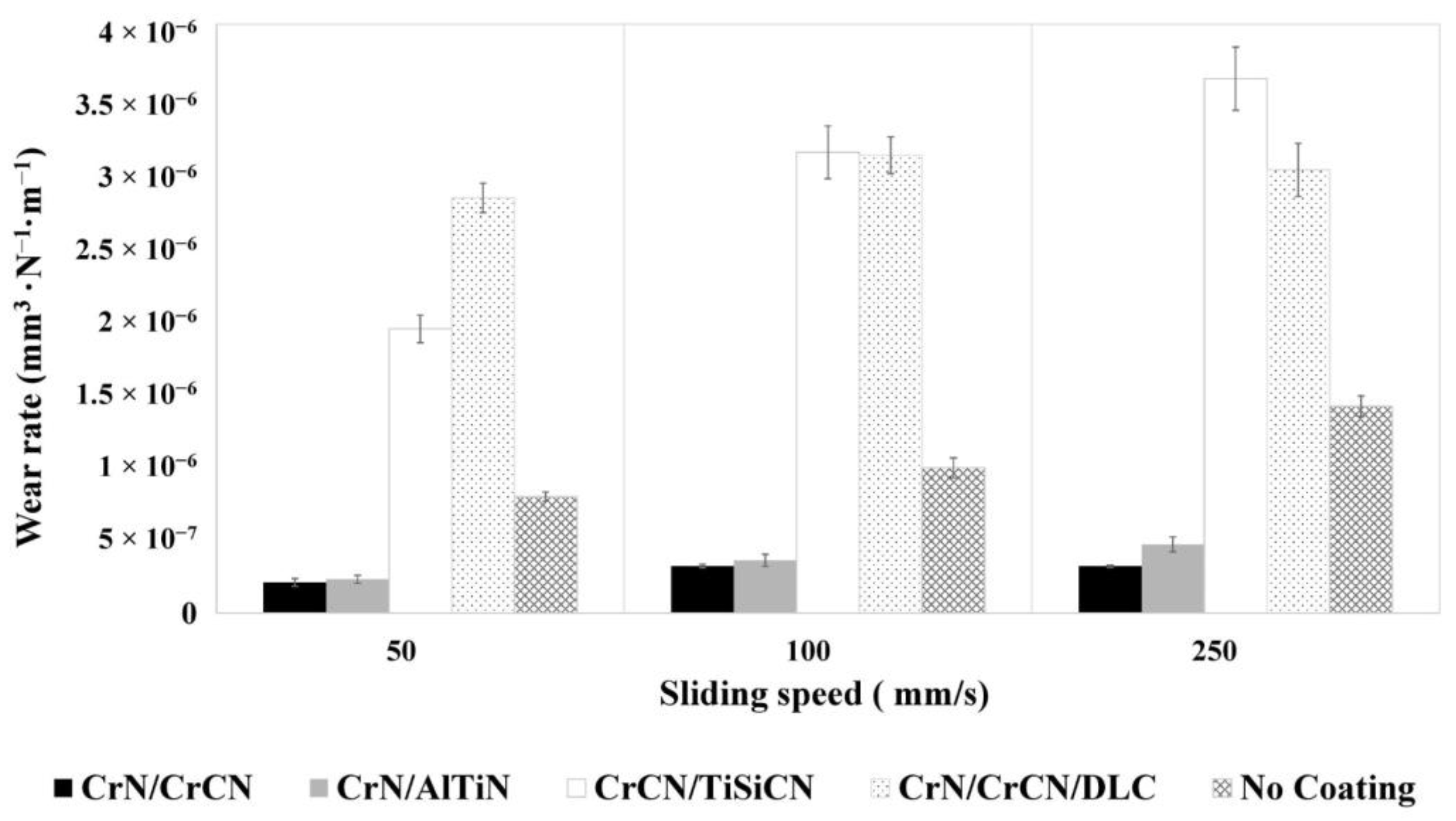
| Wear rate at 250 mm/s (mm3 N−1·m−1) | 3.01 × 10⁻⁶ | 4.67 × 10⁻⁷ | 3.18 × 10⁻⁷ | 3.63 × 10⁻⁶ | |
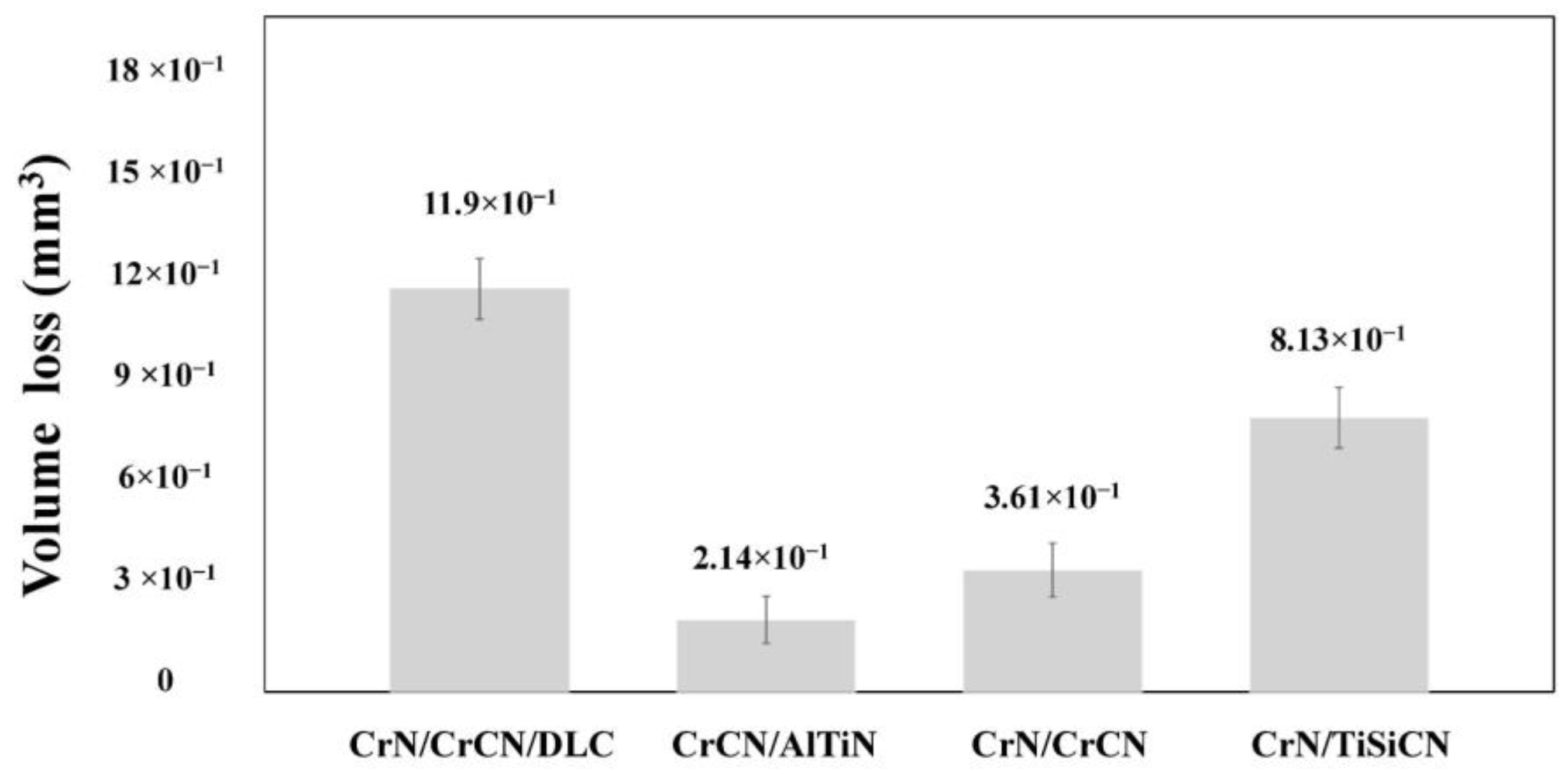
| Volume loss after DSRW test (mm3) | 11.9 × 10⁻¹ | 2.14 × 10⁻¹ | 3.61 × 10⁻¹ | 8.13 × 10⁻¹ | |
| Saw Identification | Modified Saw | Up-Sharp Saw |
|---|---|---|
| Recession on clearance face (µm) | 10 | 3 |
| Recession on rake face (µm) | 20 | 3 |
| Width of the wear land (µm) | 17 | 2 |
| Saw Identification | First Phase of the Test (between 0 min and 480 min of Sawing) | Second Phase of the (between 480 min and 960 min of Sawing) | ||||
|---|---|---|---|---|---|---|
| Rate of Wear on the Clearance Face (µm/h) | Rate of Wear on the Rake Face (µm/h) | Rate of Increase of Wear Land (µm/h) | Rate of Wear on the Clearance Face (µm/h) | Rate of Wear on the Rake Face (µm/h) | Rate of Increase of Wear Land (µm/h) | |
| #2 | 11.1 | 7.6 | 8.7 | 3.7 | 3.7 | 2.9 |
| #4 | 18.0 | 15.6 | 16.2 | 15.9 | 6.3 | 10.9 |
| #6 | 14.1 | 8.5 | 10.4 | 5.0 | 5.7 | 4.9 |
| Saw Identification | After 480 min of Utilization (between 0 min and 480 min of Sawing) | After 480 min of Utilization (between 480 min and 960 min of Sawing) | ||||
|---|---|---|---|---|---|---|
| Clearance Face | Rake Face | Wear Land | Clearance Face | Rake Face | Wear Land | |
| Decrease in wear rate of saw #2 compared to saw #4 | 38% | 51% | 46% | 77% | 41% | 73% |
| Decrease in wear rate of saw #2 compared to saw #6 | 21% | 11% | 16% | 26% | 53% | 41% |
Publisher’s Note: MDPI stays neutral with regard to jurisdictional claims in published maps and institutional affiliations. |
© 2022 by the authors. Licensee MDPI, Basel, Switzerland. This article is an open access article distributed under the terms and conditions of the Creative Commons Attribution (CC BY) license (https://creativecommons.org/licenses/by/4.0/).
Share and Cite
Torkghashghaei, M.; Shaffer, W.; Ugulino, B.; Georges, R.; Hernández, R.E.; Blais, C. Improvement of the Wear Resistance of Circular Saws Used in the First Transformation of Wood through the Utilization of Variable Engineered Micro-Geometry Performed on PVD-Coated WC-Co Tips. Appl. Sci. 2022, 12, 12213. https://doi.org/10.3390/app122312213
Torkghashghaei M, Shaffer W, Ugulino B, Georges R, Hernández RE, Blais C. Improvement of the Wear Resistance of Circular Saws Used in the First Transformation of Wood through the Utilization of Variable Engineered Micro-Geometry Performed on PVD-Coated WC-Co Tips. Applied Sciences. 2022; 12(23):12213. https://doi.org/10.3390/app122312213
Chicago/Turabian StyleTorkghashghaei, Maryam, William Shaffer, Bruna Ugulino, Rémi Georges, Roger E. Hernández, and Carl Blais. 2022. "Improvement of the Wear Resistance of Circular Saws Used in the First Transformation of Wood through the Utilization of Variable Engineered Micro-Geometry Performed on PVD-Coated WC-Co Tips" Applied Sciences 12, no. 23: 12213. https://doi.org/10.3390/app122312213