Article

Influence of Warm Isostatic Press Process on Mechanical Properties of a Part Fabricated by Metal Material Extrusion Process

1
School of Mechanical Engineering, Korea University, 145 Anam-ro, Seongbuk-gu, Seoul 02841, Republic of Korea
2
Additive Manufacturing Innovation Agency, Korea Institute of Industrial Technology (KITECH), 113-58 Seohaean-ro, Siheung-si 15014, Republic of Korea
3
Functional Materials and Components R&D Group, Korea Institute of Industrial Technology, Gangneung 25440, Republic of Korea
4
School of Energy Engineering, Konkuk University, 120 Neungdong-ro, Gwangjin-gu, Seoul 05029, Republic of Korea
5
School of Mechanical and Robotics Engineering, Tongmyoung University, 428 Sinseon-ro, Nam-gu, Busan 48520, Republic of Korea
*
Authors to whom correspondence should be addressed.
Appl. Sci. 2022, 12(23), 12240; https://doi.org/10.3390/app122312240
Submission received: 19 October 2022 / Revised: 24 November 2022 / Accepted: 25 November 2022 / Published: 29 November 2022

Abstract

:
Material extrusion (ME) using a filament including metal powders has recently attracted considerable attention because it allows the production of metal parts at low cost. However, like other additive manufacturing processes, metal ME suffers from the problem of internal pores. In this study, warm isostatic pressure (WIP)—a post-process used to downsize or remove the pores in polymer ME—was employed in metal ME to improve the mechanical properties of the finished part. It was confirmed experimentally that the tensile strength and the strain at the ultimate tensile strength were increased by WIP. However, from hardness tests, two different results were obtained. On a microscopic scale, there was no change in hardness because the temperature of the WIP process was not high enough to change the microstructure, while on a macroscopic scale, the hardness changed owing to the collapse of the pores within the material under the indenter load. In specimens with relatively large pores, the hardness sensitivity increases with a larger indenter. Finally, factors affecting the WIP process parameters in metal ME were discussed.

1. Introduction

Additive manufacturing (AM) technologies produce parts layer by layer [1,2]. This enables complex parts to be fabricated in a single process and endowed with multi-mechanical properties [3]. Therefore, AM has been widely adopted in the aerospace, defense, medical, automotive, and many other industries [4,5]. AM technologies can be classified in various ways [6]; in ASTM F2792-12, AM are divided into seven categories: material extrusion (ME), vat photopolymerization (VP), material jetting (MJ), binder jetting (BJ), powder-bed fusion (PBF), direct-energy deposition (DED), and lamination (SL) [7].
The first of these, ME, is based on the extrusion of melted polymer. In ME, various thermoplastics can be used, e.g., polylactic acid (PLA), acrylonitrile butadiene styrene (ABS), or polycarbonate (PC) [8,9,10]. Because of the simple mechanism involved, the cost of the necessary machinery (often available from open-source projects) is relatively low. In addition, ME is the only AM process with a deposition mechanism suitable for use in the space environment [11].
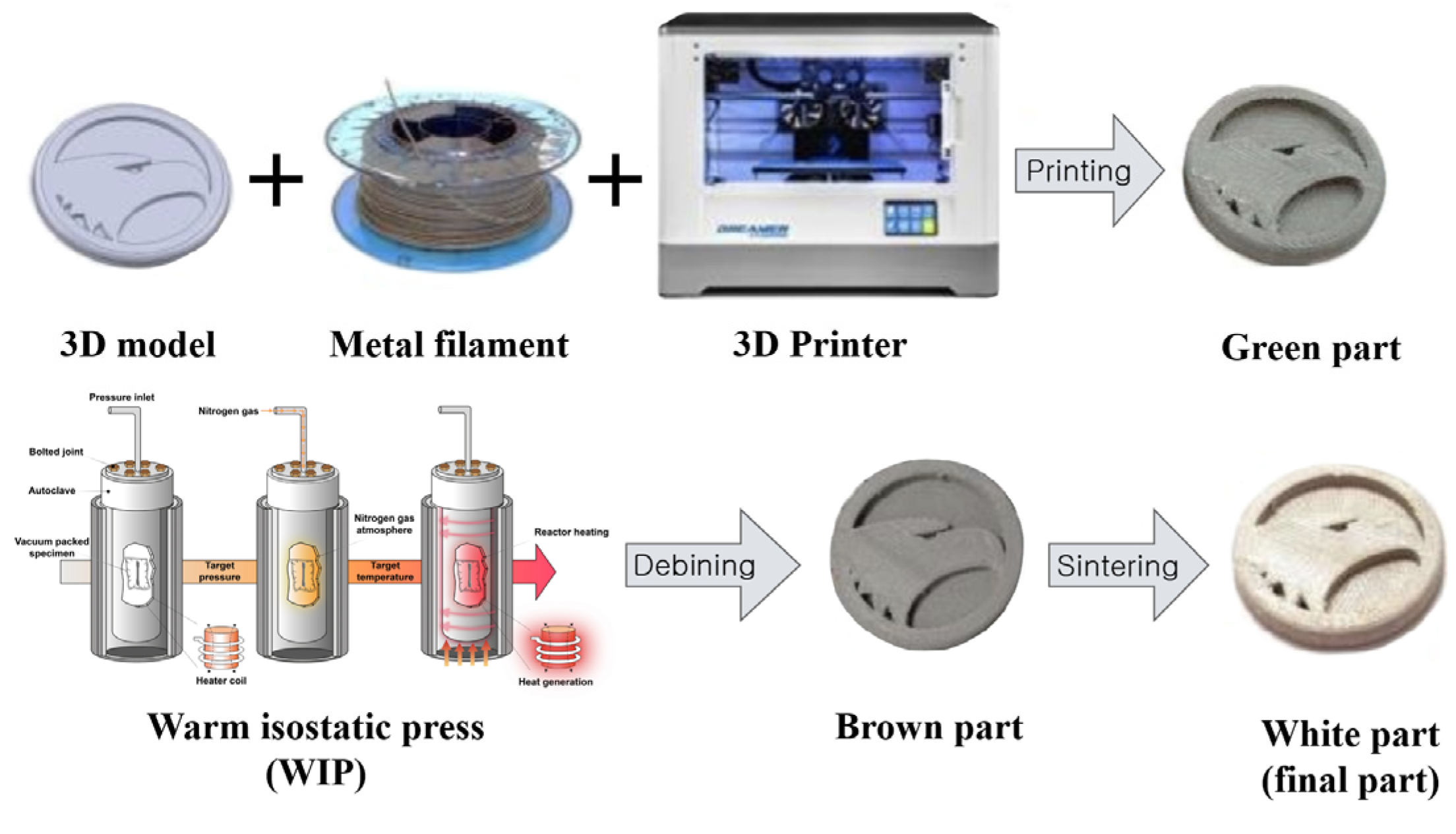
In the traditional ME process, a polymer filament is extruded from a pellet to fabricate the part. Recently, metal/ceramic filaments have been developed by adding the metal/ceramic powders into the polymer-based extrusion process [12,13]. After the initial fabrication of a part from metal/ceramic filament, post-processes (especially debinding and sintering) must be performed to remove the polymer and bind the metal powders [14,15]. Parts are assigned different names at different stages of this fabrication process: immediately after initial fabrication, a part is called “green part;” after the debinding process, it is called “brown part;” the final metal part after sintering is called “white part.” An open-source-based machine can be utilized, and the post-processing is similar to that in metal injection molding (MIM) [16]. The post-processing is well studied. Hence, metal/ceramic ME has been applied to numerous materials, including 316L stainless steel [17], 17-4PH steel [18], Ti6Al4V [19], zirconia [20], and alumina [21].
In general ME fabrication, porosity is inevitable; pores appear between layers or strands [22], diminishing the part’s mechanical properties. Much research has focused on optimizing the process parameters to reduce porosity [23,24]. One way of doing this is to reduce gaps between layers or strands: a small layer thickness can reduce inter-layer gaps; increasing the flowrate can reduce the gaps between strands [25,26]. Another approach is to optimize parameters related to the path generation of the extruder nozzle, such as the infill pattern, infill density, and infill overlap [27,28,29,30]. Finally, post-processing can be utilized. Among various post-processing processes, annealing process is a post-processing that has been widely adopted to improve mechanical properties in polymer. In a composite comprised of fiber and polymer, annealing process brought the increase of the mechanical properties due to the fiber matrix boding due to the reduction of voids [31,32,33]. Part et al. reported that annealing process could help the increase in the tensile strength of a part from ME process with ABS polymer, but after the annealing process, pores still existed [34]. O’Connor et al. used a low-pressure chamber to control printing environment and found that the low-pressure environment could help the increase in mechanical properties of continuous fiber-reinforced polymer [35].
In metal/ceramic ME, the same problem appears but has not yet been solved. One possible approach is to apply warm isostatic press (WIP), a post-process used in conventional ME. Park et al. employed WIP to reduce the internal pores of a part fabricated by polymer-based ME [34]; the mechanical properties improved after the WIP process, because there was no obstacle to reducing the pores by flowing the melted polymer. However, in the ME process with metal/ceramic filament, the metal/ceramic powders are a kind of obstacle to move the melt polymer. Hence, mechanical properties of a part post-processed sequentially by WIP, debinding, and sintering processes will be different from those of a part post-processed by debinding and sintering only.
In this study, the focus is on the influence of the WIP process on mechanical properties of a part fabricated from metal filament. Specimens were classified into two groups: post-processed by debinding and sintering only, and treated with WIP in addition to the two processes. To investigate the change in mechanical properties, tensile and hardness tests were conducted, and the microstructure in the cross-sections of the specimens was observed to investigate the mechanical properties.

2. Experimental Procedure

In the metal filament ME process, tensile and hardness tests, and microstructure analysis were performed to identify the effect of introducing WIP on the mechanical properties. Fabrications of specimens, measurement of mechanical properties, and analysis of microstructures were performed as shown in Figure 1.

2.1. Fabrications of Specimens

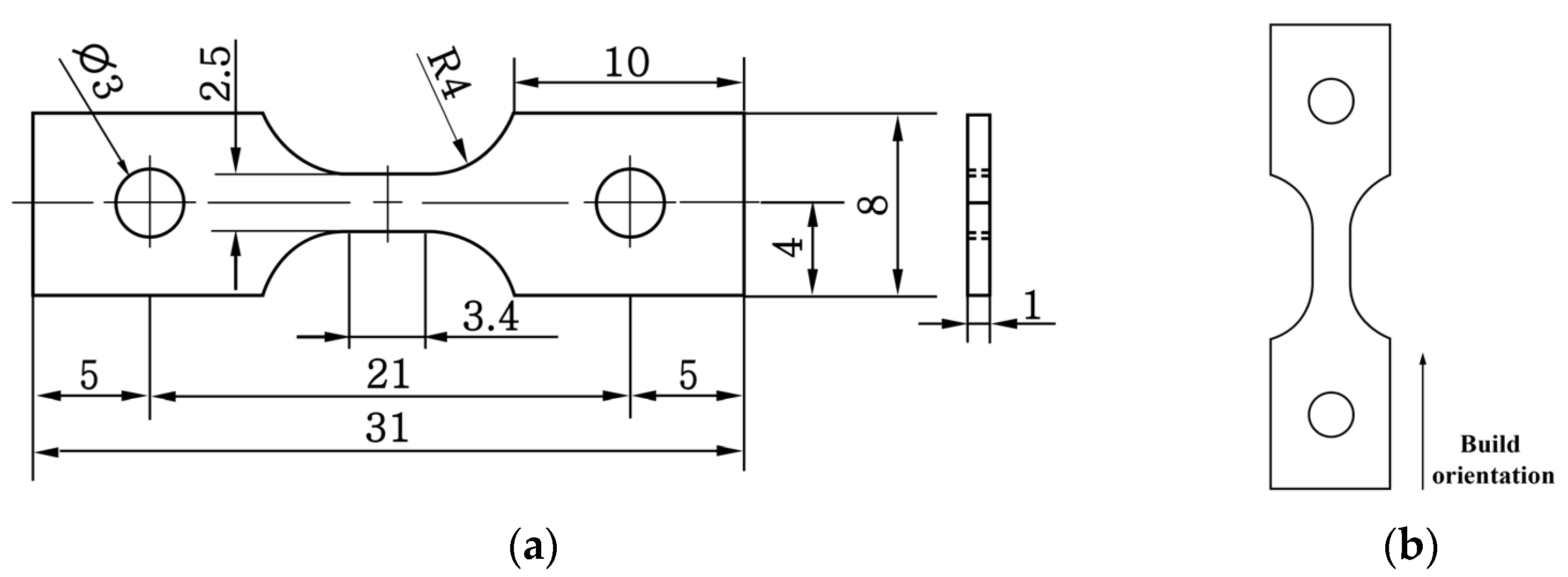
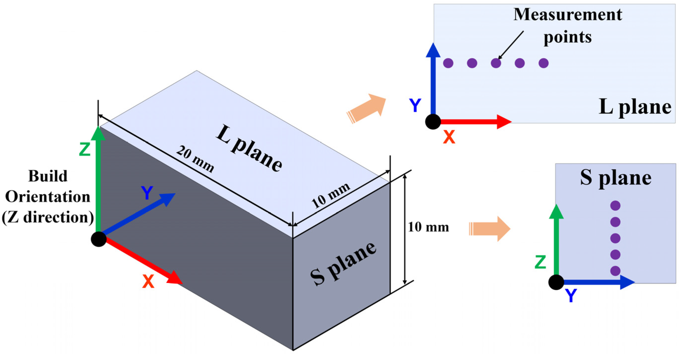
In this study, a metallic filament (Ultrafuse 316L, BASF) was used to fabricate two kinds of specimens for hardness and tensile strength testing. Table 1 provides basic information about the metallic filament. In the fabrication of specimens, an open-source-based ME machine (LUGOLABS, Korea) was utilized. Recommended process parameters provided by the metallic filament manufacturer are shown in Table 2. Of the three build orientations shown in Figure 1, the upright one was selected because it was orthogonal to the load direction in the tensile test, and the bonding force between layers is a dominant parameter for the determination of the tensile strength in the load direction [36,37]. The infill pattern in a layer is shown in Figure 2. A raster angle of ±45° was used for the infill pattern. The hardness specimens measured 10 mm × 20 mm × 10 mm; the tensile specimens were fabricated with the dimensions shown in Figure 3.

2.2. WIP Equipment and Process Parameters

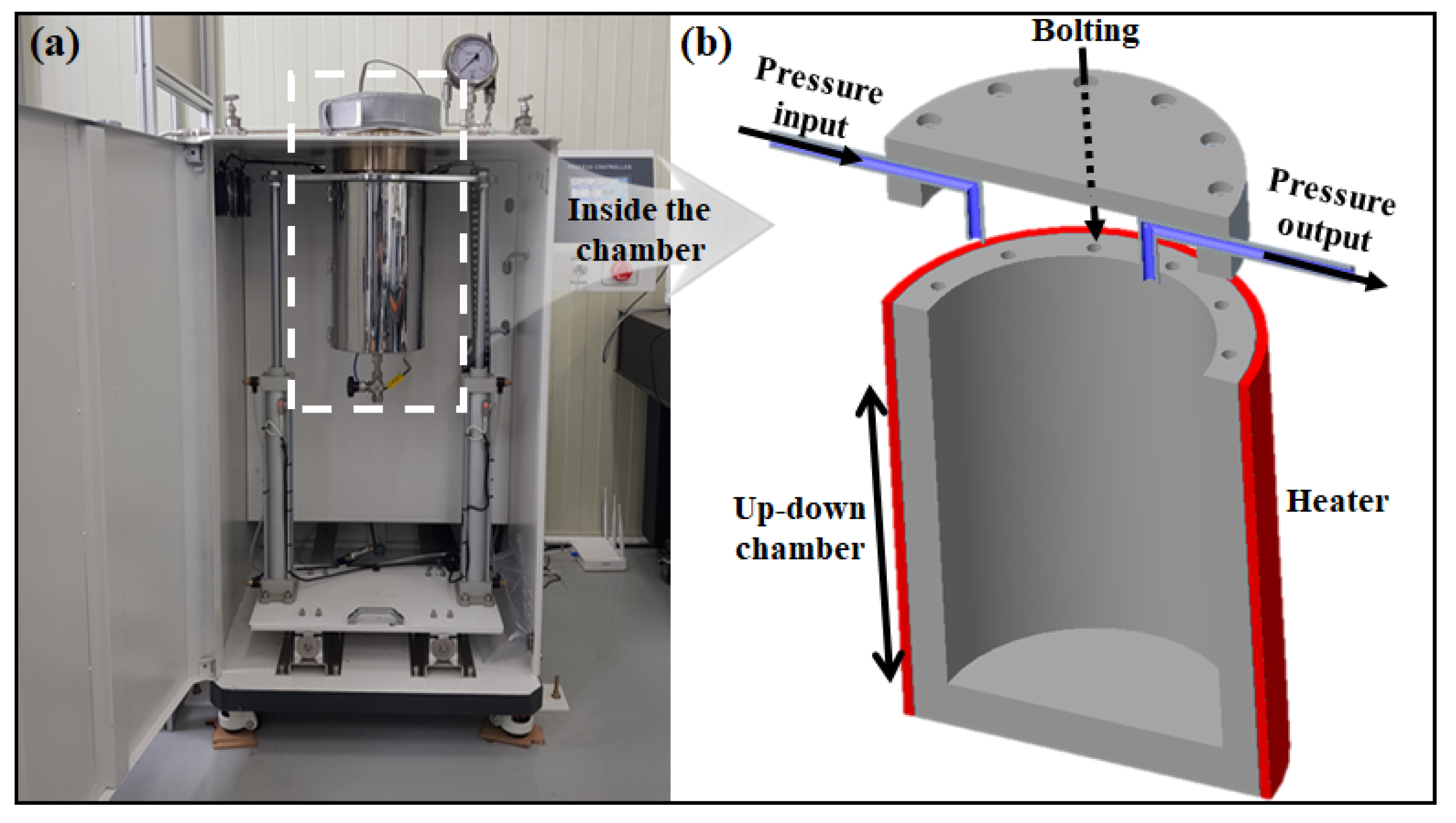
The WIP process as shown in Figure 4 uses temperature and pressure simultaneously. Before the process, all specimens were vacuum-packed and placed in the chamber. Nitrogen gas was used to deliver the pressure isostatically from 1 to 90 bar. The temperature inside the chamber was increased by the external heater. The WIP process was performed with a green part after completing the specimen fabrication as shown in Figure 5.
Before determining the temperature, the metallic filament was analyzed by mass spectroscopy and the matrix polymer was identified as polyoxymethylene (POM). Based on this result, the temperature for the WIP process was set to 180 °C, close to the melting temperature of POM. Based on previous work [34], a pressure of 90 bar was used. Figure 6 shows the detailed process profile of WIP.

2.3. Debinding and Sintering

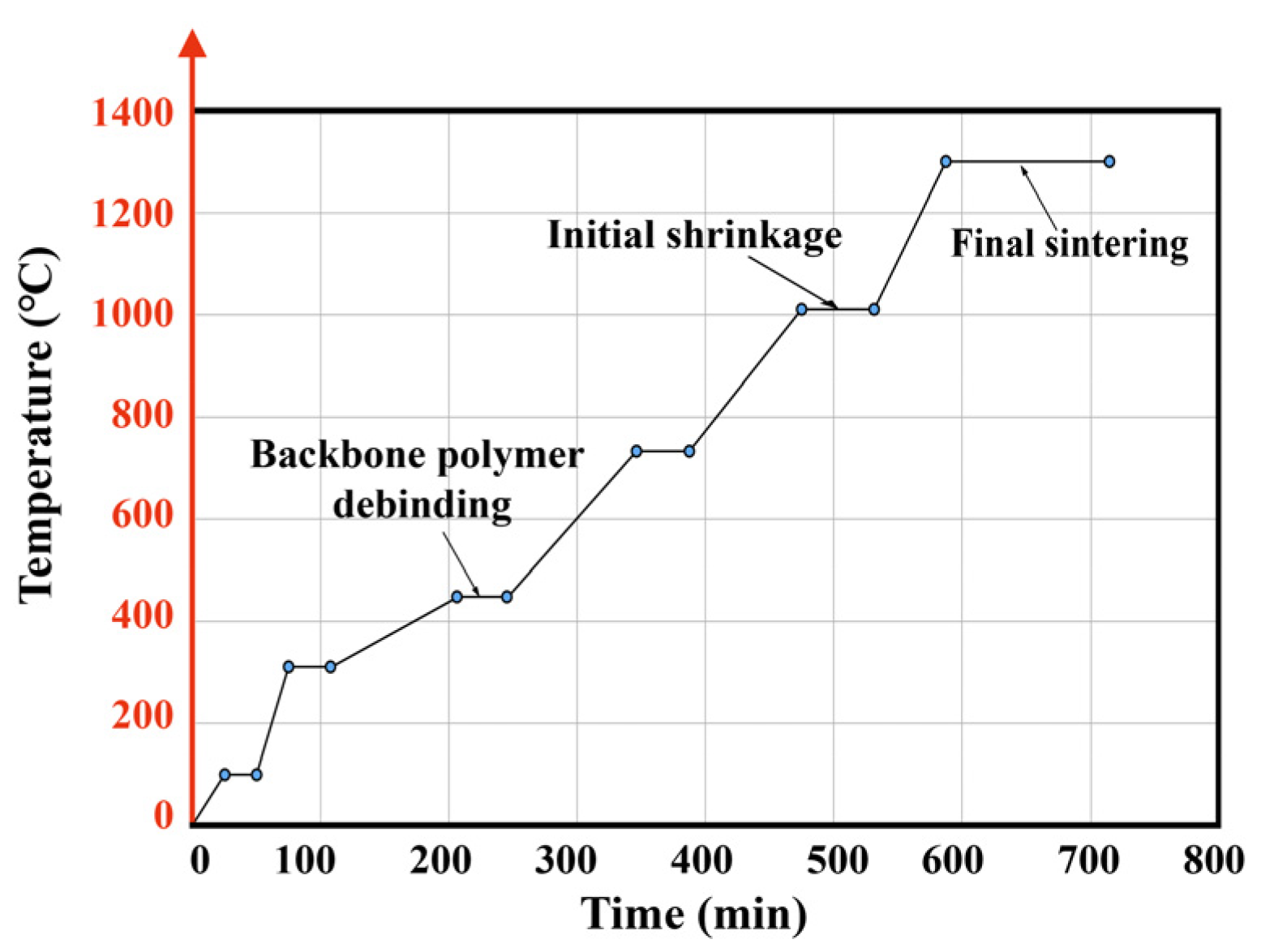
The final (white) specimens were obtained after debinding and sintering. In the debinding process, a self-manufactured furnace was used. The final specimens were treated for 8 h at 130 °C under a mixed atmosphere of nitrogen and nitric acid gas. Sintering was also performed in a self-made box-type furnace under a 99.999% hydrogen atmosphere. Figure 7 shows the temperature profile for the sintering process. For stable sintering, the heating temperature profile was divided into six stages; the holding time in each stage was at least 30 min to ensure a homogenous temperature distribution within the specimen [38].

2.4. Measurement of Mechanical Properties

Tensile and hardness tests were performed to evaluate the influence of WIP on the mechanical properties of the specimens. For the tensile test, a universal testing machine (Minos-300S, MTDI, South Korea) was used. Specimens were fabricated as shown in Figure 2 and tests were performed at load speed 0.36 mm/min. Displacement and loading force were measured by linear encoder with 0.5 um precision and load cell, respectively. Representative values of tensile strength were obtained by averaging three time measurements.
For the hardness tests, specimens were cut with a diamond cut-off wheel and cold-mounted. The measurements of hardness were conducted at the places shown in Figure 8. In each place, five measurements were performed to obtain an average hardness. Hardness was measured in two ways. On the microscopic scale, Vickers hardness was measured with a HM-200 Vickers hardness tester with an indent load of 0.5 kgf and dwell time of 12 s. On the macroscopic scale, Rockwell hardness was measured with a KBW 150RCW hardness tester with an indent load of 60 kgf and dwell time of 7 s.

2.5. Microstructural Analysis

Specimens were manufactured with dimensions 10 mm × 10 mm × 10 mm. To analyze the cross-section, each specimen was cut in the orthogonal to the build direction (L plane). The cross-section was polished using #100, #400, #800, #1200, and #2400 grit SIC waterproof abrasive paper. Then, micro-polishing was performed with 3 µm, 1 µm diamond and oxide polishing suspensions and tegramin-30 (Struers, Denmark). A VHX-5000 optical microscope (OM) and Quanta FEG-250 scanning electron microscope (SEM) were used for observing the microstructure. In addition, the distribution of chemical elements in each specimen was characterized using SEM with an energy-dispersive spectroscopy (EDS).

3. Results

3.1. Tensile Strength

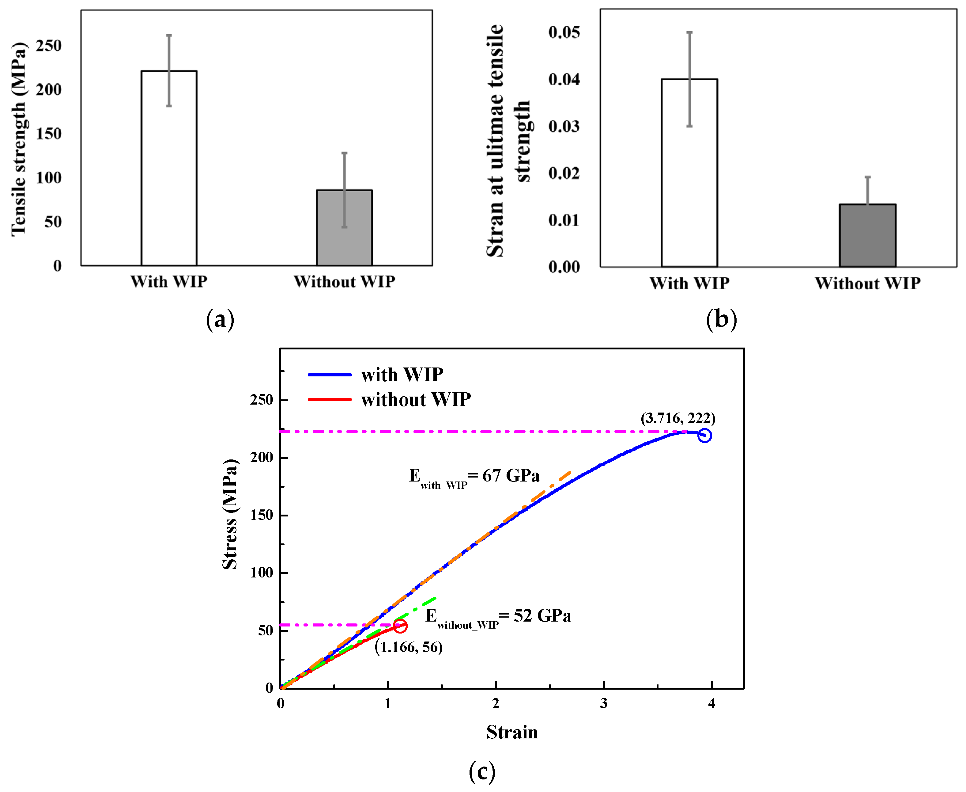
Tensile testing was performed to investigate the change in mechanical properties due to the WIP process. The results are shown in Figure 9. The tensile strength of the WIP-processed specimen was 2.5 times that of the non-WIP-processed specimen. Additionally, the strain at the ultimate tensile strength was 4 times that of the non-WIP-processed specimen. However, for both tensile strength and strain, the deviation between three specimens was large because of irregular pores that existed after sintering. Specimens produced by the ME process have 100% filling in the green state, but it is thought that sintering of the remaining metal powders does not achieve 100% density after the polymer evaporates. This leads the formation of many pores within specimens, resulting in the large deviations of the tensile strength and stain. The tensile strength of the WIP specimen showed many lower values compared to the strength of the bulk material of general SUS 316L. This means that the reduction of pores generated during the WIP process is the most important factor in improving mechanical properties. Therefore, it is also necessary to optimize the process parameters of the printing process to minimize pore generation caused by the vaporization of the polymer material during sintering.

3.2. Hardness

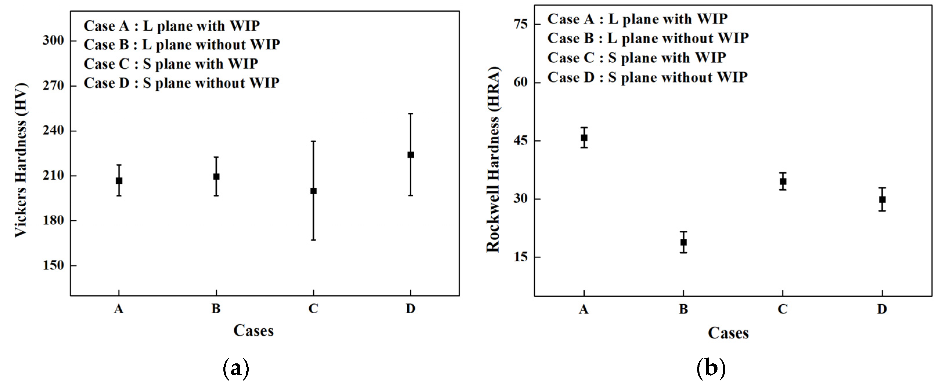
Vickers and Rockwell hardness tests were performed to investigate the variation of the effect of WIP with scale as shown in Figure 10. The microscopic-scale Vickers hardness showed no significant change due to WIP but the deviation of the hardness along the build direction (at the S plane) was larger than the deviation of the results obtained from the L plane. At the macroscopic scale, the measurement results in all cases were different. In the L plane, the difference between the cases with and without WIP was larger than that along the building direction. This means that the Rockwell hardness in the L plane was more affected by the WIP process. Cherry et al. reported that an increase in porosity leads to a decrease in material hardness [39]. This is due to the collapse of the pores within the material under indenter load. In specimens with relatively large pores, the hardness sensitivity increases with a larger indenter. Hence, in the Rockwell hardness test, the hardness changed. These results indicate that the Rockwell hardness test is more effective in the study of the effect of pores on hardness.

3.3. Microstructural Analysis

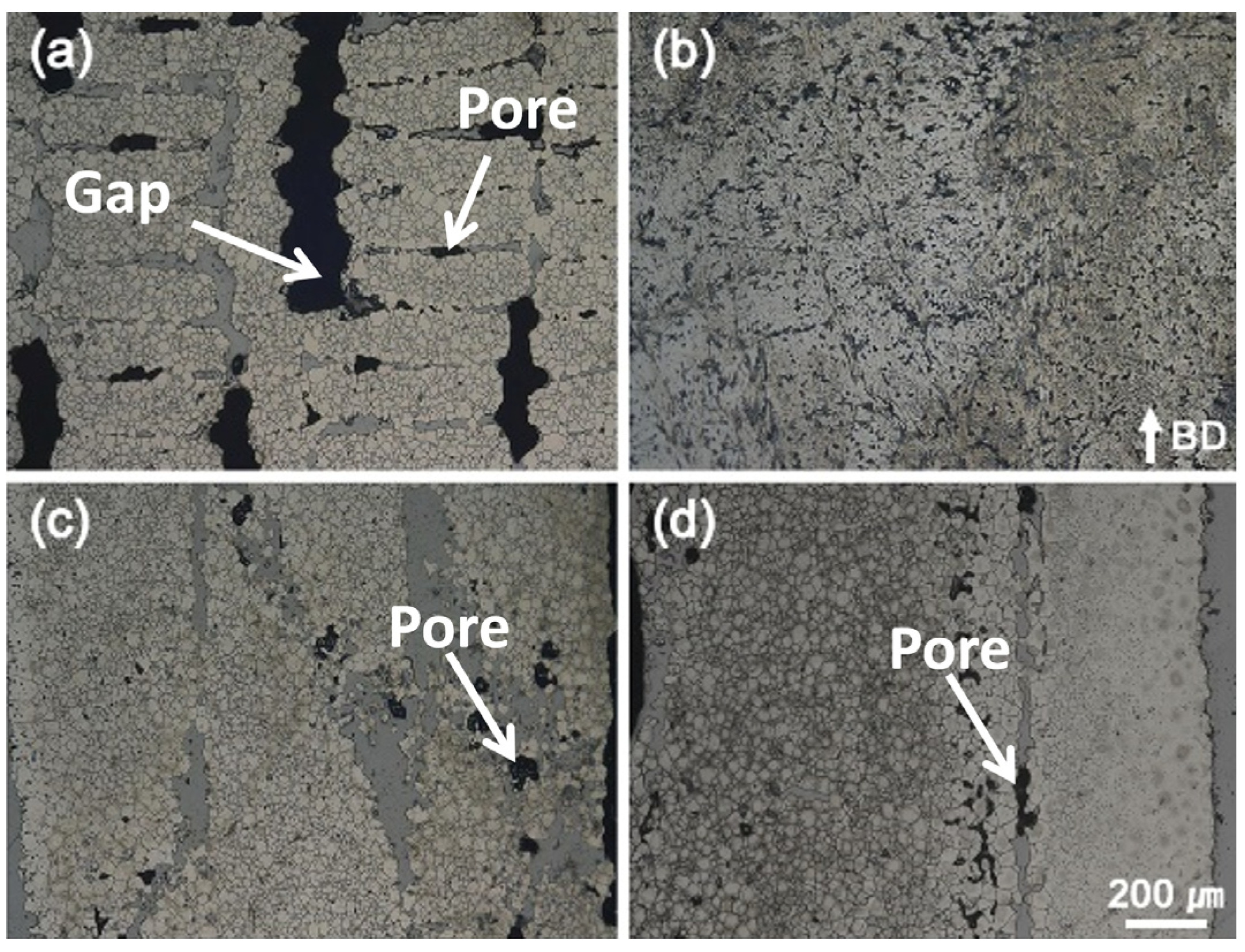
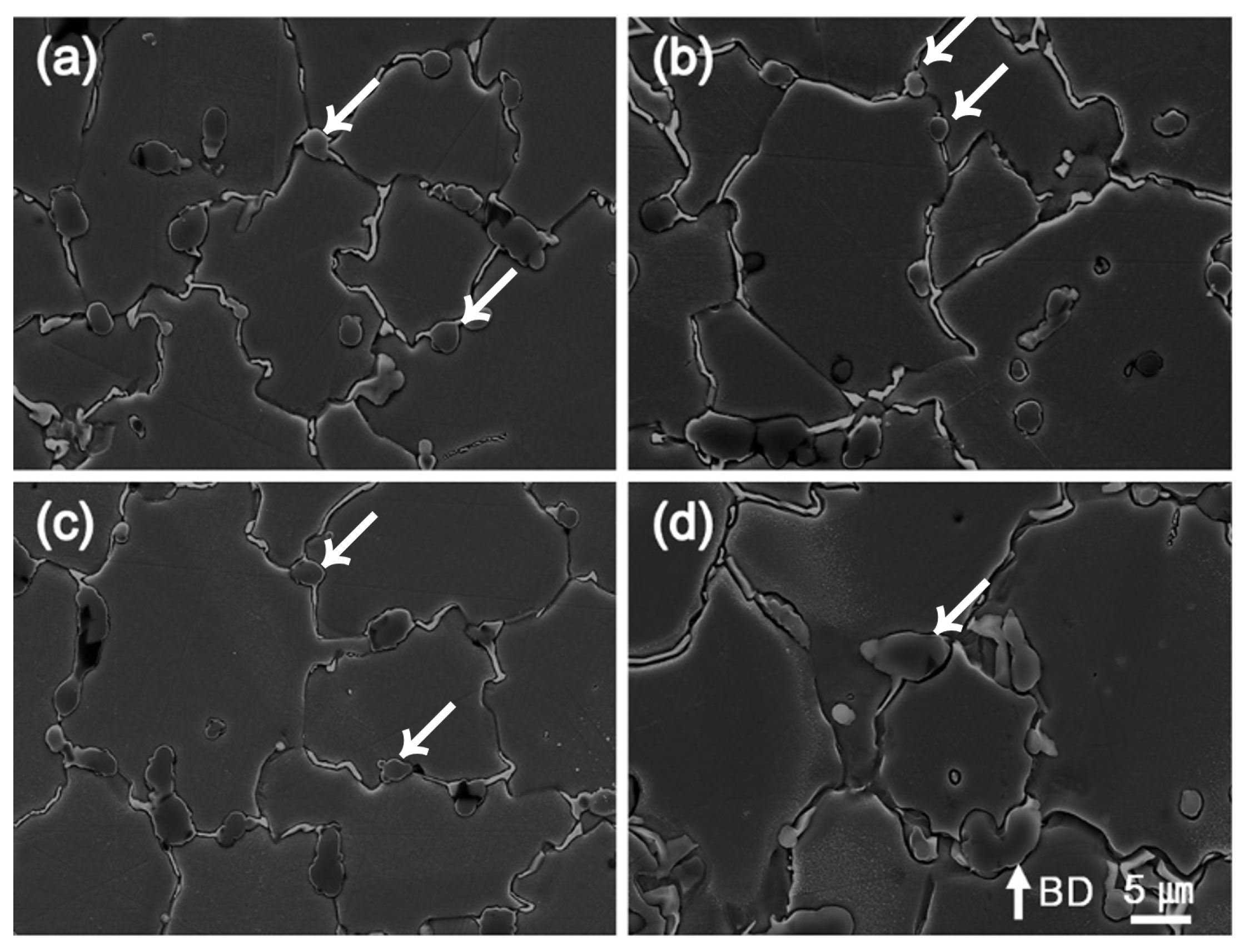
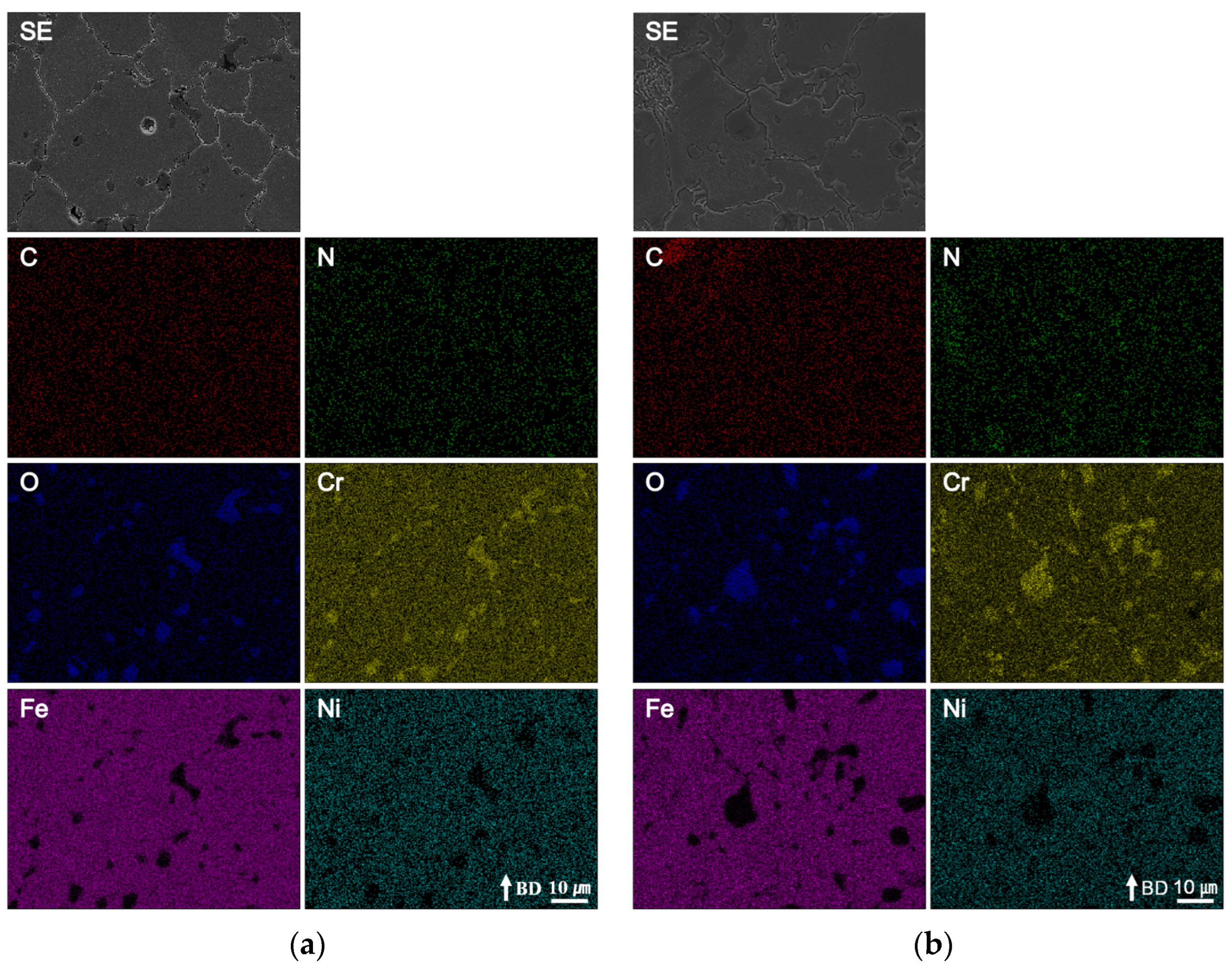
The OM images in Figure 11 show the macrostructures on the two planes with and without WIP. In the S-plane without WIP, irregular pores and gaps formed between the inter-layers (Figure 11a). By contrast, in the L-plane without WIP (Figure 11c), although large pores due to lack of fusion did not appear, micropores existed nevertheless. However, after WIP, these critical large defects were dramatically diminished (Figure 11b,d). Figure 12 shows the microstructure obtained by means of SEM. Round secondary phase particles at the grain boundaries (indicated by arrows in Figure 12) and even in the grains were observed in both specimens. Moreover, the segregated secondary phase at the grain boundary is observable in Figure 12 with white color. The chemical composition of the secondary-phase particles is shown by the elemental maps in Figure 13 and Figure 14; it was characterized by C, N, O, Cr, Fe, and Ni. The round particles mainly consisted of Cr and O, like in the chrome oxide phase; the segregated particles were mainly Cr. For these secondary phase particles formed during the sintering process [40], a significant difference in the characteristics such as size, shape and distribution was not found between the cases with and without WIP.

4. Discussion

The main reasons for introducing the WIP process into the fabrication of metal parts from metal filament is to reduce the pores generated inside the exterior wall of the green part and to reduce the gap between the metal powders in the layered metal filament, possibly improving the density of the exterior wall in the white part and thus the mechanical properties. In this section, the effect of WIP on the mechanical properties and microstructure is discussed.

4.1. WIP Effect on Mechanical Properties

From the results of the tensile and hardness tests reported in Section 3, it appears that the WIP process improves tensile strength and ductility but has little effect on hardness.
Park et al. reported that WIP improved the mechanical properties by reducing the pores that occur in the polymer-based ME process and increasing the bonding area between layers or between the extruded strands of the polymers in a plane. In addition, it has been reported that the increase in the bonding force between layers improves the anisotropy that commonly occurs in parts produced by AM [41]. The effect of WIP on the mechanical properties is due to the influence of the temperature and pressure applied during the process on the flow of the polymer. The polymer flow is the reason that the authors first became interested in the WIP process. It seemed possible that, if WIP were introduced into metal ME, the polymer flow by WIP would reduce the distance between metal powders included in the filament, and a dense final part with higher tensile strength could be obtained after debinding and sintering.
Figure 15 shows the fractured surface of the tensile specimen. In Figure 15a, which shows the cross-section of a tensile specimen treated with WIP, it can be seen that many pores were irregularly distributed in the interior, whereas there were relatively few pores near the outer wall. By contrast, in the fractured surface of the non-WIP specimen (Figure 15b), a large number of pores were generated along the extrusion path. The pores continuously observed along the extrusion path reached to near the outer wall. This continuous distribution of pores made it easy for cracks from the outside wall to propagate to the interior; the number and the distribution pattern of pores in the part seemed to affect the direction and speed of crack propagation during tensile testing. The distribution of pores could be affected by the WIP process. This may also explain the large difference in strain. The measured tensile strength (which was 2.5 times greater with WIP treatment) strongly aligns with this idea.
As shown in Figure 15, if the pore generation along the extrusion path affects the mechanical properties, the mechanical properties can be improved by changing the infill pattern.
In the case of a concentric pattern with an infill path parallel to the contour path, the pore formations with an extrusion path are perpendicular to the direction of crack propagation, which slows down the crack propagation and potentially improves the mechanical properties. Dezaki et al. reported that the concentric pattern showed the highest strength in tensile tests with various infill patterns [38]. The introduction of the WIP process to the metal filament ME process can be expected to further enhance the effect of the infill pattern.
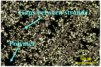
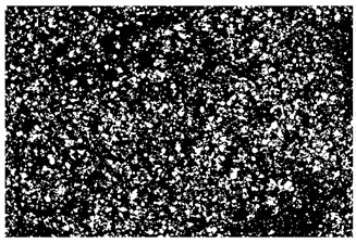
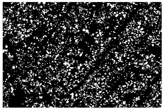
Table 3 shows the distribution of metal powders in green parts for the two cases (with WIP and without WIP) and the area fraction of metal powders. In the “without WIP” case, gaps between strands are formed along the extrusion path and non-uniform powder distributions are clearly observed. However, the gaps cannot be found in the WIPed specimens. This means that the WIP process can help to eliminate the gaps between strands. In addition, the distribution uniformity of metal powders was improved as shown in Table 3. To evaluate the uniformity, ImageJ software was used. Original images were converted into 8 images, and then the area fraction of metal powders was measured. The values of the area fraction of metal powders were 26.62 and 17.16%, respectively. Although the measured area fraction could have some deviation depending on the area taken, the area fraction of metal powders clearly increases with the WIP process.
The increase in the area fraction of metal powders can be obtained by measuring the density. Densities of green and white parts treated without the WIP process are 4.390 and 6.451 g/cm3, respectively, while densities of green and white parts with the WIP process are 4.774 and 6.957 g/cm3, respectively.
Figure 16 shows the change in properties with/without the WIP process. From Figure 16, we conclude that the area fraction of metal powders should be increased to improve mechanical properties and the improvement in mechanical properties can verify the effectiveness of the WIP process in the metal filament ME process. This result is consistent with the findings of Singh et al. [42].
Hence, in the optimization of the WIP process, the density of the green part should be considered. However, the WIP process conditions used in this study were determined based on the authors’ previous studies, considering the material properties of the binder polymer POM and dimensions and shape of the specimen. In the future, studies on the optimization of the WIP process can be conducted.

4.2. Considerations for the WIP Process Parameters in Metal ME

The optimization of the WIP process parameters is beyond the scope of this work. However, to increase the understanding of the metal ME process, it is necessary to briefly discuss the factors to be considered in determining temperature in the WIP process.
The determination of the WIP-process temperature strongly depends on the characteristics of the substrate material (in this case, POM). Higher temperature is correlated with higher polymer fluidity: to increase the WIP effect, the temperature must be increased. However, greater fluidity of a material implies greater possibility of deformation due to external loads (or to its own weight). Therefore, in order to increase the efficiency of the WIP process, it is important to determine the highest temperature at which deformation does not occur.
This problem must be considered when WIP is introduced into the metal ME process. A polymer containing metal powder has a higher thermal conductivity than a pure polymer, so that the heat applied during WIP process rapidly diffuses into the interior, and deformation of the part occurs at a lower temperature due to the rapid heat diffusion into the part [43]. In other words, in terms of deformation, material that includes metal powder is more sensitive to temperature than pure polymer is. This temperature sensitivity varies depending on the shape of the part: a thin-walled part deforms at a lower temperature than a thick part. Setting the proper WIP temperature becomes more difficult when a part consists of sub-parts with varying thicknesses. In addition, the temperature sensitivity to the deformation also varies depending on the kind of metal powder used.
The Introduction of the WIP process into metal ME obviously helps to improve the mechanical properties of the finished part. However, there is also a disadvantage in that more variables need to be considered to make the process more efficient. This will be further explored in future studies.

5. Conclusions

In this study, experiments were conducted to find out the change in mechanical properties when WIP is introduced into an ME process that uses a filament containing metal powder. The results could be summarized as follows:
  • In the specimens used in this study, the tensile strength increased by a factor of 2.5 with WIP treatment. This shows that the specimen-manufacturing process conditions contribute to increasing the tensile strength, even considering the lack of optimization.
  • The strain at ultimate tensile strength also increased fourfold with WIP. This was because, in the absence of WIP treatment, the large number of pores played an important role in crack initiation even at small strain and produced brittle behavior. If the process conditions were optimized, the effect of WIP treatment would be reduced, but not eliminated.
  • Two types of hardness tests were performed. The Rockwell (macroscopic) hardness was affected by WIP (probably through pore generation); the Vickers (microscopic) hardness was not, because the WIP process was not performed at a high enough temperature to change of the microstructure of the metal.
  • At the grain boundary, there were round secondary-phase particles composed of chrome oxide. Although chrome oxide exists on the surface of a typical SUS material, it seems that in this case, the chrome oxide phase only on the surface of the printed strand was impregnated inside.
The main purpose of this study was to confirm the possibility of improving mechanical properties by the introduction of the WIP process. Although such an improvement was confirmed, the conditions used in this study were not optimal ones but just effective conditions for individual processes. In the future, the authors plan to study optimization conditions, as well as the relationship between design factors and process parameters in the metal-filament extrusion process with WIP.

Author Contributions

Writing—original draft preparation, B.-Y.C.; data curation, B.-Y.C., S.-J.P., S.-J.H. and H.-G.K.; funding acquisition, Y.S.; writing—review and editing, I.-H.A. and W.-C.C. All authors have read and agreed to the published version of the manuscript.

Funding

This study has been conducted with the support of the Korea Institute of Industrial Technology as “Development of root technology for multi-product flexible production (KITECH EO-20-0015)”.

Conflicts of Interest

The authors declare no conflict of interest.

References

  1. Yadav, D.K.; Srivastava, R.; Dev, S. Design & fabrication of ABS part by FDM for automobile application. Mater. Today Proc. 2020, 26, 2089–2093. [Google Scholar] [CrossRef]
  2. Jiang, J. A novel fabrication strategy for additive manufacturing processes. J. Clean. Prod. 2020, 272, 122916. [Google Scholar] [CrossRef]
  3. Ali, M.; Sari, R.K.; Sajjad, U.; Sultan, M.; Ali, H.M. Effect of annealing on microstructures and mechanical properties of PA-12 lattice structures proceeded by multi jet fusion technology. Addit. Manuf. 2021, 47, 102285. [Google Scholar] [CrossRef]
  4. Kim, S.H.; Yeon, S.-M.; Lee, J.H.; Kim, Y.W.; Lee, H.; Park, J.; Lee, N.-K.; Choi, J.P.; Aranas, C., Jr.; Lee, Y.J.; et al. Additive manufacturing of a shift block via laser powder bed fusion: The simultaneous utilisation of optimised topology and a lattice structure. Virtual Phys. Prototyp. 2020, 15, 1–21. [Google Scholar] [CrossRef]
  5. Park, S.J.; Lee, J.H.; Yang, J.; Heogh, W.; Kang, D.; Yeon, S.M.; Kim, S.H.; Hong, S.; Son, Y.; Park, J. Lightweight injection mold using additively manufactured Ti-6Al-4V lattice structures. J. Manuf. Process. 2022, 79, 759–766. [Google Scholar] [CrossRef]
  6. Frandsen, C.S.; Nielsen, M.M.; Chaudhuri, A.; Jayaram, J.; Govindan, K. In search for classification and selection of spare parts suitable for additive manufacturing: A literature review. Int. J. Prod. Res. 2019, 58, 970–996. [Google Scholar] [CrossRef]
  7. Park, S.J.; Lee, J.E.; Park, J.; Lee, N.-K.; Son, Y.; Park, S.-H. High-temperature 3D printing of polyetheretherketone products: Perspective on industrial manufacturing applications of super engineering plastics. Mater. Des. 2021, 211, 110163. [Google Scholar] [CrossRef]
  8. Park, S.J.; Lee, J.E.; Lee, H.B.; Park, J.; Lee, N.-K.; Son, Y.; Park, S.-H. 3D printing of bio-based polycarbonate and its potential applications in ecofriendly indoor manufacturing. Addit. Manuf. 2019, 31, 100974. [Google Scholar] [CrossRef]
  9. Peterson, A.M. Review of acrylonitrile butadiene styrene in fused filament fabrication: A plastics engineering-focused perspective. Addit. Manuf. 2019, 27, 363–371. [Google Scholar] [CrossRef]
  10. Manoj, A.; Bhuyan, M.; Banik, S.R.; Sankar, M.R. Review on particle emissions during fused deposition modeling of acrylonitrile butadiene styrene and polylactic acid polymers. Mater. Today Proc. 2021, 44, 1375–1383. [Google Scholar] [CrossRef]
  11. Rinaldi, M.; Cecchini, F.; Pigliaru, L.; Ghidini, T.; Lumaca, F.; Nanni, F. Additive Manufacturing of Polyether Ether Ketone (PEEK) for Space Applications: A Nanosat Polymeric Structure. Polymers 2020, 13, 11. [Google Scholar] [CrossRef] [PubMed]
  12. Çevik, Ü.; Kam, M.; Zare, E.N. A Review Study on Mechanical Properties of Obtained Products by FDM Method and Metal/Polymer Composite Filament Production. J. Nanomater. 2020, 1–9. [Google Scholar] [CrossRef]
  13. Liu, Z.; Lei, Q.; Xing, S. Mechanical characteristics of wood, ceramic, metal and carbon fiber-based PLA composites fabricated by FDM. J. Mater. Res. Technol. 2019, 8, 3741–3751. [Google Scholar] [CrossRef]
  14. Tosto, C.; Tirillò, J.; Sarasini, F.; Cicala, G. Hybrid Metal/Polymer Filaments for Fused Filament Fabrication (FFF) to Print Metal Parts. Appl. Sci. 2021, 11, 1444. [Google Scholar] [CrossRef]
  15. Rosnitschek, T.; Seefeldt, A.; Alber-Laukant, B.; Neumeyer, T.; Altstädt, V.; Tremmel, S. Correlations of Geometry and Infill Degree of Extrusion Additively Manufactured 316L Stainless Steel Components. Materials 2021, 14, 5173. [Google Scholar] [CrossRef]
  16. Ye, H.; Liu, X.Y.; Hong, H. Fabrication of metal matrix composites by metal injection molding—A review. J. Mater. Process. Technol. 2008, 200, 12–24. [Google Scholar] [CrossRef] [Green Version]
  17. Safarian, A.; Subaşi, M.; Karataş, Ç. The effect of sintering parameters on diffusion bonding of 316L stainless steel in inserted metal injection molding. Int. J. Adv. Manuf. Technol. 2016, 89, 2165–2173. [Google Scholar] [CrossRef]
  18. Ye, H.; Liu, X.Y.; Hong, H. Sintering of 17-4PH stainless steel feedstock for metal injection molding. Mater. Lett. 2008, 62, 3334–3336. [Google Scholar] [CrossRef] [Green Version]
  19. Singh, P.; Balla, V.K.; Gokce, A.; Atre, S.V.; Kate, K.H. Additive manufacturing of Ti-6Al-4V alloy by metal fused filament fabrication (MF3): Producing parts comparable to that of metal injection molding. Prog. Addit. Manuf. 2021, 6, 593–606. [Google Scholar] [CrossRef]
  20. Yu, P.C.; Li, Q.F.; Fuh, J.Y.H.; Li, T.; Ho, P.W. Micro injection molding of micro gear using nano-sized zirconia powder. Microsyst. Technol. 2008, 15, 401–406. [Google Scholar] [CrossRef]
  21. Thomas-Vielma, P.; Cervera, A.; Levenfeld, B.; Várez, A. Production of alumina parts by powder injection molding with a binder system based on high density polyethylene. J. Eur. Ceram. Soc. 2008, 28, 763–771. [Google Scholar] [CrossRef]
  22. Tao, Y.; Kong, F.; Li, Z.; Zhang, J.; Zhao, X.; Yin, Q.; Xing, D.; Li, P. A review on voids of 3D printed parts by fused filament fabrication. J. Mater. Res. Technol. 2021, 15, 4860–4879. [Google Scholar] [CrossRef]
  23. Solomon, I.J.; Sevvel, P.; Gunasekaran, J. A review on the various processing parameters in FDM. Mater. Today Proc. 2020, 37, 509–514. [Google Scholar] [CrossRef]
  24. Gao, G.; Xu, F.; Xu, J.; Tang, G.; Liu, Z. A Survey of the Influence of Process Parameters on Mechanical Properties of Fused Deposition Modeling Parts. Micromachines 2022, 13, 553. [Google Scholar] [CrossRef] [PubMed]
  25. Carneiro, O.S.; Silva, A.F.; Gomes, R. Fused deposition modeling with polypropylene. Mater. Des. 2015, 83, 768–776. [Google Scholar] [CrossRef]
  26. Kuznetsov, V.E.; Solonin, A.N.; Urzhumtsev, O.D.; Schilling, R.; Tavitov, A.G. Strength of PLA Components Fabricated with Fused Deposition Technology Using a Desktop 3D Printer as a Function of Geometrical Parameters of the Process. Polymers 2018, 10, 313. [Google Scholar] [CrossRef] [Green Version]
  27. Aloyaydi, B.A.; Sivasankaran, S.; Ammar, H.R. Influence of infill density on microstructure and flexural behavior of 3D printed PLA thermoplastic parts processed by fusion deposition modeling. AIMS Mater. Sci. 2019, 6, 1033–1048. [Google Scholar] [CrossRef]
  28. Rayegani, F.; Onwubolu, G.C. Fused deposition modelling (FDM) process parameter prediction and optimization using group method for data handling (GMDH) and differential evolution (DE). Int. J. Adv. Manuf. Technol. 2014, 73, 509–519. [Google Scholar] [CrossRef]
  29. Saniman, M.N.F.; Hashim, M.H.M.; Mohammad, K.A.; Wahid, K.A.A.; Muhamad, W.M.W.; Mohamed, N.H.N. Tensile Characteristics of Low Density Infill Patterns for Mass Reduction of 3D Printed Polylactic Parts. Int. J. Automot. Mech. Eng. 2020, 17, 7927–7934. [Google Scholar] [CrossRef]
  30. Dezaki, M.L.; Ariffin, M.; Serjouei, A.; Zolfagharian, A.; Hatami, S.; Bodaghi, M. Influence of Infill Patterns Generated by CAD and FDM 3D Printer on Surface Roughness and Tensile Strength Properties. Appl. Sci. 2021, 11, 7272. [Google Scholar] [CrossRef]
  31. Meng, Q.; Gu, Y.; Luo, L.; Wang, S.; Li, M.; Zhang, Z. Annealing effect on crystalline structure and mechanical properties in long glass fiber reinforced polyamide 66. J. Appl. Polym. Sci. 2017, 134, 44832. [Google Scholar] [CrossRef]
  32. Wang, J.; Tan, Q.; Wang, K.; Yao, S.; Peng, Y.; Rao, Y. A heat-press-treatment method for 3D printed thin-walled composite structures with improved interfacial and compressive properties. Polym. Compos. 2022, 34, 8471–8482. [Google Scholar] [CrossRef]
  33. Bhandari, S.; Lopez-Anido, R.A.; Gardner, D.J. Enhancing the interlayer tensile strength of 3D printed short carbon fiber reinforced PETG and PLA composites via annealing. Addit. Manuf. 2019, 30, 100922. [Google Scholar] [CrossRef]
  34. Park, S.J.; Son, Y.; Ahn, I.H. Influence of warm isostatic press (WIP) process parameters on mechanical properties of additively manufactured acrylonitrile butadiene styrene (ABS) parts. Int. J. Adv. Manuf. Technol. 2022, 122, 3311–3322. [Google Scholar] [CrossRef]
  35. O’Connor, H.J.; Dowling, D.P. Low-pressure additive manufacturing of continuous fiber-reinforced polymer composites. Polym. Compos. 2019, 40, 4329–4339. [Google Scholar] [CrossRef]
  36. Zhao, Y.; Chen, Y.; Zhou, Y. Novel mechanical models of tensile strength and elastic property of FDM AM PLA materials: Experimental and theoretical analyses. Mater. Des. 2019, 181, 108089. [Google Scholar] [CrossRef]
  37. Yao, T.; Ye, J.; Deng, Z.; Zhang, K.; Ma, Y.; Ouyang, H. Tensile failure strength and separation angle of FDM 3D printing PLA material: Experimental and theoretical analyses. Compos. Part B Eng. 2020, 188, 107894. [Google Scholar] [CrossRef]
  38. Wang, W.; Zhao, G.; Wu, X.; Zhai, Z. The effect of high temperature annealing process on crystallization process of polypropylene, mechanical properties, and surface quality of plastic parts. J. Appl. Polym. Sci. 2015, 132, 42773. [Google Scholar] [CrossRef]
  39. Cherry, J.A.; Davies, H.M.; Mehmood, S.; Lavery, N.P.; Brown, S.G.R.; Sienz, J. Investigation into the effect of process parameters on microstructural and physical properties of 316L stainless steel parts by selective laser melting. Int. J. Adv. Manuf. Technol. 2015, 76, 869–879. [Google Scholar] [CrossRef] [Green Version]
  40. Wagner, M.A.; Engel, J.; Hadian, A.; Clemens, F.; Rodriguez-Arbaizar, M.; Carreño-Morelli, E.; Wheeler, J.M.; Spolenak, R. Filament extrusion-based additive manufacturing of 316L stainless steel: Effects of sintering conditions on the microstructure and mechanical properties. Addit. Manuf. 2022, 59, 103147. [Google Scholar] [CrossRef]
  41. Park, S.J.; Son, Y.; Ahn, I.H. Reducing anisotropy of a part fabricated by material extrusion via warm isostatic pressure (WIP) process. Addit. Manuf. 2022, 55, 102841. [Google Scholar] [CrossRef]
  42. Singh, P.; Balla, V.K.; Atre, S.V.; German, R.M.; Kate, K.H. Factors affecting properties of Ti-6Al-4V alloy additive manufactured by metal fused filament fabrication. Powder Technol. 2021, 386, 9–19. [Google Scholar] [CrossRef]
  43. Hwang, S.; Reyes, E.I.; Moon, K.-S.; Rumpf, R.C.; Kim, N.S. Thermo-mechanical Characterization of Metal/Polymer Composite Filaments and Printing Parameter Study for Fused Deposition Modeling in the 3D Printing Process. J. Electron. Mater. 2014, 44, 771–777. [Google Scholar] [CrossRef]
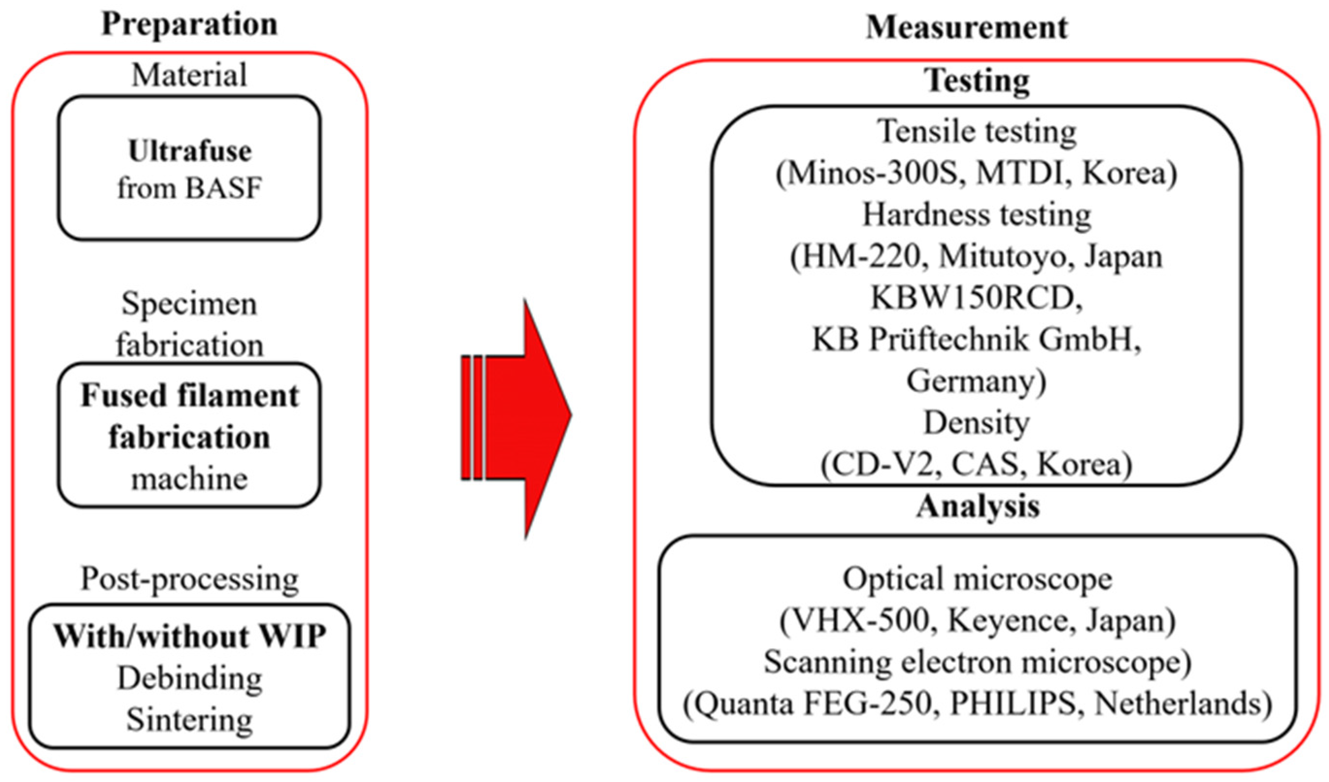
Figure 1. Preparation and measurements.
Applsci 12 12240 g001
Figure 2. Fabrication of specimen from metallic filament: (a) generated path in a plane, (b) build orientation.
Applsci 12 12240 g002
Figure 3. Tensile specimen: (a) dimensions [mm], (b) build orientation.
Applsci 12 12240 g003
Figure 4. (a) Photograph of the equipment and (b) schematic of the cross section for the WIP process adapted with permission from [34].
Applsci 12 12240 g004
Figure 5. Schematic illustration of metallic fused deposition modeling.
Applsci 12 12240 g005
Figure 6. Detailed profile of the warm isostatic press process.
Applsci 12 12240 g006
Figure 7. Temperature profile for sintering process.
Applsci 12 12240 g007
Figure 8. Dimensions of hardness test specimen, and definition of S and L planes and measurement points.
Applsci 12 12240 g008
Figure 9. Results of tensile test with and without warm isostatic press (WIP): (a) tensile strength; (b) strain at ultimate tensile strength; (c) strain-stress curve.
Applsci 12 12240 g009
Figure 10. Measurement of (a) Vickers (microscopic) and (b) Rockwell (macroscopic) hardness with and without WIP.
Applsci 12 12240 g010
Figure 11. Optical micrographs of specimens at (a) S plane without WIP; (b) S plane with WIP; (c) L plane without WIP; (d) L plane with WIP.
Applsci 12 12240 g011
Figure 12. Microstructural SEM images of specimens and secondary phase particles (white arrows) at (a) L plane without WIP; (b) L plane with WIP; (c) S plane without WIP; (d) S plane with WIP. (WIP: warm isostatic pressure.)
Applsci 12 12240 g012
Figure 13. Elemental maps at the specimen L plane: (a) without and (b) with warm isostatic press. (SE: secondary-electron SEM image.)
Applsci 12 12240 g013
Figure 14. Elemental maps at the specimen S plane (a) without and (b) with warm isostatic press. (SE: secondary-electron SEM image.)
Applsci 12 12240 g014
Figure 15. Sectional images of fractured surfaces (a) with and (b) without warm isostatic press.
Applsci 12 12240 g015
Figure 16. Variations of properties with/without WIP: (a) area fraction in green part, (b) density in green part, (c) density in white part, (d) tensile strength in white part.
Applsci 12 12240 g016
Table 1. Filament specification.
PropertiesValuesUnits
Metal load>80Wt%
Powder diameter [34]20–50µm
Density5g/cm3
Table 2. Recommended process parameters.
PropertiesValuesUnits
Extruder temperature235°C
Bed temperature90°C
Nozzle diameter0.4mm
Printing speed30mm/s
Layer height0.17mm
Table 3. The distribution of metal powders and area fraction of metal powders in a green part.
With WIPWithout WIP
Origin
Images
Applsci 12 12240 i001Applsci 12 12240 i002
8 bit
Images
Applsci 12 12240 i003Applsci 12 12240 i004
Area
Fraction
26.6217.16
Publisher’s Note: MDPI stays neutral with regard to jurisdictional claims in published maps and institutional affiliations.