
A Mathematical Model of Industrial Waste-Derived Fuel Droplet Combustion in High-Temperature Air

 ,
,  ,
,  ,
, 
Abstract
:1. Introduction
2. Materials and Methods
2.1. Background of the Model Condition
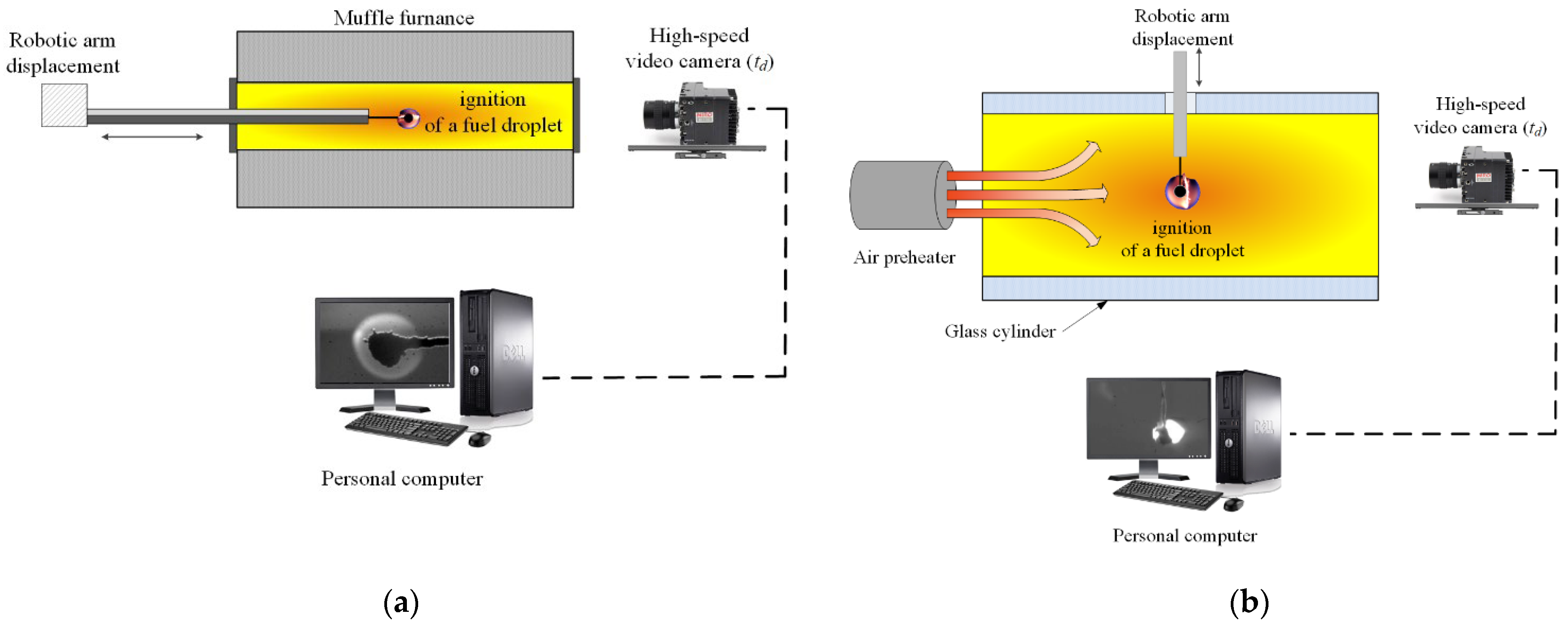
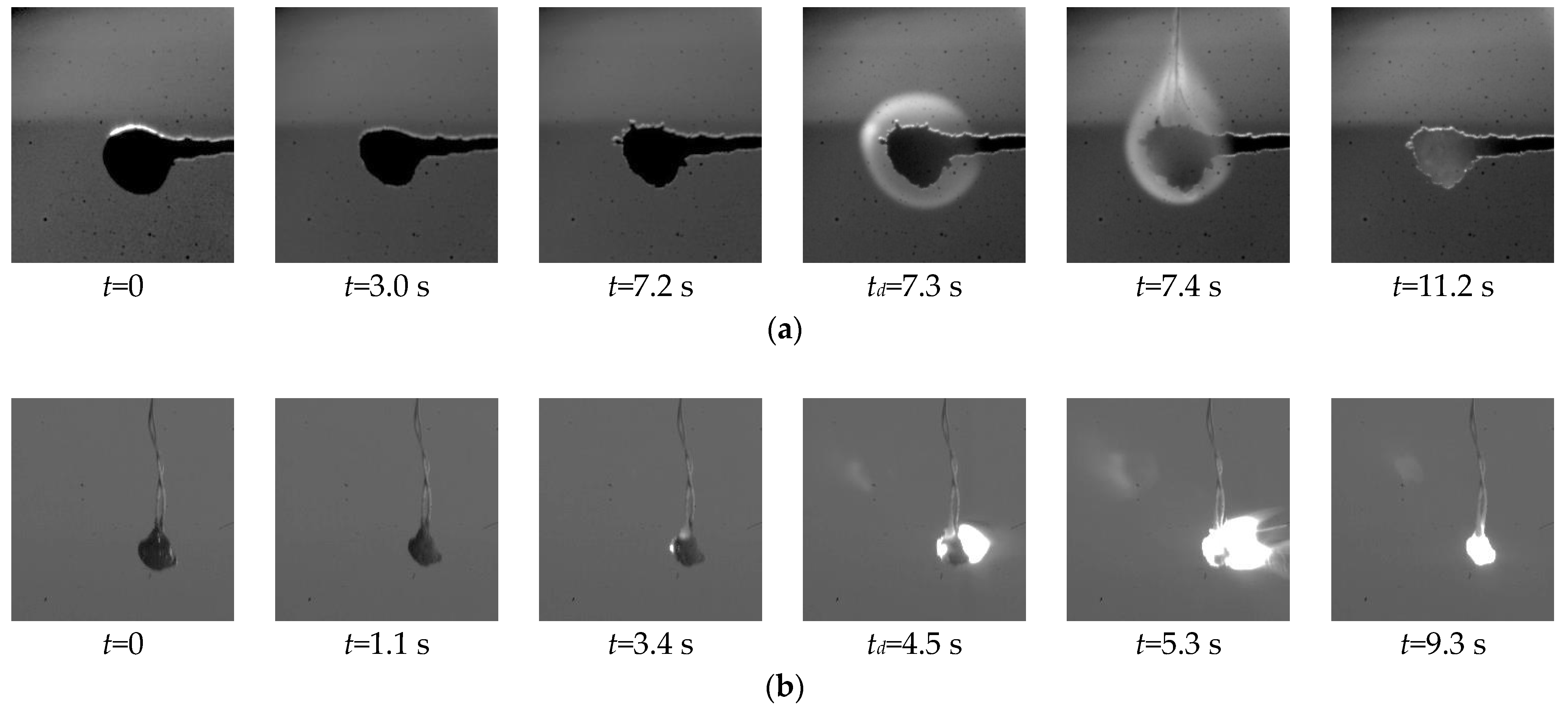
2.2. Experimental Data
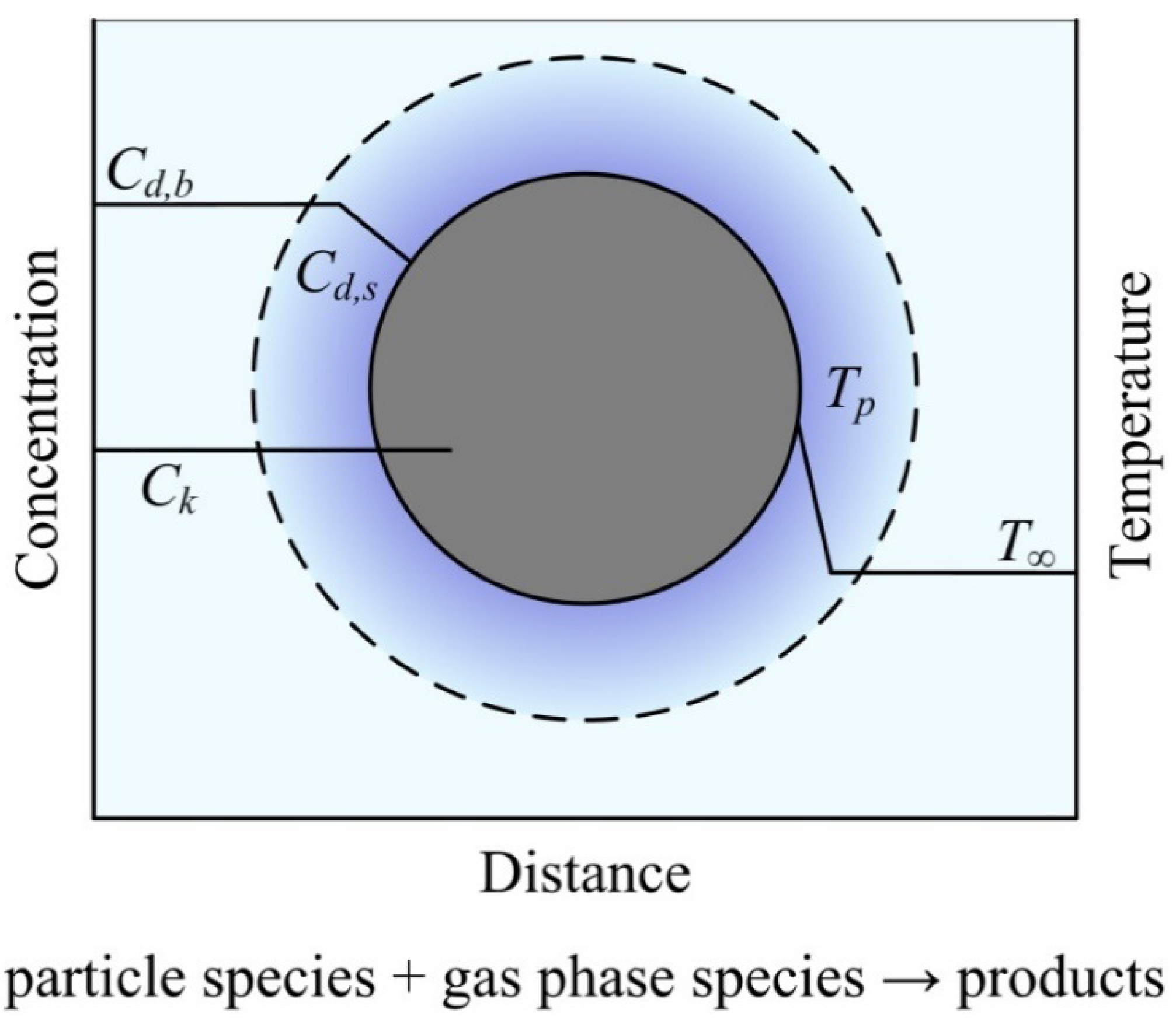
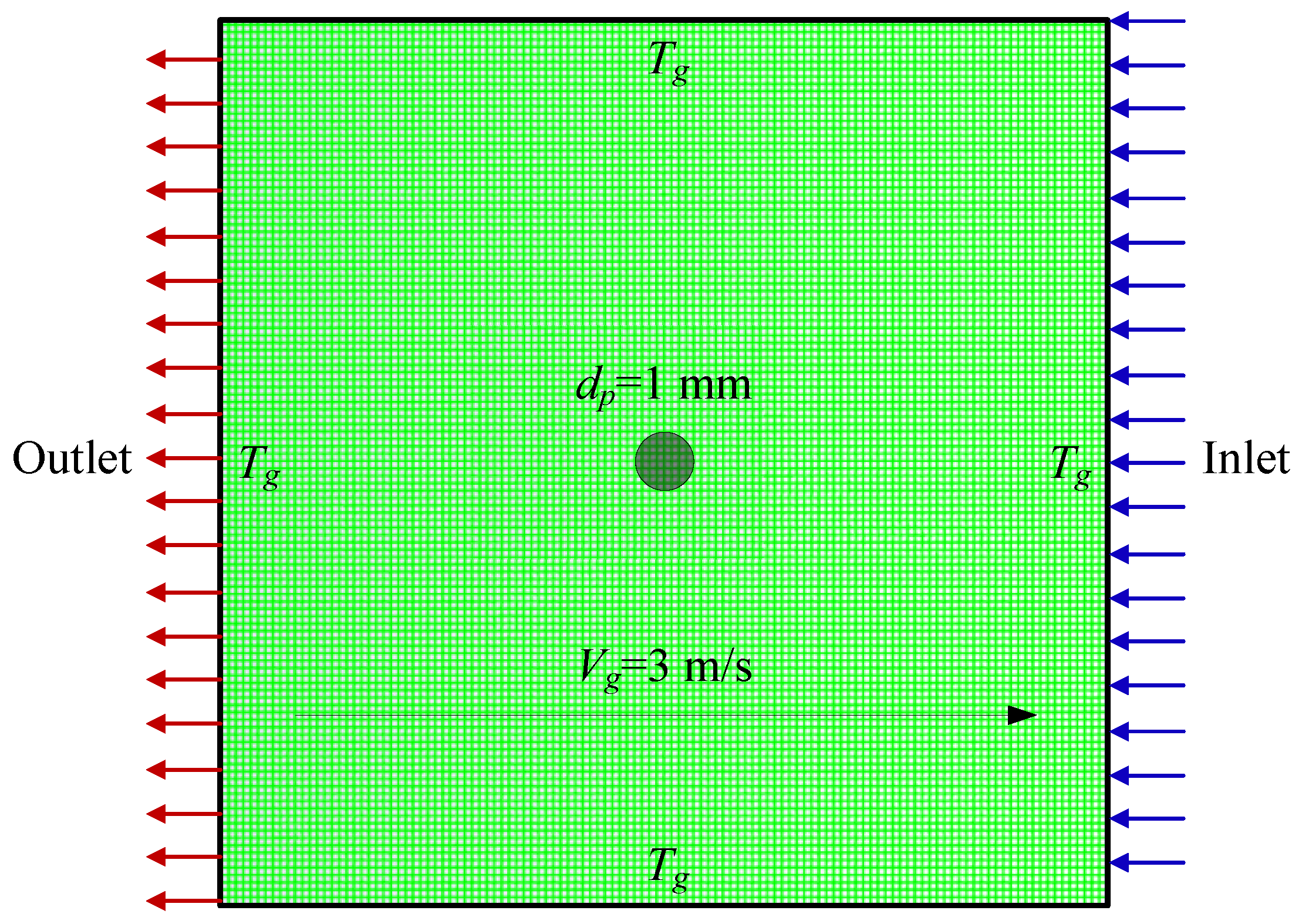
2.3. Mathematical Model
3. Results and Discussion
4. Effect of Temperature Gradient Inside the Droplet and in Its Vicinity
5. Conclusions
Author Contributions
Funding
Institutional Review Board Statement
Informed Consent Statement
Conflicts of Interest
Abbreviations
| CF | combustible fraction |
| CLF | composite liquid fuel |
| DC | devolatilization constant |
| DPM | discrete particle model |
| FC | filter cake |
| MSW | municipal solid waste |
| RANS | Reynolds-averaged Navier-Stokes equations |
| TPP | thermal power plant |
| VF | volatile fraction |
Nomenclature
| Ad | ash content, % |
| ap | thermal diffusivity of CLF, m2/s |
| Ap | surface area of the droplet, m2 |
| Ar | pre-exponential factor |
| A0 | rate constant, s−1 |
| CD | drag coefficient for spherical droplet |
| Cdaf, Hdaf, Ndaf, Odaf, Sdaf | fraction of carbon, hydrogen, nitrogen, oxygen, sulfur in the sample converted to a dry ash free state, % |
| Cd,b, Cd,s | concentration of the diffusion-limited species |
| Ci,s | vapor concentration at the droplet surface, kg·mol/m3 |
| Ci,∞ | vapor concentration in the bulk gas, kg·mol/m3 |
| Ck | concentrations of all other species |
| cp | particle (droplet) heat capacity, J/(kg·K) |
| cp,∞ | gas heat capacity, J/(kg∙K) |
| C1,r | molar concentration of species j in reactions, mol |
| Di,m | diffusion coefficient of vapor in the bulk, m2/s |
| dp | particle (droplet) diameter, m |
| D0,r | diffusion rate coefficient for reaction |
| Er | activation energy for reaction, J/(mol·K) |
| vector of volumetric fluid / particle interaction force, N | |
| Fa | additional acceleration, N/kg |
| FD | coefficient in drag law, 1/s |
| fh | particle fraction which absorbs heat of reaction |
| fv,0 | initial mass fraction of volatiles |
| fw,0 | initial mass fraction of evaporating material |
| gravity acceleration, m/s2 | |
| Gk | generation of turbulence kinetic energy related to the mean velocity gradient and the turbulent model constants |
| H | enthalpy, W |
| h | convective heat transfer coefficient, W/(m2·K) |
| hfg | latent heat, J/kg |
| hi | sensible heat, W |
| Hreac | heat released by the surface reaction, J/kg |
| mass flux, kg/(m2·s) | |
| k | turbulent kinetic energy, m2/s2 |
| kc | mass transfer coefficient, m/s |
| k∞ | thermal conductivity of the gas, W/(m∙K) |
| mp | particle (droplet) mass, kg |
| mp,0 | initial particle (droplet) mass, kg |
| Mw,i | molecular weight of species i, kg/mol·K |
| Ni | molar flux of vapor, kg·mol/(m2∙s) |
| Nr | apparent order of reaction |
| Nu | Nusselt number |
| p | gas local absolute pressure, Pa |
| pn | bulk partial pressure of the gas phase species, Pa |
| Pr | Prandtl number |
| pr,d | bulk partial pressure of the diffusion-limited species, Pa |
| psat | saturated vapor pressure, Pa |
| Q | heat of combustion, J/kg |
| Qas,V | higher heating value, J/kg |
| r | droplet radius in spherical coordinates, m |
| R | the universal gas constant, J/(K·mol) |
| Rp | rate of production, units vary |
| Re | relative Reynolds number |
| rate of particle surface species depletion, kg/s | |
| Rj,r | rate of particle surface species reaction per unit area, kg/(m2·s) |
| Rkin,r | kinetic rate of reaction, units vary |
| Sc | Schmidt number |
| Sh | Sherwood number |
| t | time, s |
| Tbp | boiling point, K |
| Td | CLF ignition temperature, K |
| td | ignition delay time, s |
| Tg | oxidizer temperature, K |
| tgf | gas-phase ignition-delay time, s |
| thg | heterogeneous ignition-delay time of CLF, s |
| Tp | droplet temperature, K |
| Tp,0 | initial particle (droplet) temperature, K |
| Tvap | vaporization temperature, K |
| T∞ | gas temperature, K |
| velocity vector, m/s | |
| u | gas velocity, m/s |
| up | particle velocity, m/s |
| Vdaf | volatile content, % |
| Vg | oxidizer velocity, m/s |
| Wa | moisture content, % |
| Xi | local bulk mole fraction of species i |
| Y | mass fraction of solid fuel |
| Yj | mass fraction of surface species j in the particle |
| Greek symbols | |
| βr | temperature exponent |
| Δr | step on spatial coordinate, m |
| Δt | time step, s |
| ε | turbulent dissipation rate, m2/s3 |
| εp | particle emissivity |
| ηr | effectiveness factor |
| θR | radiation temperature, K |
| µ | gas dynamic viscosity, Pa·s |
| µt | turbulent dynamic viscosity, Pa·s |
| ρ | gas density, kg/m3 |
| ρp | particle (droplet) density, kg/m3 |
| σ | Stefan-Boltzmann constant, W/(m2·K4) |
| σk | turbulent Prandtl number for turbulent kinetic energy |
| σε | turbulent Prandtl number for turbulent dissipation rate |
| gas viscous stress, Pa | |
| φO2 | mass content of oxygen in the air |
| Subscripts | |
| i | species |
| n | number of gas phase specie |
References
- Khan, H.H.; Malik, M.N.; Zafar, R.; Goni, F.A.; Chofreh, A.G.; Klemeš, J.J.; Alotaibi, Y. Challenges for Sustainable Smart City Development: A Conceptual Framework. Sustain. Dev. 2020, 28, 1507–1518. [Google Scholar] [CrossRef]
- IEA World Energy Outlook 2020. Available online: https://iea.blob.core.windows.net/assets/a72d8abf-de08-4385-8711-b8a062d6124a/WEO2020.pdf (accessed on 1 March 2021).
- Global Information Inc. Global Industrial Waste Management Market-2019–2026; Global Information Inc.: Tokyo, Japan, 2020. [Google Scholar]
- Gupta, A.; Paranjape, N. Industrial Solid Waste Management Market 2020–2026; Global Market Insights Inc.: Selbyville, DE, USA, 2020. [Google Scholar]
- Kaza, S.; Yao, L.C.; Bhada-Tata, P.; Van Woerden, F. What a Waste 2.0: A Global Snapshot of Solid Waste Management to 2050; World Bank: Washington, DC, USA, 2018; ISBN 978-1-4648-1329-0. [Google Scholar]
- Sabour, M.R.; Alam, E.; Hatami, A.M. Global Trends and Status in Landfilling Research: A Systematic Analysis. J. Mater. Cycles Waste Manag. 2020, 22, 711–723. [Google Scholar] [CrossRef]
- Chen, D.M.C.; Bodirsky, B.L.; Krueger, T.; Mishra, A.; Popp, A. The World’s Growing Municipal Solid Waste: Trends and Impacts. Environ. Res. Lett. 2020, 15, 074021. [Google Scholar] [CrossRef]
- Xin, C.; Zhang, T.; Tsai, S.-B.; Zhai, Y.-M.; Wang, J. An Empirical Study on Greenhouse Gas Emission Calculations under Different Municipal Solid Waste Management Strategies. Appl. Sci. 2020, 10, 1673. [Google Scholar] [CrossRef] [Green Version]
- Han, Z.; Wang, S.; Zhao, J.; Hu, X.; Fei, Y.; Xu, M. Identification of Nitrogen-Sources in an Aquifer beneath a Municipal Solid Waste Landfill in the Vicinity of Multiple Pollutant Sources. J. Environ. Manag. 2020, 268, 110661. [Google Scholar] [CrossRef] [PubMed]
- Foster, W.; Azimov, U.; Gauthier-Maradei, P.; Molano, L.C.; Combrinck, M.; Munoz, J.; Esteves, J.J.; Patino, L. Waste-to-Energy Conversion Technologies in the UK: Processes and Barriers–A Review. Renew. Sustain. Energy Rev. 2021, 135, 110226. [Google Scholar] [CrossRef]
- Glushkov, D.O.; Strizhak, P.A. Ignition of Composite Liquid Fuel Droplets Based on Coal and Oil Processing Waste by Heated Air Flow. J. Clean. Prod. 2017, 165, 1445–1461. [Google Scholar] [CrossRef]
- Staroń, A.; Kowalski, Z.; Staroń, P.; Banach, M. Studies on CWL with Glycerol for Combustion Process. Environ. Sci. Pollut. Res. 2019, 26, 2835–2844. [Google Scholar] [CrossRef] [PubMed] [Green Version]
- Zhao, Z.; Wang, R.; Ge, L.; Wu, J.; Yin, Q.; Wang, C. Energy Utilization of Coal-Coking Wastes via Coal Slurry Preparation: The Characteristics of Slurrying, Combustion, and Pollutant Emission. Energy 2019, 168, 609–618. [Google Scholar] [CrossRef]
- Aliukov, S.; Osintsev, K. Mathematical Modeling of Coal Dust Screening by Means of Sieve Analysis and Coal Dust Combustion Based on New Methods of Piece-linear Function Approximation. Appl. Sci. 2021, 11, 1609. [Google Scholar] [CrossRef]
- Sun, W.; Zhong, W.; Zhang, J.; Echekki, T. Large Eddy Simulation on the Effects of Coal Particles Size on Turbulent Combustion Characteristics and NOx Formation inside a Corner-Fired Furnace. J. Energy Resour. Technol. 2021, 143, 082302. [Google Scholar] [CrossRef]
- Gu, T.; Yin, C.; Ma, W.; Chen, G. Municipal Solid Waste Incineration in a Packed Bed: A Comprehensive Modeling Study with Experimental Validation. Appl. Energy 2019, 247, 127–139. [Google Scholar] [CrossRef]
- Janajreh, I.; Adeyemi, I.; Elagroudy, S. Gasification Feasibility of Polyethylene, Polypropylene, Polystyrene Waste and Their Mixture: Experimental Studies and Modeling. Sustain. Energy Technol. Assess. 2020, 39, 100684. [Google Scholar] [CrossRef]
- Bahari, A.; Atashkari, K.; Mahmoudimehr, J. Multi-Objective Optimization of a Municipal Solid Waste Gasifier. Biomass Convers. Biorefinery 2020, 11, 1703–1718. [Google Scholar] [CrossRef]
- Somwangthanaroj, S.; Fukuda, S. Investigation of Multi-Fuel Combustion Behavior and Synergy Effect Using Improved Steady-State Discrete Particle Model Simulation. Int. J. Energy Res. 2020, 45, 17291–17301. [Google Scholar] [CrossRef]
- Zhuo, Y.; Shen, Y. Three-Dimensional Transient Modelling of Coal and Coke Co-Combustion in the Dynamic Raceway of Ironmaking Blast Furnaces. Appl. Energy 2020, 261, 114456. [Google Scholar] [CrossRef]
- Tokmurzin, D.; Adair, D. Development of Euler-Lagrangian Simulation of a Circulating Fluidized Bed Reactor for Coal Gasification. Eurasian Chem. J. 2019, 21, 45–49. [Google Scholar] [CrossRef]
- Yang, R.; Ma, C.; Chen, G.; Cheng, Z.; Yan, B.; Mansour, M. Study on NOx Emission during Corn Straw/Sewage Sludge Co-Combustion: Experiments and Modelling. Fuel 2021, 285, 119208. [Google Scholar] [CrossRef]
- Glushkov, D.O.; Paushkina, K.K.; Shabardin, D.P.; Strizhak, P.A. Environmental Aspects of Converting Municipal Solid Waste into Energy as Part of Composite Fuels. J. Clean. Prod. 2018, 201, 1029–1042. [Google Scholar] [CrossRef]
- Glushkov, D.O.; Feoktistov, D.V.; Kuznetsov, G.V.; Batishcheva, K.A.; Kudelova, T.; Paushkina, K.K. Conditions and Characteristics of Droplets Breakup for Industrial Waste-Derived Fuel Suspensions Ignited in High-Temperature Air. Fuel 2020, 265, 116915. [Google Scholar] [CrossRef]
- Nyashina, G.S.; Legros, J.C.; Strizhak, P.A. Environmental Potential of Using Coal-Processing Waste as the Primary and Secondary Fuel for Energy Providers. Energies 2017, 10, 405. [Google Scholar] [CrossRef] [Green Version]
- Nyashina, G.S.; Kuznetsov, G.V.; Strizhak, P.A. Energy Efficiency and Environmental Aspects of the Combustion of Coal-Water Slurries with and without Petrochemicals. J. Clean. Prod. 2018, 172, 1730–1738. [Google Scholar] [CrossRef]
- Nyashina, G.S.; Kurgankina, M.A.; Strizhak, P.A. Environmental, Economic and Energetic Benefits of Using Coal and Oil Processing Waste Instead of Coal to Produce the Same Amount of Energy. Energy Convers. Manag. 2018, 174, 175–187. [Google Scholar] [CrossRef]
- Glushkov, D.O.; Paushkina, K.K.; Shabardin, D.P.; Strizhak, P.A.; Gutareva, N.Y. Municipal Solid Waste Recycling by Burning It as Part of Composite Fuel with Energy Generation. J. Environ. Manag. 2019, 231, 896–904. [Google Scholar] [CrossRef] [PubMed]
- Moriguchi, Y.; Hashimoto, S. Material Flow Analysis and Waste Management. In Taking Stock of Industrial Ecology; Springer International Publishing: Cham, Switzerland, 2016; pp. 247–262. ISBN 9783319205717. [Google Scholar]
- Edjabou, M.E.; Martín-Fernández, J.A.; Scheutz, C.; Astrup, T.F. Statistical Analysis of Solid Waste Composition Data: Arithmetic Mean, Standard Deviation and Correlation Coefficients. Waste Manag. 2017, 69, 13–23. [Google Scholar] [CrossRef] [PubMed] [Green Version]
- Faitli, J.; Magyar, T.; Erdélyi, A.; Murányi, A. Characterization of Thermal Properties of Municipal Solid Waste Landfills. Waste Manag. 2015, 36, 213–221. [Google Scholar] [CrossRef] [PubMed]
- Birgen, C.; Magnanelli, E.; Carlsson, P.; Skreiberg, Ø.; Mosby, J.; Becidan, M. Machine Learning Based Modelling for Lower Heating Value Prediction of Municipal Solid Waste. Fuel 2021, 283, 118906. [Google Scholar] [CrossRef]
- Wang, D.; Tang, Y.T.; He, J.; Yang, F.; Robinson, D. Generalized Models to Predict the Lower Heating Value (LHV) of Municipal Solid Waste (MSW). Energy 2021, 216, 119279. [Google Scholar] [CrossRef]
- Tabakaev, R.; Shanenkov, I.; Kazakov, A.; Zavorin, A. Thermal Processing of Biomass into High-Calorific Solid Composite Fuel. J. Anal. Appl. Pyrolysis 2017, 124, 94–102. [Google Scholar] [CrossRef]
- Ilinykh, G.V. Evaluation of Thermotechnical Properties of Solid Waste from Their Morphological Composition. Vestn. Permsk. Natsionalnogo Issledovatelskogo Politekh. Univ. Urban. 2013, 11, 125–137. [Google Scholar]
- Glushkov, D.O.; Strizhak, P.A.; Chernetskii, M.Y. Organic Coal-Water Fuel: Problems and Advances (Review). Therm. Eng. 2016, 63, 707–717. [Google Scholar] [CrossRef]
- Glushkov, D.O.; Shabardin, D.P.; Strizhak, P.A.; Vershinina, K.Y. Influence of Organic Coal-Water Fuel Composition on the Characteristics of Sustainable Droplet Ignition. Fuel Process. Technol. 2016, 143, 60–68. [Google Scholar] [CrossRef]
- Dmitrienko, M.A.; Strizhak, P.A.; Tsygankova, Y.S. Technoeconomic Analysis of Prospects of Use of Organic Coal-Water Fuels of Various Component Compositions. Chem. Pet. Eng. 2017, 53, 195–202. [Google Scholar] [CrossRef]
- Stöllinger, M.; Naud, B.; Roekaerts, D.; Beishuizen, N.; Heinz, S. PDF Modeling and Simulations of Pulverized Coal Combustion-Part 1: Theory and Modeling. Combust. Flame 2013, 160, 384–395. [Google Scholar] [CrossRef]
- Lyulin, Y.V.; Feoktistov, D.V.; Afanas’ev, I.A.; Chachilo, E.S.; Kabov, O.A.; Kuznetsov, G.V. Measuring the Rate of Local Evaporation from the Liquid Surface under the Action of Gas Flow. Tech. Phys. Lett. 2015, 41, 665–667. [Google Scholar] [CrossRef]
- Glushkov, D.O.; Paushkina, K.K.; Shabardin, D.P. Co-Combustion of Coal Processing Waste, Oil Refining Waste and Municipal Solid Waste: Mechanism, Characteristics, Emissions. Chemosphere 2020, 240, 124892. [Google Scholar] [CrossRef]
- ANSYS Academic Research ANSYS Fluent Theory Guide. In ANSYS Help System; ANSYS, Inc.: Canonsburg, PA, USA, 2018.
- Ranz, W.E.; Marshall, W.R. Evaporation From Drops–Part I. Chem. Eng. Prog. 1952, 48, 141–146. [Google Scholar]
- Aissa, A.; Abdelouahab, M.; Noureddine, A.; Elganaoui, M.; Pateyron, B. Ranz and Marshall Correlations Limits on Heat Flow between a Sphere and Its Surrounding Gas at High Temperature. Therm. Sci. 2015, 19, 1521–1528. [Google Scholar] [CrossRef]
- Baum, M.M.; Street, P.J. Predicting the Combustion Behaviour of Coal Particles. Combust. Sci. Technol. 1971, 3, 231–243. [Google Scholar] [CrossRef]
- Wijayanta, A.T.; Alam, M.S.; Nakaso, K.; Fukai, J.; Kunitomo, K.; Shimizu, M. Combustibility of Biochar Injected into the Raceway of a Blast Furnace. Fuel Process. Technol. 2014, 117, 53–59. [Google Scholar] [CrossRef]
- Ejeh, C.; Afgan, I.; AlMansob, H.; Brantson, E.; Fekala, J.; Odiator, M.; Stanley, P.; Anumah, P.; Onyekperem, C.; Boah, E. Computational Fluid Dynamics for Ameliorating Oil Recovery Using Silicon-Based Nanofluids and Ethanol in Oil-Wet Reservoirs. Energy Rep. 2020, 6, 3023–3035. [Google Scholar] [CrossRef]
- Glushkov, D.O.; Kuznetsov, G.V.; Paushkina, K.K.; Shabardin, D.P. The Main Elements of a Strategy for Combined Utilization of Industrial and Municipal Waste from Neighboring Regions by Burning It as Part of Composite Fuels. Energies 2018, 11, 2534. [Google Scholar] [CrossRef]
- Taghiyeva, S.F.; Jafarov, R.P.; Kasimov, A.A.; Qadji-Kasumov, V.S.; Rustamov, M.I. Kinetic Model of Hydrogenation of Carbon Dioxide on the Catalyst Fe, Ni/γ-Al2O3. PPOR 2017, 18, 62–68. [Google Scholar]
- Wickramaarachchi, W.A.M.K.P.; Narayana, M. Pyrolysis of Single Biomass Particle Using Three-Dimensional Computational Fluid Dynamics Modelling. Renew. Energy 2020, 146, 1153–1165. [Google Scholar] [CrossRef]
- Wei, X.; Zhong, H.; Yang, Q.; Yao, E.; Zhang, Y.; Zou, H. Studying the Mechanisms of Natural Rubber Pyrolysis Gas Generation Using RMD Simulations and TG-FTIR Experiments. Energy Convers. Manag. 2019, 189, 143–152. [Google Scholar] [CrossRef]
- Vatani, A.; Mehrpooya, M.; Gharagheizi, F. Prediction of Standard Enthalpy of Formation by a QSPR Model. Int. J. Mol. Sci. 2007, 8, 407–432. [Google Scholar] [CrossRef] [Green Version]
- Parks, G.S.; Mosher, H.P. Enthalpy and Free Energy Changes in Some Simple Polymerization Processes. J. Polym. Sci. Part A Gen. Pap. 1963, 1, 1979–1984. [Google Scholar] [CrossRef]
- Salomatov, V.V.; Kuznetsov, G.V.; Syrodoy, S.V. Influence of the Degree of Coal Metamorphism on Characteristics and Conditions of Ignition of Coal-Water Fuel Drops. Thermophys. Aeromechanics 2018, 25, 773–788. [Google Scholar] [CrossRef]
- Arena, U. Process and Technological Aspects of Municipal Solid Waste Gasification. A Review. Waste Manag. 2012, 32, 625–639. [Google Scholar] [CrossRef] [PubMed]
- Guan, Y.; Luo, S.; Liu, S.; Xiao, B.; Cai, L. Steam Catalytic Gasification of Municipal Solid Waste for Producing Tar-Free Fuel Gas. Int. J. Hydrogen Energy 2009, 34, 9341–9346. [Google Scholar] [CrossRef]
- Donskoy, I.G. Numerical Study on the Efficiency of Biomass and Municipal Waste Fixed-Bed Co-Gasification. E3S Web Conf. 2019, 114, 06006. [Google Scholar] [CrossRef]
- Xie, J.; Zhong, W.; Jin, B.; Shao, Y.; Huang, Y. Eulerian–Lagrangian Method for Three-Dimensional Simulation of Fluidized Bed Coal Gasification. Adv. Powder Technol. 2013, 24, 382–392. [Google Scholar] [CrossRef]
- Chen, C.J.; Hung, C.I.; Chen, W.H. Numerical Investigation on Performance of Coal Gasification under Various Injection Patterns in an Entrained Flow Gasifier. Appl. Energy 2012, 100, 218–228. [Google Scholar] [CrossRef]
- He, C.; Feng, X.; Chu, K.H.; Li, A.; Liu, Y. Industrial-Scale Fixed-Bed Coal Gasification: Modeling, Simulation and Thermodynamic Analysis. Chinese J. Chem. Eng. 2014, 22, 522–530. [Google Scholar] [CrossRef]
- Haseli, Y.; van Oijen, J.A.; de Goey, L.P.H. A Detailed One-Dimensional Model of Combustion of a Woody Biomass Particle. Bioresour. Technol. 2011, 102, 9772–9782. [Google Scholar] [CrossRef] [PubMed]
- Zhang, Q.; Dor, L.; Fenigshtein, D.; Yang, W.; Blasiak, W. Gasification of Municipal Solid Waste in the Plasma Gasification Melting Process. Appl. Energy 2012, 90, 106–112. [Google Scholar] [CrossRef]
- Uskov, S.I.; Enikeeva, L.V.; Potemkin, D.I.; Belyaev, V.D.; Snytnikov, P.V.; Gubaidullin, I.M.; Kirillov, V.A.; Sobyanin, V.A. Kinetics of Low-Temperature Steam Reforming of Propane in a Methane Excess on a Ni-Based Catalyst. Catal. Ind. 2017, 9, 104–109. [Google Scholar] [CrossRef]
- McAllister, S.; Chen, J.-Y.; Fernandez-Pello, A.C. Chemical Kinetics. In Fundamentals of Combustion Processes; Springer: New York, NY, USA, 2011; pp. 49–73. [Google Scholar]
- Matthess, N.; Schweich, D.; Martin, B.; Castagna, F. From Light-off Curves to Kinetic Rate Expressions for Three-Way Catalysts. Top. Catal. 2001, 16–17, 119–124. [Google Scholar] [CrossRef]
- Westbrook, C.K.; Dryer, F.L. Chemical Kinetic Modeling of Hydrocarbon Combustion. Prog. Energy Combust. Sci. 1984, 10, 1–57. [Google Scholar] [CrossRef]
- Mendoza, J.A.; Hwang, S. Tubular Reactor Design for the Oxidative Dehydrogenation of Butene Using Computational Fluid Dynamics (CFD) Modeling. Korean J. Chem. Eng. 2018, 35, 2157–2163. [Google Scholar] [CrossRef]
- Cheng, G.; Farmer, R.; Jones, H.; McFarlane, J. Numerical Simulation of the Internal Ballistics of a Hybrid Rocket Motor. In Proceedings of the 32nd Aerospace Sciences Meeting and Exhibit, Reno, NV, USA, 10–13 January 1994; American Institute of Aeronautics and Astronautics: Reston, VA, USA, 1994. [Google Scholar]
- Tao, F.; Srinivas, S.; Reitz, R.D.; Foster, D.E. Comparison of Three Soot Models Applied to Multi-Dimensional Diesel Combustion Simulations. JSME Int. J. Ser. B 2005, 48, 671–678. [Google Scholar] [CrossRef] [Green Version]
- McAllister, S.; Chen, J.-Y.; Fernandez-Pello, A.C. Droplet Evaporation and Combustion. In Fundamentals of Combustion Processes; Springer: New York, NY, USA, 2011; pp. 155–175. [Google Scholar]
- Celik, I.B.; Ghia, U.; Roache, P.J.; Freitas, C.J.; Coleman, H.; Raad, P.E. Procedure for Estimation and Reporting of Uncertainty Due to Discretization in CFD Applications. J. Fluids Eng. Trans. ASME 2008, 130, 0780011–0780014. [Google Scholar] [CrossRef]
- Fugmann, H.; Schnabel, L.; Frohnapfel, B. Heat Transfer and Pressure Drop Correlations for Laminar Flow in an In-Line and Staggered Array of Circular Cylinders. Numer. Heat Transf. Part A Appl. 2019, 75, 1–20. [Google Scholar] [CrossRef]
- Glushkov, D.O.; Strizhak, P.A.; Vershinina, K.Y. Minimum Temperatures for Sustainable Ignition of Coal Water Slurry Containing Petrochemicals. Appl. Therm. Eng. 2016, 96, 534–546. [Google Scholar] [CrossRef]


| Component | Wa (%) | Ad (%) | Vdaf (%) | Qas,V (MJ/kg) | Specific Heat Capacity (kJ/(kg∙K)) | Thermal Conductivity (W/(m∙K)) |
|---|---|---|---|---|---|---|
| Filter cake C (dry) | - | 26.50 | 23.10 | 24.83 | 1.30 | 0.366 |
| Wood | 20.00 | 2.00 | 83.10 | 16.45 | 1.55 | 0.200 |
| Rubber | 2.00 | 1.80 | 67.40 | 33.50 | 1.38 | 0.150 |
| Plastic | 2.00 | 0.20 | 99.50 | 22.00 | 2.30 | 0.260 |
| Cardboard | 5.00 | 3.00 | 96.57 | 17.50 | 2.30 | 0.130 |
| Component | Cdaf (%) | Hdaf (%) | Ndaf (%) | Sdaf (%) | Odaf (%) |
|---|---|---|---|---|---|
| Filter cake C (dry) | 87.20 | 5.10 | 2.10 | 1.10 | 4.50 |
| Wood | 50.30 | 6.00 | 0.20 | 0.10 | 43.40 |
| Rubber | 97.90 | 1.20 | 0.30 | 0.60 | - |
| Plastic | 66.70 | 7.90 | - | - | 25.40 |
| Cardboard | 46.30 | 6.30 | 0.30 | 0.20 | 46.90 |
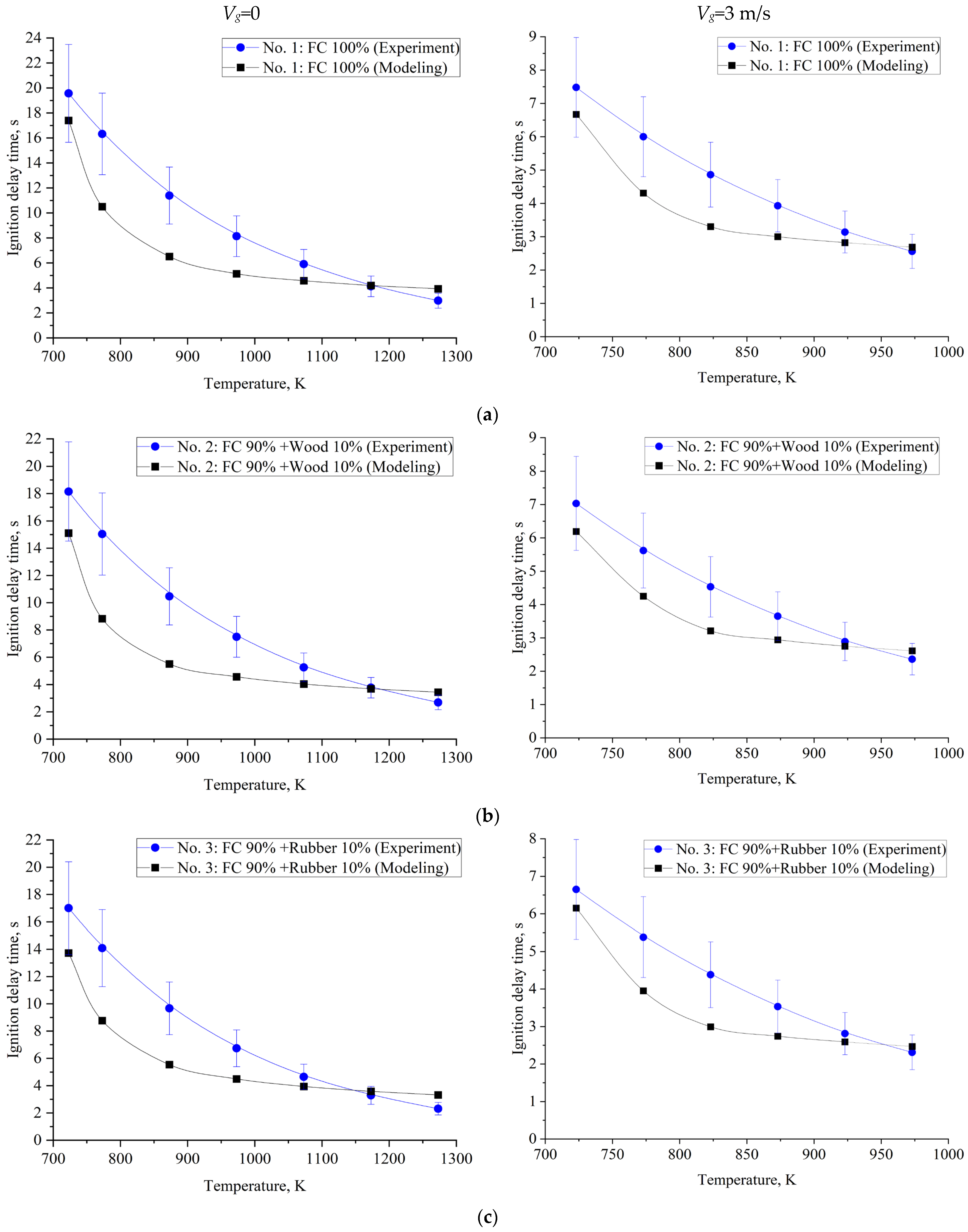
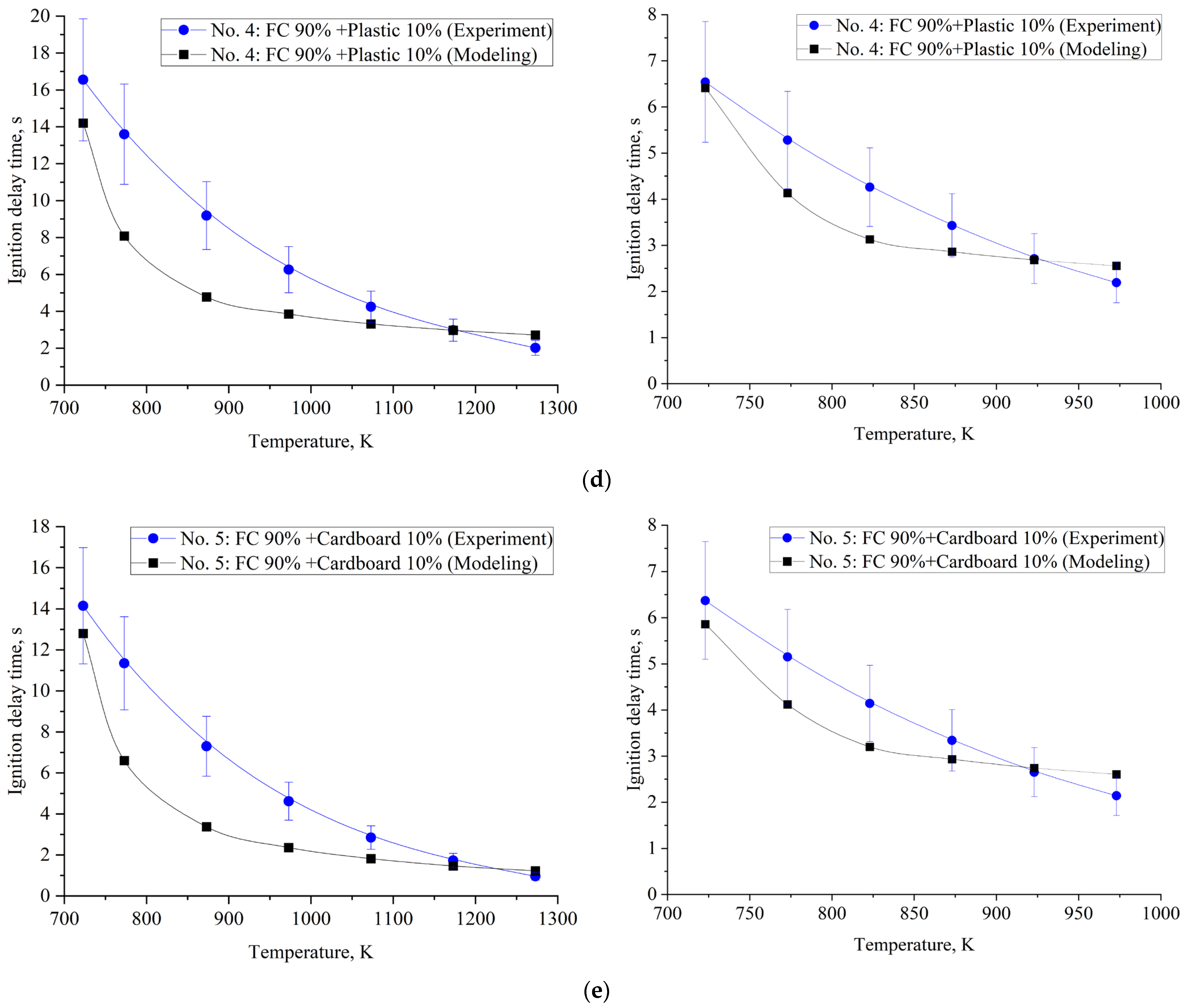
| No. of Composition | Temperature of Motionless Air (Vg ≈ 0) | ||||||
|---|---|---|---|---|---|---|---|
| 723 K | 773 K | 873 K | 973 K | 1073 K | 1173 K | 1273 K | |
| No. 1 | 19.57 | 16.32 | 11.39 | 8.14 | 5.90 | 4.13 | 2.98 |
| No. 2 | 18.15 | 15.04 | 10.47 | 7.50 | 5.26 | 3.77 | 2.69 |
| No. 3 | 17.00 | 14.08 | 9.67 | 6.74 | 4.65 | 3.29 | 2.31 |
| No. 4 | 16.55 | 13.60 | 9.19 | 6.26 | 4.25 | 2.98 | 2.02 |
| No. 5 | 14.15 | 11.35 | 7.30 | 4.62 | 2.85 | 1.73 | 0.96 |
| No. of Composition | Air-Flow Temperature (Vg ≈ 3 m/s) | |||||
|---|---|---|---|---|---|---|
| 723 K | 773 K | 823 K | 873 K | 923 K | 973 K | |
| No. 1 | 7.48 | 6.00 | 4.86 | 3.93 | 3.14 | 2.56 |
| No. 2 | 7.03 | 5.62 | 4.53 | 3.65 | 2.89 | 2.36 |
| No. 3 | 6.65 | 5.38 | 4.38 | 3.53 | 2.81 | 2.31 |
| No. 4 | 6.54 | 5.28 | 4.26 | 3.43 | 2.71 | 2.19 |
| No. 5 | 6.37 | 5.15 | 4.14 | 3.34 | 2.65 | 2.14 |
| Reaction | Ar | Er (kJ/(mol·K)) | Ref. |
|---|---|---|---|
| Water Evaporation | |||
| H2O(l) = H2O(g) | 5.13∙106 | 87.9 | [49,50] |
| Pyrolysis | |||
| Biomass pyrolysis | |||
| lignin = 0.209CO2 + 0.396CO + 0.109H2 + 0.249H2O + 0.037vol | 2.202∙1012 | 181 | [50] |
| hemicellulose = 0.209CO2 + 0.396CO+0.109H2 + 0.249H2O + 0.037vol | 2.527∙1011 | 147 | [50] |
| cellulose = 0.209CO2 + 0.396CO + 0.109H2 + 0.249H2O + 0.037vol | 1.379∙1014 | 193 | [50] |
| Rubber pyrolysis | |||
| rubber = 0.8H2 + 0.0009C2H4 + 0.194CH4 + 0.0025C3H6 + 0.0018C4H6 + 0.0008C2H2 | 5.5∙1018 | 181 | [51,52] |
| Plastic pyrolysis | |||
| polyethylene = 0.825H2 + 0.07C2H4 + 0.05CH4 + 0.03C3H6 + 0.02C2H6 + 0.005C3H8 | 15∙103 | 40 | [53] |
| Gasification | |||
| C + H2O = CO + H2 | 2.07∙107 | 220 | [50,54,55,56] |
| C + CO2 = 2CO | 1.32∙107 | 259 | [50,55,56,57,58,59] |
| C + 2H2 = CH4 | 5∙106 | 30 | [50,55,56,58] |
| C + 2H2O = CO2 + 2H2 | 2.1∙106 | 158 | [50,57,60] |
| CO2 + H2 = CO + H2O | 5∙106 | 30 | [49,58,61] |
| Combustion | |||
| C + O2 = CO2 | 2∙1012 | 60.6 | [55,57,62] |
| C + 1/2O2 = CO | 2∙1012 | 60.6 | [55,57,58,59] |
| H2 + 1/2O2 = H2O | 2.1∙1014 | 129.8 | [54,55,58] |
| 2CO + O2 = 2CO2 | 1.4∙1013 | 96.8 | [54,55,58] |
| CO + H2O = H2 + CO2 | 5∙106 | 30 | [55,56,58] |
| CO + 3H2 = CH4 + H2O | 5∙106 | 30 | [49] |
| C + H2O = 1/2CO2 + 1/2CH4 | 5.6∙1012 | 36.2 | [49,63] |
| CH4 + 2O2 = CO2 + 2H2O | 5.6∙1012 | 103.8 | [58,64] |
| C2H4 + O2 = 2CO + 2H2 | 1∙1012 | 173 | [21] |
| 2C3H6 + 9O2 = 6CO2 + 6H2O | 1.51∙1015 | 85.6 | [65] |
| 2C2H6 + 7O2 = 4CO2 + 6H2O | 1.1∙1012 | 125.52 | [66] |
| 2C3H8 + 10O2 = 6CO2 + 8H2O | 8.6∙1011 | 125.52 | [66] |
| C4H6 + 3O2 = 4CO + 2H2O + H2 | 8.8∙1011 | 126.37 | [67,68] |
| C4H8 + 1/2O2 = C2H4 + H2O | 6∙1012 | 502 | [67] |
| C4H8 + 6O2 = 4CO2 + 4H2O | 3∙107 | 10.4 | [67] |
| C4H6 + 11/2O2 = 4CO2 + 3H2O | 3∙107 | 10.4 | [67] |
| C2H2 + O2 = 2CO + H2 | 6∙1013 | 50 | [69] |
| Characteristics | No. of Composition | ||||
|---|---|---|---|---|---|
| No. 1 | No. 2 | No. 3 | No. 4 | No. 5 | |
| Q (MJ/kg) | 10.78 | 11.29 | 13.05 | 11.88 | 11.43 |
| Specific heat capacity (kJ/(kg∙K)) | 2.4600 | 2.4175 | 2.3549 | 2.4136 | 2.4136 |
| Thermal conductivity (W/(m∙K)) | 0.4796 | 0.4582 | 0.4550 | 0.4620 | 0.4547 |
| Viscosity (Pa∙s) | 0.557 | 0.557 | 0.557 | 0.557 | 0.557 |
| Wa (%) | 40.00 | 38.00 | 36.20 | 36.20 | 36.50 |
| Ad (%) | 26.50 | 24.05 | 24.03 | 23.87 | 24.15 |
| Vdaf (%) | 23.10 | 29.10 | 27.53 | 30.74 | 30.45 |
| Cdaf (%) | 87.20 | 83.51 | 88.27 | 85.15 | 83.11 |
| Hdaf (%) | 5.10 | 5.19 | 4.71 | 5.38 | 5.22 |
| Ndaf (%) | 2.10 | 1.91 | 1.92 | 1.89 | 1.92 |
| Sdaf (%) | 1.10 | 1.00 | 1.05 | 0.99 | 1.01 |
| Odaf (%) | 4.50 | 8.39 | 4.05 | 6.59 | 8.74 |
| Parameters | Grid 1 | Grid 2 (Examined) | Grid 3 |
|---|---|---|---|
| Number of cells | 5625 | 14,400 | 360,000 |
| Element size | 4·10−4 | 2.5·10−4 | 0.5·10−4 |
| Ignition-delay time of composite fuel No. 5 (at 1173 K, Vg = 0), s | 1.995 | 1.990 | 1.931 |
| GCI (%) | 0.062 | 0.036 | 0.001 |
Publisher’s Note: MDPI stays neutral with regard to jurisdictional claims in published maps and institutional affiliations. |
© 2022 by the authors. Licensee MDPI, Basel, Switzerland. This article is an open access article distributed under the terms and conditions of the Creative Commons Attribution (CC BY) license (https://creativecommons.org/licenses/by/4.0/).
Share and Cite
Antonov, D.; Glushkov, D.; Paushkina, K.; Kuznechenkova, D.; Ramanathan, A. A Mathematical Model of Industrial Waste-Derived Fuel Droplet Combustion in High-Temperature Air. Appl. Sci. 2022, 12, 12273. https://doi.org/10.3390/app122312273
Antonov D, Glushkov D, Paushkina K, Kuznechenkova D, Ramanathan A. A Mathematical Model of Industrial Waste-Derived Fuel Droplet Combustion in High-Temperature Air. Applied Sciences. 2022; 12(23):12273. https://doi.org/10.3390/app122312273
Chicago/Turabian StyleAntonov, Dmitrii, Dmitrii Glushkov, Kristina Paushkina, Daria Kuznechenkova, and Anand Ramanathan. 2022. "A Mathematical Model of Industrial Waste-Derived Fuel Droplet Combustion in High-Temperature Air" Applied Sciences 12, no. 23: 12273. https://doi.org/10.3390/app122312273