
Enhanced Proton Acceleration from Laser Interaction with a Tailored Nanowire Target


Abstract
:1. Introduction
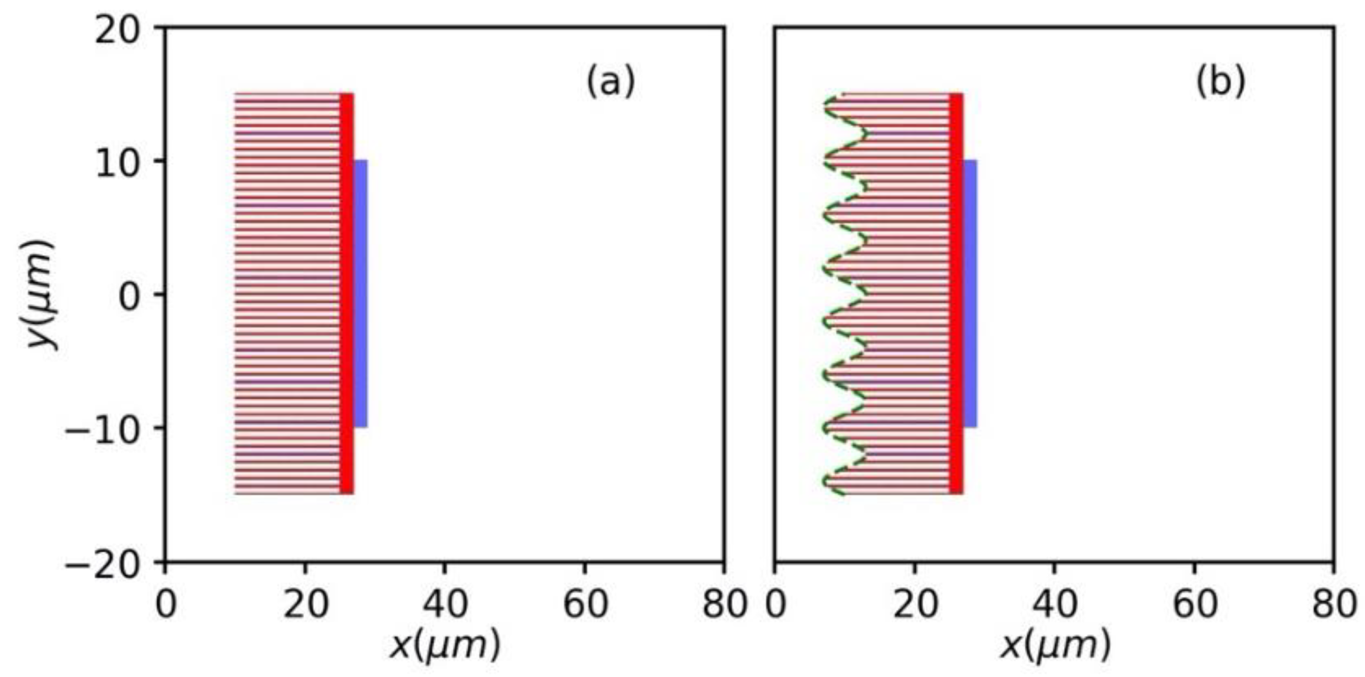
2. Simulation Setup
3. Results and Discussions
3.1. Laser Absorption and Hot Electron Generation
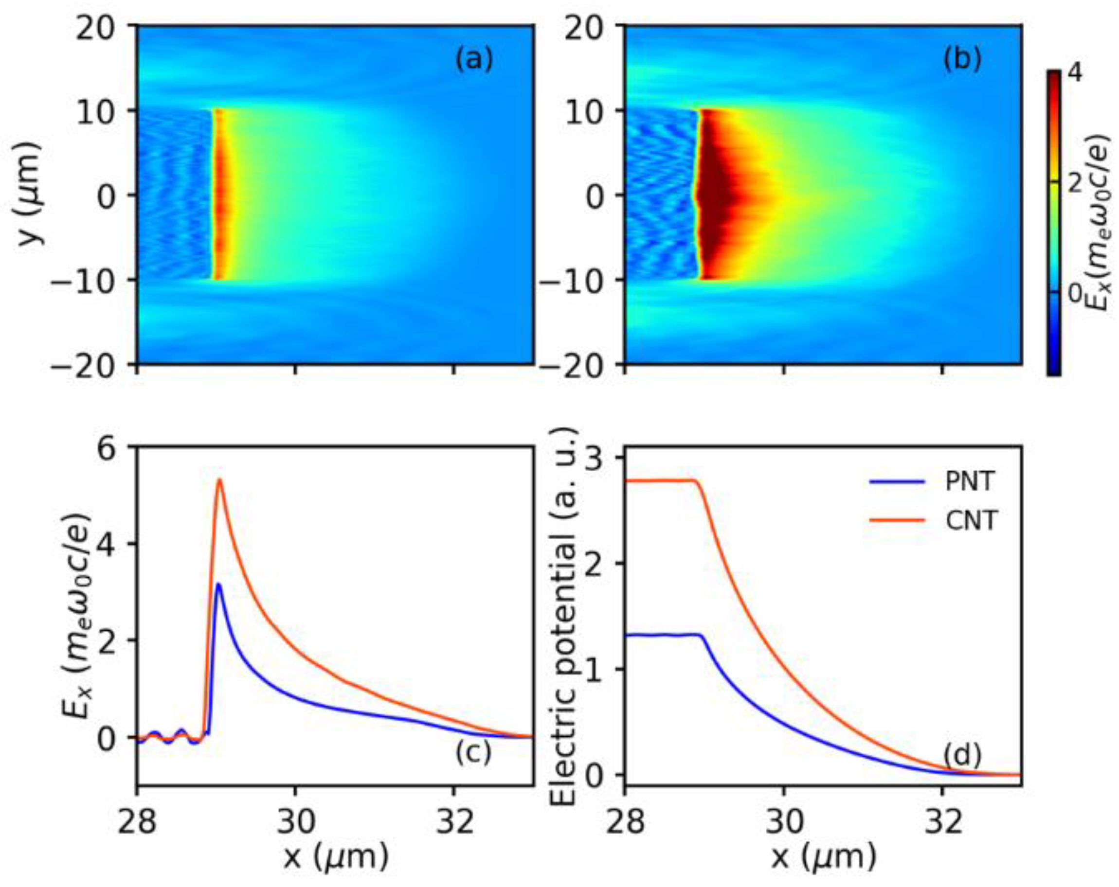
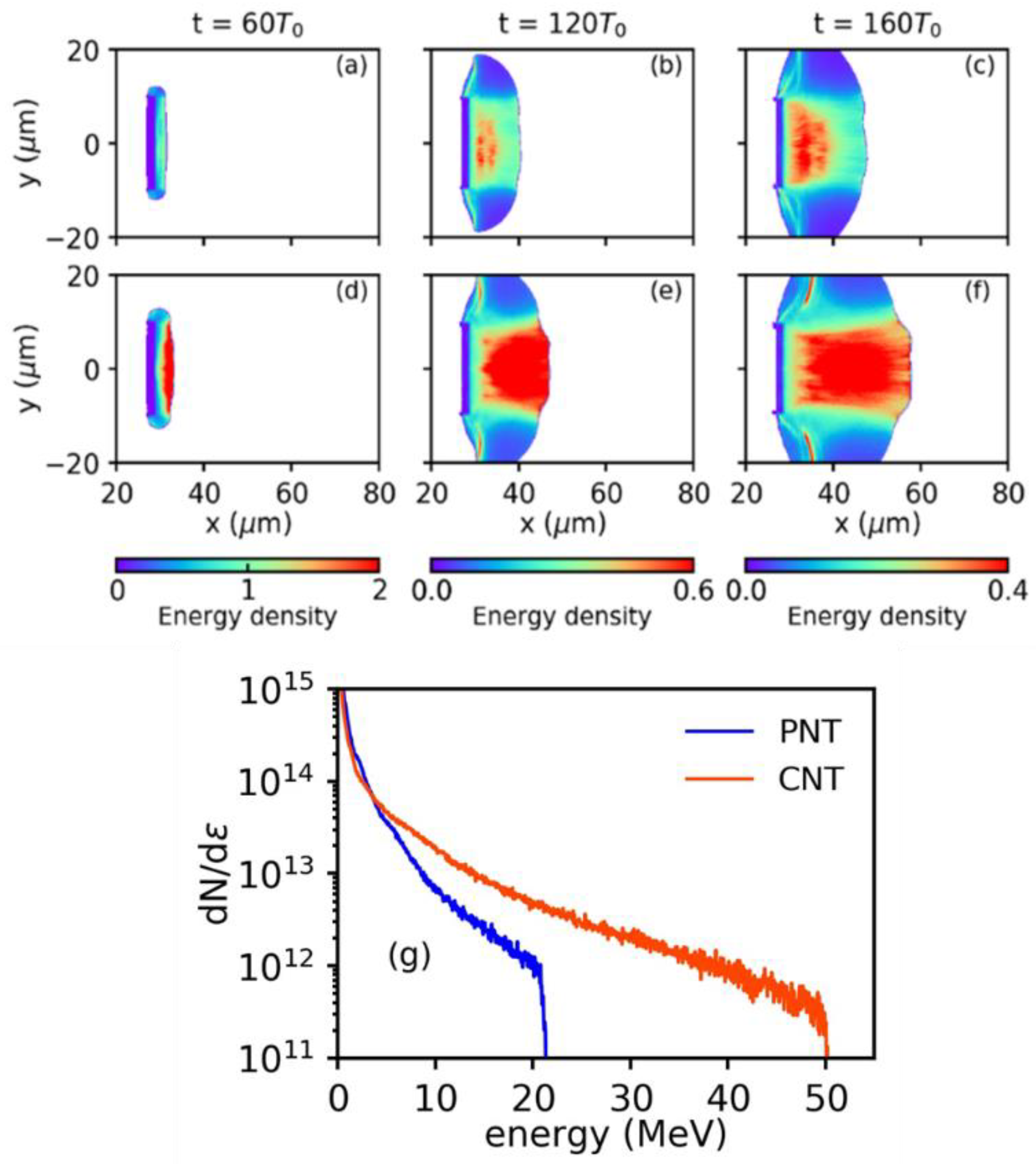
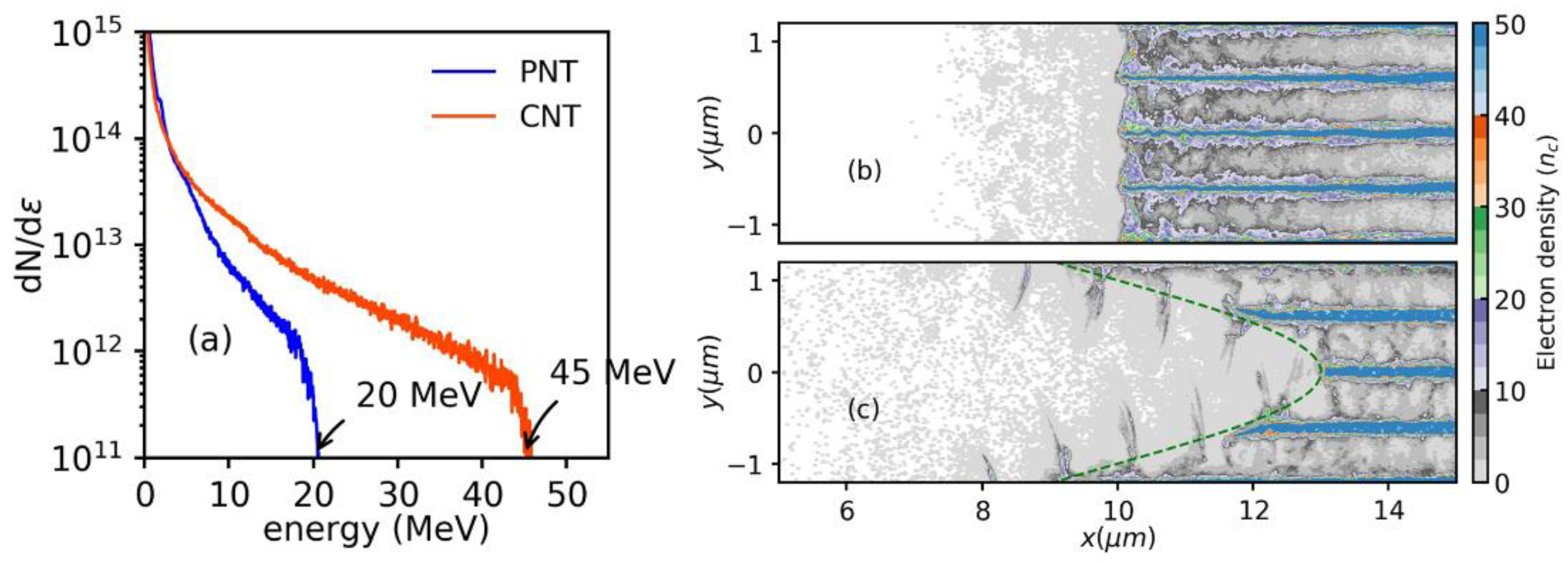
3.2. Sheath Filed and Proton Acceleration
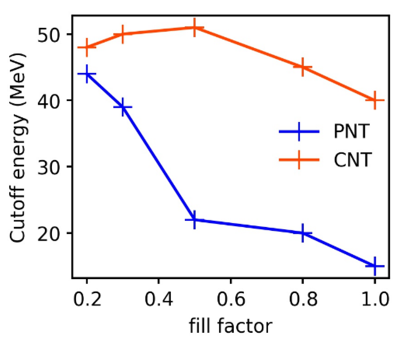
3.3. Robustness of the CNT
4. Conclusions
Author Contributions
Funding
Institutional Review Board Statement
Informed Consent Statement
Data Availability Statement
Acknowledgments
Conflicts of Interest
References
- Daido, H.; Nishiuchi, M.; Pirozhkov, A.S. Review of Laser-Driven Ion Sources and Their Applications. Rep. Prog. Phys. 2012, 75, 056401. [Google Scholar] [CrossRef]
- Borghesi, M.; Mackinnon, A.J.; Campbell, D.H.; Hicks, D.G.; Kar, S.; Patel, P.K.; Price, D.; Romagnani, L.; Schiavi, A.; Willi, O. Multi-MeV Proton Source Investigations in Ultraintense Laser-Foil Interactions. Phys. Rev. Lett. 2004, 92, 055003. [Google Scholar] [CrossRef]
- Schardt, D. Tumor Therapy with High-Energy Carbon Ion Beams. Nucl. Phys. A 2007, 787, 633–641. [Google Scholar] [CrossRef]
- Patel, P.; Mackinnon, A.; Key, M.; Cowan, T.; Foord, M.; Allen, M.; Price, D.; Ruhl, H.; Springer, P.; Stephens, R. Isochoric Heating of Solid-Density Matter with an Ultrafast Proton Beam. Phys. Rev. Lett. 2003, 91, 125004. [Google Scholar] [CrossRef] [Green Version]
- Palaniyappan, S.; Huang, C.; Gautier, D.C.; Hamilton, C.E.; Santiago, M.A.; Kreuzer, C.; Sefkow, A.B.; Shah, R.C.; Fernández, J.C. Efficient Quasi-Monoenergetic Ion Beams from Laser-Driven Relativistic Plasmas. Nat. Commun. 2015, 6, 10170. [Google Scholar] [CrossRef] [PubMed] [Green Version]
- Zhang, F.; Cai, H.B.; Zhou, W.M.; Dai, Z.S.; Shan, L.Q.; Xu, H.; Chen, J.B.; Ge, F.J.; Tang, Q.; Zhang, W.S.; et al. Enhanced Energy Coupling for Indirect-Drive Fast-Ignition Fusion Targets. Nat. Phys. 2020, 16, 810–814. [Google Scholar] [CrossRef]
- Tabak, M.; Hammer, J.; Glinsky, M.E.; Kruer, W.L.; Wilks, S.C.; Woodworth, J.; Campbell, E.M.; Perry, M.D.; Mason, R.J. Ignition and High Gain with Ultrapowerful Lasers *. Phys. Plasmas 1994, 1, 1626–1634. [Google Scholar] [CrossRef] [Green Version]
- Snavely, R.A.; Key, M.H.; Hatchett, S.P.; Cowan, T.E.; Roth, M.; Phillips, T.W.; Stoyer, M.A.; Henry, E.A.; Sangster, T.C.; Singh, M.S.; et al. Intense High-Energy Proton Beams from Petawatt-Laser Irradiation of Solids. Phys. Rev. Lett. 2000, 85, 2945–2948. [Google Scholar] [CrossRef]
- Wilks, S.C.; Langdon, A.B.; Cowan, T.E.; Roth, M.; Singh, M.; Hatchett, S.; Key, M.H.; Pennington, D.; MacKinnon, A.; Snavely, R.A. Energetic Proton Generation in Ultra-Intense Laser—Solid Interactions. Phys. Plasmas 2001, 8, 542–549. [Google Scholar] [CrossRef]
- Qiao, B.; Zepf, M.; Borghesi, M.; Geissler, M. Stable GeV Ion-Beam Acceleration from Thin Foils by Circularly Polarized Laser Pulses. Phys. Rev. Lett. 2009, 102, 145002. [Google Scholar] [CrossRef] [PubMed] [Green Version]
- Henig, A.; Steinke, S.; Schnürer, M.; Sokollik, T.; Hörlein, R.; Kiefer, D.; Jung, D.; Schreiber, J.; Hegelich, B.M.; Yan, X.Q.; et al. Radiation-Pressure Acceleration of Ion Beams Driven by Circularly Polarized Laser Pulses. Phys. Rev. Lett. 2009, 103, 245003. [Google Scholar] [CrossRef] [PubMed] [Green Version]
- Gonzalez-Izquierdo, B.; Capdessus, R.; King, M.; Gray, R.J.; Wilson, R.; Dance, R.J.; McCreadie, J.; Butler, N.M.H.; Hawkes, S.J.; Green, J.S.; et al. Radiation Pressure-Driven Plasma Surface Dynamics in Ultra-Intense Laser Pulse Interactions with Ultra-Thin Foils. Appl. Sci. 2018, 11, 336. [Google Scholar] [CrossRef] [Green Version]
- Silva, L.O.; Marti, M.; Davies, J.R.; Fonseca, R.A.; Ren, C.; Tsung, F.S.; Mori, W.B. Proton Shock Acceleration in Laser-Plasma Interactions. Phys. Rev. Lett. 2004, 92, 015002. [Google Scholar] [CrossRef] [PubMed]
- Fiuza, F.; Stockem, A.; Boella, E.; Fonseca, R.A.; Silva, L.O.; Haberberger, D.; Tochitsky, S.; Gong, C.; Mori, W.B.; Joshi, C. Laser-Driven Shock Acceleration of Monoenergetic Ion Beams. Phys. Rev. Lett. 2012, 109, 215001. [Google Scholar] [CrossRef] [PubMed] [Green Version]
- Wagner, F.; Deppert, O.; Brabetz, C.; Fiala, P.; Kleinschmidt, A.; Poth, P.; Schanz, V.A.; Tebartz, A.; Zielbauer, B.; Roth, M.; et al. Maximum Proton Energy above 85 MeV from the Relativistic Interaction of Laser Pulses with Micrometer Thick CH 2 Targets. Phys. Rev. Lett. 2016, 116, 205002. [Google Scholar] [CrossRef]
- Wagner, F.; Bedacht, S.; Bagnoud, V.; Deppert, O.; Geschwind, S.; Jaeger, R.; Ortner, A.; Tebartz, A.; Zielbauer, B.; Hoffmann, D.H.H.; et al. Simultaneous Observation of Angularly Separated Laser-Driven Proton Beams Accelerated via Two Different Mechanisms. Phys. Plasmas 2015, 22, 063110. [Google Scholar] [CrossRef]
- Honrubia, J.J.; Morace, A.; Murakami, M. On Intense Proton Beam Generation and Transport in Hollow Cones. Matter Radiat. Extrem. 2017, 2, 28–36. [Google Scholar] [CrossRef] [Green Version]
- Sgattoni, A.; Londrillo, P.; Macchi, A.; Passoni, M. Laser Ion Acceleration Using a Solid Target Coupled with a Low-Density Layer. Phys. Rev. E 2012, 85, 036405. [Google Scholar] [CrossRef] [Green Version]
- Yang, Y.C.; Zhou, C.T.; Huang, T.W.; Ju, L.B.; Jiang, K.; Cai, T.X.; Zhang, H.; Wu, S.Z.; Qiao, B.; Yu, M.Y.; et al. Proton Acceleration from Laser Interaction with a Complex Double-Layer Plasma Target. Phys. Plasmas 2018, 25, 123107. [Google Scholar] [CrossRef]
- Prencipe, I.; Sgattoni, A.; Dellasega, D.; Fedeli, L.; Cialfi, L.; Choi, I.W.; Kim, I.J.; Janulewicz, K.A.; Kakolee, K.F.; Lee, H.W.; et al. Development of Foam-Based Layered Targets for Laser-Driven Ion Beam Production. Plasma Phys. Control. Fusion 2016, 58, 034019. [Google Scholar] [CrossRef]
- Blanco, M.; Flores-Arias, M.T.; Ruiz, C.; Vranic, M. Table-Top Laser-Based Proton Acceleration in Nanostructured Targets. New J. Phys. 2017, 19, 033004. [Google Scholar] [CrossRef]
- Chatterjee, G.; Singh, P.K.; Ahmed, S.; Robinson, A.P.L.; Lad, A.D.; Mondal, S.; Narayanan, V.; Srivastava, I.; Koratkar, N.; Pasley, J.; et al. Macroscopic Transport of Mega-Ampere Electron Currents in Aligned Carbon-Nanotube Arrays. Phys. Rev. Lett. 2012, 108, 235005. [Google Scholar] [CrossRef] [PubMed] [Green Version]
- Moreau, A.; Hollinger, R.; Calvi, C.; Wang, S.; Wang, Y.; Capeluto, M.G.; Rockwood, A.; Curtis, A.; Kasdorf, S.; Shlyaptsev, V.N.; et al. Enhanced Electron Acceleration in Aligned Nanowire Arrays Irradiated at Highly Relativistic Intensities. Plasma Phys. Control. Fusion 2020, 62, 014013. [Google Scholar] [CrossRef]
- Xiao, K.D.; Huang, T.W.; Zhou, C.T.; Qiao, B.; Wu, S.Z.; Ruan, S.C.; He, X.T. Enhanced Target Normal Sheath Acceleration of Protons from Intense Laser Interaction with a Cone-Tube Target. AIP Adv. 2016, 6, 015303. [Google Scholar] [CrossRef]
- Brunel, F. Not-so-Resonant, Resonant Absorption. Phys. Rev. Lett. 1987, 59, 4. [Google Scholar] [CrossRef] [PubMed]
- Calestani, D.; Villani, M.; Cristoforetti, G.; Brandi, F.; Koester, P.; Labate, L.; Gizzi, L.A. Fabrication of ZnO-Nanowire-Coated Thin-Foil Targets for Ultra-High Intensity Laser Interaction Experiments. Matter Radiat. Extrem. 2021, 6, 046903. [Google Scholar] [CrossRef]
- Mondal, S. Aligned Copper Nanorod Arrays for Highly Efficient Generation of Intense Ultra-Broadband THz Pulses. Sci. Rep. 2017, 7, 1–8. [Google Scholar] [CrossRef] [Green Version]
- Jiang, S.; Ji, L.L.; Audesirk, H.; George, K.M.; Snyder, J.; Krygier, A.; Poole, P.; Willis, C.; Daskalova, R.; Chowdhury, E.; et al. Microengineering Laser Plasma Interactions at Relativistic Intensities. Phys. Rev. Lett. 2016, 116, 085002. [Google Scholar] [CrossRef] [PubMed] [Green Version]
- Dozières, M.; Petrov, G.M.; Forestier-Colleoni, P.; Campbell, P.; Krushelnick, K.; Maksimchuk, A.; McGuffey, C.; Kaymak, V.; Pukhov, A.; Capeluto, M.G.; et al. Optimization of Laser-Nanowire Target Interaction to Increase the Proton Acceleration Efficiency. Plasma Phys. Control. Fusion 2019, 61, 065016. [Google Scholar] [CrossRef]
- Margarone, D.; Klimo, O.; Kim, I.J.; Prokůpek, J.; Limpouch, J.; Jeong, T.M.; Mocek, T.; Pšikal, J.; Kim, H.T.; Proška, J.; et al. Laser-Driven Proton Acceleration Enhancement by Nanostructured Foils. Phys. Rev. Lett. 2012, 109, 234801. [Google Scholar] [CrossRef]
- Arber, T.D.; Bennett, K.; Brady, C.S.; Lawrence-Douglas, A.; Ramsay, M.G.; Sircombe, N.J.; Gillies, P.; Evans, R.G.; Schmitz, H.; Bell, A.R.; et al. Contemporary Particle-in-Cell Approach to Laser-Plasma Modelling. Plasma Phys. Control. Fusion 2015, 57, 113001. [Google Scholar] [CrossRef]
- Hollinger, R.; Wang, S.; Wang, Y.; Moreau, A.; Capeluto, M.G.; Song, H.; Rockwood, A.; Bayarsaikhan, E.; Kaymak, V.; Pukhov, A.; et al. Extreme Ionization of Heavy Atoms in Solid-Density Plasmas by Relativistic Second-Harmonic Laser Pulses. Nat. Photonics 2020, 14, 607–611. [Google Scholar] [CrossRef]
- He, H.; Qiao, B.; Shen, X.F.; Yao, W.P.; Xie, Y.; Zhou, C.T.; He, X.T.; Zhu, S.P.; Pei, W.B.; Fu, S.Z. High-Flux High-Energy Ion Beam Production from Stable Collisionless Shock Acceleration by Intense Petawatt-Picosecond Laser Pulses. New J. Phys. 2019, 21, 033035. [Google Scholar] [CrossRef]
- He, H.; Qiao, B.; Shen, X.F.; Yao, W.P.; Yao, Y.L.; Zhou, C.T.; He, X.T.; Zhu, S.P.; Pei, W.B.; Fu, S.Z. All-Optical Cascaded Ion Acceleration in Segmented Tubes Driven by Multiple Independent Laser Pulses. Plasma Phys. Control. Fusion 2019, 61, 115005. [Google Scholar] [CrossRef]
- Cao, L.; Gu, Y.; Zhao, Z.; Cao, L.; Huang, W.; Zhou, W.; Cai, H.B.; He, X.T.; Yu, W.; Yu, M.Y. Control of the Hot Electrons Produced by Laser Interaction with Nanolayered Target. Phys. Plasmas 2010, 17, 103106. [Google Scholar] [CrossRef]
- Gizzi, L.A.; Cristoforetti, G.; Baffigi, F.; Brandi, F.; D’Arrigo, G.; Fazzi, A.; Fulgentini, L.; Giove, D.; Koester, P.; Labate, L.; et al. Intense Proton Acceleration in Ultrarelativistic Interaction with Nanochannels. Phys. Rev. Res. 2020, 2, 033451. [Google Scholar] [CrossRef]
- Zou, D.B.; Pukhov, A.; Yi, L.Q.; Zhuo, H.B.; Yu, T.P.; Yin, Y.; Shao, F.Q. Laser-Driven Ion Acceleration from Plasma Micro-Channel Targets. Sci. Rep. 2017, 7, 42666. [Google Scholar] [CrossRef]
- Mora, P. Plasma Expansion into a Vacuum. Phys. Rev. Lett. 2003, 90, 185002. [Google Scholar] [CrossRef] [Green Version]
- Eftekhari-Zadeh, E.; Blümcke, M.S.; Samsonova, Z.; Loetzsch, R.; Uschmann, I.; Zapf, M.; Ronning, C.; Rosmej, O.N.; Kartashov, D.; Spielmann, C. Laser Energy Absorption and X-Ray Generation in Nanowire Arrays Irradiated by Relativistically Intense Ultra-High Contrast Femtosecond Laser Pulses. Phys. Plasmas 2022, 29, 013301. [Google Scholar] [CrossRef]
- Wilks, S.C.; Kruer, W.L.; Tabak, M.; Langdon, A.B. Absorption of Ultra-Intense Laser Pulses. Phys. Rev. Lett. 1992, 69, 1383–1386. [Google Scholar] [CrossRef]
- Xie, R.; Cao, L.H.; Chao, Y.; Jiang, Y.; Liu, Z.J.; Zheng, C.Y.; He, X.T. Improvement of Laser Absorption and Control Ofparticle Acceleration by Subwavelength Nanowire Target. Phys. Plasmas 2020, 27, 123108. [Google Scholar] [CrossRef]


Publisher’s Note: MDPI stays neutral with regard to jurisdictional claims in published maps and institutional affiliations. |
© 2022 by the authors. Licensee MDPI, Basel, Switzerland. This article is an open access article distributed under the terms and conditions of the Creative Commons Attribution (CC BY) license (https://creativecommons.org/licenses/by/4.0/).
Share and Cite
Chao, Y.; Cao, L.; Zheng, C.; Liu, Z.; He, X. Enhanced Proton Acceleration from Laser Interaction with a Tailored Nanowire Target. Appl. Sci. 2022, 12, 1153. https://doi.org/10.3390/app12031153
Chao Y, Cao L, Zheng C, Liu Z, He X. Enhanced Proton Acceleration from Laser Interaction with a Tailored Nanowire Target. Applied Sciences. 2022; 12(3):1153. https://doi.org/10.3390/app12031153
Chicago/Turabian StyleChao, Yue, Lihua Cao, Chunyang Zheng, Zhanjun Liu, and Xiantu He. 2022. "Enhanced Proton Acceleration from Laser Interaction with a Tailored Nanowire Target" Applied Sciences 12, no. 3: 1153. https://doi.org/10.3390/app12031153