Article

Hot Stamping Parts Shear Mold Manufacturing via Metal Additive Manufacturing

Smart Manufacturing Technology R&D Group, Korea Institute of Industrial Technology, Daegu 711-883, Korea
Appl. Sci. 2022, 12(3), 1158; https://doi.org/10.3390/app12031158
Submission received: 7 December 2021 / Revised: 12 January 2022 / Accepted: 21 January 2022 / Published: 23 January 2022
(This article belongs to the Topic Additive Manufacturing)

Abstract

:
Hot stamping uses boron (B) steel to simultaneously form parts at high temperatures while cooling the parts in a mold, which is advantageous because of the ability to freeze the forms. However, compared to conventional cold forming, this technique requires additional facilities that include heating devices and additional time for cooling after forming at high temperatures. Additionally, because of the high strengths of hot stamping parts, shear process operations after molding tend to be difficult to perform as a continuous operation via press processing; thus, most operations depend on separate laser processing, which results in lower productivity and increased manufacturing costs. This limitation continues to be the most significant problem with this technology, therefore, restricting its commercialization because of increased mold manufacturing costs and durability problems. This study investigated a low-cost, high-functionality shear mold manufacturing method for 1.5 GPa grade hot-stamped components using heterogeneous metal additive manufacturing. After the concentrated stress in steel during the shearing processes was analyzed using a multi-physical analysis, metal additive manufacturing was used to fabricate the shear mold. Its life was evaluated through trial molding and compared with that for conventional technology. Finally, the commercialization potential of the newly developed method was assessed.

1. Introduction

The most significant challenges that the automobile industry faces in the 21st century are fuel efficiency improvement through weight reduction and driver/pedestrian safety. To satisfy these demands, a number of functional materials, including mild steel materials, vibration damping steel sheets, and clad metals, in addition to composite materials consisting of high-strength steel, aluminum (Al), magnesium (Mg), and other materials, are currently being employed in the industry. Research and development centering on lightweight technologies for material application are being conducted to solve problems associated with manufacturing costs and safety/durability concerns, which are obstacles to their use in mass production [1,2,3,4]. As of 2019, the global market for lightweight metal materials was 35.7 billion USD and, since 2014, has been growing at a compound annual growth rate (CAGR) of 4.9%. Furthermore, to comply with U.S. Corporate Average Fuel Economy (CAFE) regulations by 2025, automakers in every country need to reduce the body weights of vehicles by 35% relative to those in 2006. Therefore, to address this requirement, lightweight materials and ultra-high tensile steels are continuously being developed.
To reduce the weights of automobiles, industrial trends such as the diversification of molding materials targeting various difficult-to-form metal and non-metal materials and ultra-precision molding processes have been accelerating. A 10% reduction in vehicle weight improves fuel economy by 3–8% [5]. However, hybrid and electric vehicles, which have recently attracted attention from both the industry and the public as eco-friendly vehicles, tend to be 15–20% heavier than conventional gasoline vehicles because of their greater battery weights. Therefore, the use of lightweight technology is urgently needed in the battery-based eco-friendly automobile industry. Among the materials used in conventional automobiles, approximately 64% are steels, 9% are polymer and composite materials, and 8% are aluminums. Additionally, the power train, body, and suspension components account for 71% of the weight of a train body; therefore, reducing the weights of these parts is expected to be the most effective way of reducing the overall weight of the vehicle [6,7]. On the one hand, as compared with that of mild steel, the weight of ultra-high-strength steel is 20% lower, Al is lower by 40%, and carbon fiber composites are lower by 50%. On the other hand, in terms of price, general steel sheets are the cheapest, followed by high-tensile steel sheets, Al, and carbon-fiber-reinforced plastics (CFRP). Figure 1 compares the relative weights and costs of lightweight materials against those of general steel plates [8]. Currently, in the industry, various materials are already being used to reduce the weights of transportation equipment, although Al and CFRP materials remain the most widely used.
However, contrasting the urgent need to reduce vehicle weight in the auto industry, there is increasing pressure to enhance vehicle weight because of the strengthening of various collision safety laws and the ever-expanding inclusion of various convenience devices for consumer comfort. Therefore, there must be a compromise between these two necessities. Strategies for the weight reduction of vehicles can be broadly classified into three categories, namely the application of low-density materials, the rationalization of structures, and the development of new high-functionality materials. In the first category of strategies, metal materials are replaced with low-specific-gravity materials, such as non-ferrous metals or chemical materials. CFRP is a representative material for this type of strategy. However, this category of strategies introduces several difficulties because of the necessity to maintain mechanical properties equivalent to, or higher, than those of metal materials. The second category of strategies is structural rationalization, which involves the minimization of unnecessary reinforcement parts. For this type of strategy, studies are being conducted, along with the development of process technology, to investigate if the proposed techniques do not present any problems for vehicle safety. Representative examples include the tailor-rolled blank, which can be adjusted in terms of thickness from one sheet material, and the tailor-welding blank. Meanwhile, with regard to the development of new high-functionality materials, clad metal technologies, which are already in use today, are a class of material manufacturing technologies capable of simultaneously reducing weight and improving functionality in a single material. Nonetheless, the most widely used material for this category of strategies remains to be the B steel (22MnB5), which is typically used in the hot stamping manufacturing of 1.5 GPa grade ultra-high-strength components. Hot stamping takes advantage of the low mechanical strength and improved formability of the material at high temperatures. The component is then cooled in the mold immediately after the molding process.
Generally, the shearing mold procedure that is performed after molding requires only 2–5 s to shear cold- and hot-stamp components with 1.5 GPa tensile strength. By contrast, the time required for shearing via laser ranges within 20–30 s. Therefore, the shearing mold operation manufacturing method is considerably more advantageous for improving productivity and securing the cost competitiveness of the manufactured parts. For more than 20 years, advanced mold makers and special steel manufacturers have been researching the development of shear-mold-based manufacturing technologies for hot stamping parts. However, there is a limit to their commercialization because of the relatively high manufacturing costs and short mold life of expensive special steel materials [10,11,12,13,14]. On the other hand, from the viewpoint of production engineering, the use of laser equipment in the shearing of hot stamping parts, which is currently the most widely applied strategy, is not reasonably efficient, and thus, it is necessary to develop an avoidance process technology to overcome this disadvantage. Advanced mold and steel manufacturers have been attempting to solve these problems by improving the mechanical properties of the materials. Table 1 lists the commercially available tool steel materials used for mold manufacturing. Among these, flame-hardened steel, tool steel, high-speed tool steel, and matrix-based tool steel are the most widely used. Matrix-based tool steel is an alloy in which the amount of carbide in high-speed tool steel is reduced, improving the distribution of carbides and providing superior toughness as compared with those of alloy and high-speed tool steels. Tool steel materials are manufactured mainly via casting and forging processes and are applied to shear steel after hardening to 58–60 HRC through a heat treatment process [15,16]. On the one hand, in shearing steel, the maximum principal stress is due to compressive stress. On the other hand, impact stress contributes the most to the end of life of shear steel due to breakage during operational use.
Consequently, varying alloy compositions have resulted in improved properties relative to those of conventional alloy tool steels. Typical examples of these materials include VANADIS_4, CALDIE, HWS, K340, and SLD Magic. However, even though these materials have improved mechanical properties over those of conventional alloy tool steels, they are from four to eight times more expensive than the conventional alloy tool steel AISI D2 because of increased manufacturing costs due to improvements applied to the material manufacturing process. Furthermore, because the portion where the concentrated stress occurs in the shear steel during shearing is approximately 1–2% of the total shearing steel area, simply upgrading the material is insufficient for solving this problem. The commercialization of the proposed methods is also limited by the higher costs. In response to these problems, some advanced companies have been applying newly developed materials to the shear steel used in hot stamping parts. Meanwhile, through the division of the shearing process between flat and inclined parts, a hybrid shearing technique has been developed. However, there remain several challenges for the commercialization of the technology because of the mold manufacturing cost and maintenance problems due to breakage during mass production.
In this study, to improve these processes, reduce costs, and efficiently solve the aforementioned problems, functional and non-functional parts were identified for manufacturing shear molds using additive manufacturing (AM), which could be employed in the fabrication of functional parts. First, a metal powder material that could be used to create the functional parts of the shearing steel was developed. Then, appropriate process conditions for AM using the developed metal powder material were derived, and after the heat treatment process was examined, the mechanical properties of each material involved in the process were evaluated. Thereafter, to properly design the shear steel, the stress generated in the shear steel was analyzed, and the data were used to determine the AM area. Finally, the commercialization possibility of the developed technology was assessed through a life evaluation using a prototype shear mold.

2. Research Method

2.1. Research on Metal Powder for AM

This study considered the alloy components of commercial mold steels and the associated hardness values after heat treatment to determine two types of metal powders that were expected to be usable in functional parts of the shearing steel. The two selected metal powders are functional metal powder alloy materials that can achieve a high hardness of 57–60 HRC using AM and without heat treatment. Additionally, they are specialized for metal AM without the need for forging materials and are manufactured as spherical particles, with an average particle size of 100 μm, using gas atomization. Next, the mechanical properties of these two types of metal powders and of one type of matrix tool steel forging material, which is presently the most suitable among known forging materials for shear steel because of its excellent mechanical properties, were studied. Table 2 lists the main alloy components of the two metal powder materials and of the matrix tool steel forging material used in this study. To simplify this text, the matrix tool steel forging material and the two metal powder materials will be henceforth referred to as Forging_C, AM_A, and AM_B, respectively. Forging_C is a Cr–Mo-V-based alloy tool steel material, with its main features being a uniform microstructure and excellent wear resistance and compressive strength. It is also presently the most suitable material for use in shear steel [17]. Table 3 lists the main mechanical properties of Forging_C.

2.2. Examination of the AM Process Involving Metal Powder Material

The direct energy deposition (DED) equipment used for AM was MX-311 (InssTek Inc., Daejeon, Korea). This equipment uses a 2 kW fiber laser to melt and laminate the base material and to add spherical metal powder to the molten pool to manufacture metal products based on 3D CAD models. It uses a fully melt-bonded method for its AM process. Therefore, the mechanical properties of the finished output are the same as, or exceed, those of the bulk material, depending on the material, and are classified for use in hard tooling equipment. Although the metal powder types that can be used in most available AM equipment are limited, the equipment used in this study could use a variety of commercial metal powders, making it suitable for the research and development of new metal alloy powders.
Johnson classified AM technologies into seven categories based on how a single layer was fabricated in AM. The AM process is viewed as an interaction between the material mass (m) and energy (W), resulting in a single layer with the total power variation, and is defined in Equation (1), which controls the AM process:
δ(mW) = mδW + Wδm.
Based on this, the DED process is defined in Equation (2) as a process in which both the variable energy (δW) and the variable mass (δm) change:
Wa = APLti,
where A is the heat absorption rate of the laser beam at the metal surface, PL is the laser beam power, and ti represents the interaction time of the laser beam on the workpiece surface, which can also be expressed as ti = d/v (where d is the diameter of the laser beam and v is the laser scanning speed).
In metal AM, a metal powder material is manufactured into a solid-state material via a process in which local melting and rapid cooling are repeated, unlike in a conventional casting or material manufacturing process that involves forging after casting. Accordingly, AM may make it possible to simultaneously manufacture high-hardness metal products without heat treatment because, through rapid heating and cooling, powdering a material can improve the surface hardness relative to that produced via conventional forgings. That is, through effective use of both the principle of metal AM and the heat treatment characteristics of the alloyed metal material, it is possible to manufacture a high-hardness material or product without the application of a heat treatment process. Relevant to this perspective, it is expected that, among the various AM process conditions, the change in laser output will have the greatest effect on the melting and cooling. Therefore, to verify this experimentally, a study was conducted to determine the change in the hardness value of the printed material with respect to the change in the laser output, using specimens of the same shape and size. The DED equipment used in this study is configured based on a process in which both the variable energy (δw) and variable mass (δm) are changed. Therefore, if the laser output, which is a contributor to the variable energy, is changed, the layer height to be laminated with every AM layer is also changed. This implies that to additively manufacture a shape with the same height as that of the CAD model while changing the laser output, the amount of powder supplied with variable mass must also be proportionally changed to produce the same shape as that of the CAD model.
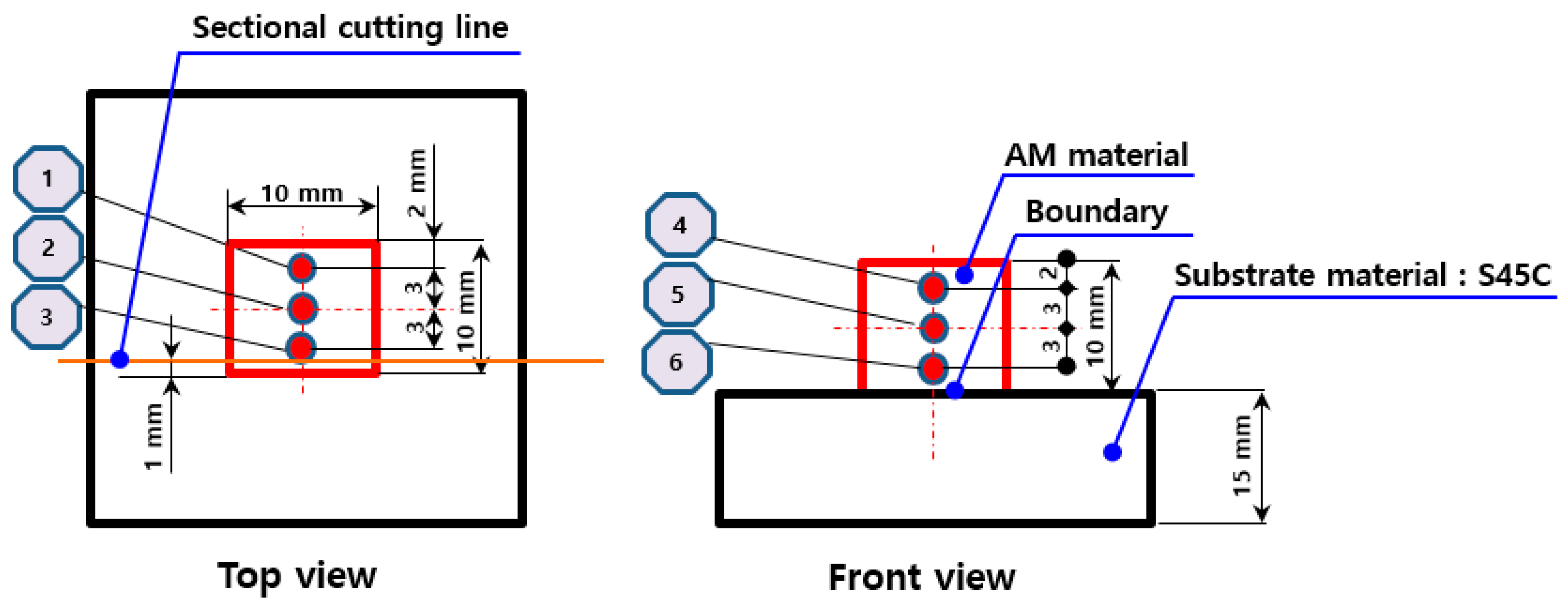
In this study, the change in the hardness of the printed material with respect to changes in the laser power and powder supply amount was studied for the two types of metal powder materials. Figure 2 shows the specimen production shape applied to the test and the location of the hardness measurement of the AM output. Table 4 shows the main AM process conditions used in the evaluation of the change in hardness of the AM output with respect to the change in the laser output during AM for the two types of materials that were studied. Table 5 and Table 6 show the change in the hardness of the printed material with respect to the change in laser output and the change in powder supply during AM using the test materials.
For both materials, changes in the hardness value of the printed material with respect to changes in the laser power and powder supply were observed. Additionally, differences were observed in the hardness values measured in the surface portion and cross section of the prepared specimen. Based on changes in the process conditions of the materials that were studied, Table 7 outlines the process conditions that yielded the highest hardness values for the AM output. Both materials exhibited their best hardness values under a laser output of 350–450 W. These values were obtained through the production of specimens of a specific size using a specific piece of equipment with a 0.8 mm laser beam size. Therefore, the AM process conditions outlined in Table 7 were applied to the specimen production and shear steel production, from which the mechanical properties of the two metal powder materials were then evaluated.

2.3. Examination of Heat Treatment Process for AM Metal Powder Materials

Because the material manufactured via AM is melted at a high temperature and then rapidly cooled, it undergoes quenching during the manufacturing process, even without an additional heat treatment. Because of the characteristics of the manufacturing process, certain alloy powder materials can obtain high strength and hardness values via AM. However, these materials tend to have low toughness values because they do not undergo tempering, unlike in forging manufacturing processes, in where general heat treatment is applied. Additionally, for certain materials, there may be deviations in the mechanical properties of the surface and interior of the AM output. Based on the usage conditions, these deviations may cause damage to and shorten the lifespans of the printouts. When a commercial forging material is powdered and used for AM, it is possible to use the same heat treatment process that is normally used for forging material in cases where additional heat treatment is required. However, for metal powder materials used in AM, there is no separate forging material, and thus, further research and development regarding the heat treatment process is necessary.
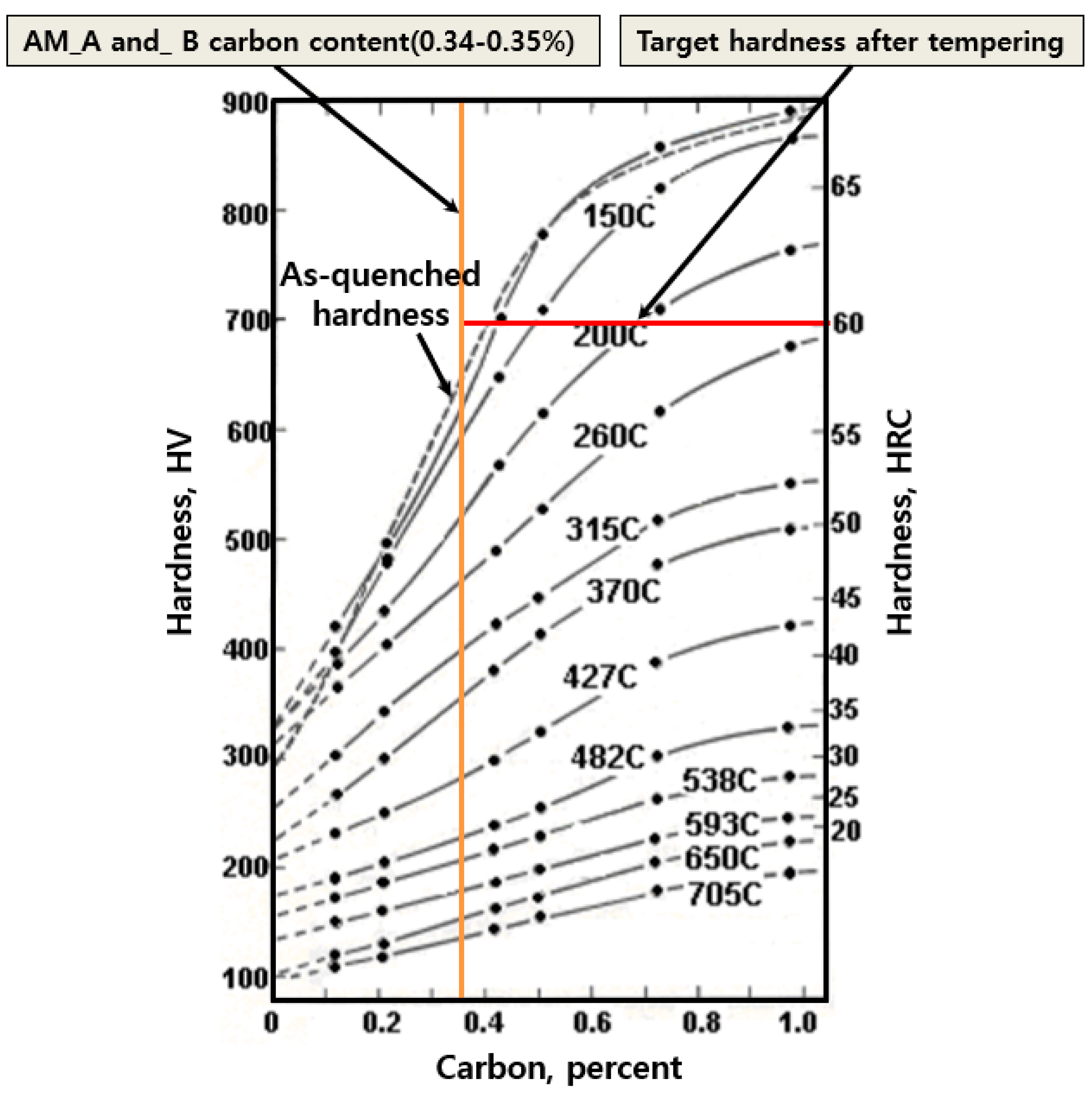
In this study, the quenching and tempering heat treatment processes for AM_A and AM_B after AM of the specimens were examined. The quenching and tempering processes were performed using a heat treatment furnace. In general, for a carbon tool-steel heat treatment, the tempering process is determined by the temperature and time. Furthermore, the appropriate temperature and time are selected according to the C content of the material and the alloy composition [18]. Figure 3 shows the interdependence of the tempering temperature with the C content of general C steel. This diagram shows the correlation between the C content and hardness after tempering at various temperatures for 1 h.
Holloman and Jaffe developed an equation for predicting the post-tempering hardness of alloy and C steels, known as the Holloman–Jaffe equation (more commonly referred to as the Larsom–Miller equation), which is expressed as Equation (3) [18]:
PH = TC (C + log t) 10−3,
where PH is the tempering parameter, t is the time at temperature TC (in Kelvin), and C is the material-dependent “Holloman–Jaffe” constant.
The quenching temperature during the heat treatment of general C tool steel was 1020–1060 °C, whereas the C content of AM_A and AM_B ranged within 0.34–0.35%. According to the results of the heat treatment studies through repeated experiments, the test materials were able to achieve an output internal and surface hardness of 60 HRC at a quenching temperature of 1030 °C. Figure 4 shows the parameters of the heat treatment process applied to AM_A and AM_B as derived from these repeated experiments.
The tempering temperature at which the impact properties of the material can be improved while minimizing the decrease in hardness was determined for the AM specimens that had undergone quenching. Generally, the tempering process for C tool steel is divided, based on temperature, into high-temperature and low-temperature tempering, with 200 °C as the point of distinction. The temperature range 350–370 °C results in brittleness and should be avoided. Therefore, tempering was performed for each temperature in the 150–400 °C range, with avoidance of the brittleness range. Further tempering was also performed in the 450–550 °C range to examine whether the material to be tested was capable of secondary hardening after tempering.
Figure 5 shows the hardness measurement results for the printed materials for each heat treatment condition, as determined via repeated experimentation. After the material was quenched at 1030 °C, there were no decreases in hardness under the low-temperature tempering condition of 150 °C, whereas some decreases in hardness occurred in the high-temperature tempering condition of 200 °C. Additionally, secondary hardening was not observed during the high-temperature tempering process at 450 °C or higher. Consequently, the hardness of AM_A was the highest at 150 °C in the low-temperature tempering stage after quenching, and the highest at 520 °C in the high-temperature tempering stage. Similarly, the hardness of AM_B was the highest at 150 °C in the low-temperature tempering stage after quenching, and the highest at 550 °C in the high-temperature tempering stage.

2.4. Shear Analysis

To properly manufacture the shear steel, the stress distribution generated during shearing was first analyzed through a finite element (FE) analysis. The plate material used in the stress analysis was a 1.2 mm thick B steel (22MnB5) with a tensile strength of 1.5 GPa. Additionally, the clearance of the upper and lower shear steels in the shearing process was 8% of the thickness of the material, because it is the most commonly applied clearance in the shearing of general thin-plate materials [19,20]. To determine the mechanical properties of the material required for the analysis, a tensile test was performed at a constant speed of 2 mm/min using an Instron 5988 universal testing machine (Instron, Norwod, MA, USA). Table 8 lists the average values, excluding the minimum and maximum values, from five repeated tests. Because mechanical trimming is performed after press hardening, the flow stress of press-hardened 22MnB5 used in the FE analysis of the mechanical trimming process was obtained via a tensile test. The mechanical properties of 22MnB5 and the process conditions used in the FE analysis are summarized in Table 9.
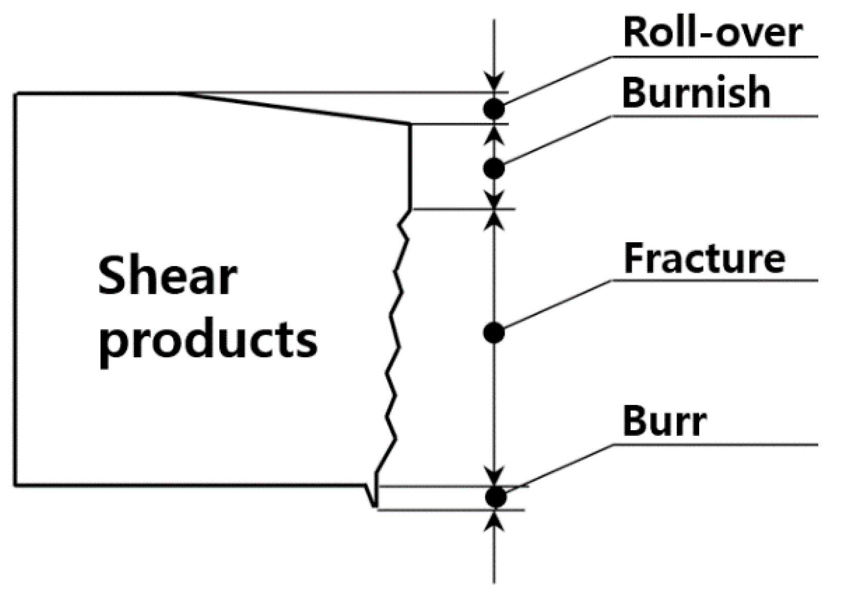
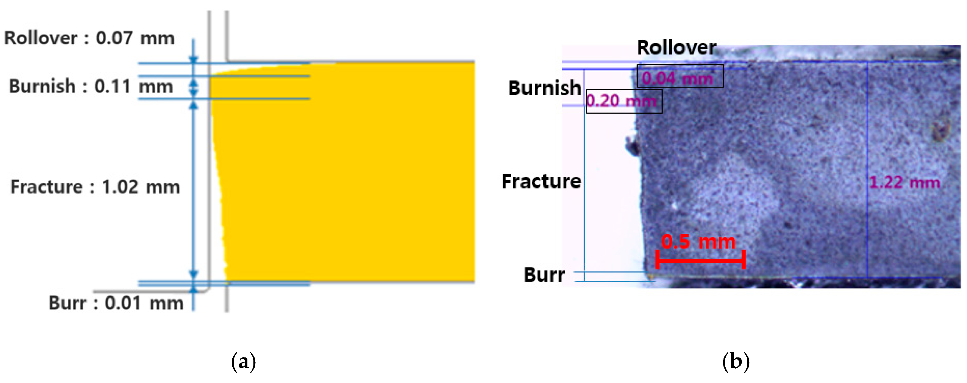
Figure 6 shows the shape of the shear surface that manifested during shearing. It is desirable to suppress burr generation because burring lowers workability and causes a gap with the mating material during bonding. These burrs are generally regulated to be less than 5–10% of the material thickness.
The shear of a metal plate is considered to be a form of ductile failure due to defect growth, and several theoretical studies have been conducted to simulate this phenomenon. A general type of damage model can be expressed as Equation (4):
C n o r m a l i z e d   C L   = F ( S 1 ,   S 2 , ) d ϵ ¯ ,
where d ϵ ¯ is the effective strain. Damage F is defined as a function of the process variables (Si), the values of which are integrated according to the deformation history. It was assumed that failure occurs when the accumulated damage value reaches the critical value C, which was applied accordingly. Although a variety of damage models have been proposed in a number of studies, the Cockcroft and Latham destructive models, which are known to be the most accurate through experimental verification, are the most widely used models for predicting ductile fracture during the shearing of shear steel with a simple shape [21]. The generalized Cockcroft and Latham fracture model is shown in Equation (5) [22]:
C n o r m a l i z e d   C L   = 0 ϵ ¯ f ( σ m a x σ ¯ )   d ϵ ¯ ,
where ε ¯ f is the fracture strain, σmax is the maximum principal stress, and σ ¯ is the effective stress. That is, in the Cockcroft–Latham model, the growth of damage increases with respect to the maximum principal stress in the tensile direction, where failure occurs when the value reaches a certain limit.
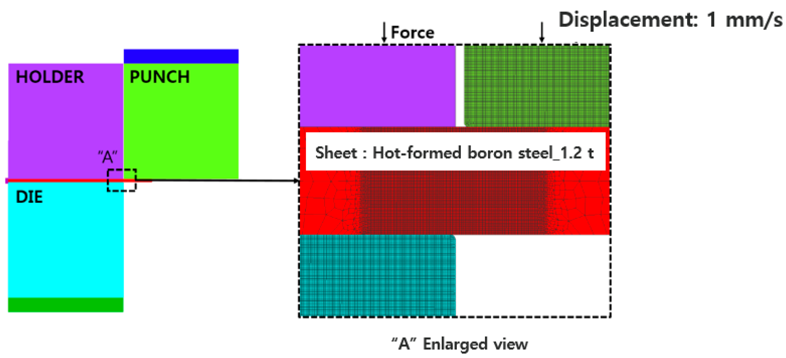
Figure 7 shows the shear analysis concept applied to the stress analysis. The ductile failure threshold of the material used in the fracture analysis was 0.8, which was derived from a finite element analysis of the shear test and using a correlation method between the test and analysis [23]. The physical property values obtained from the tensile test were used as the input. The analysis was performed with variations in the critical damage coefficient to obtain a coefficient that matched the length of the components of the cut surface, such as the pressed, shear, and fracture surfaces; this coefficient was regarded as the critical damage coefficient. Figure 8 shows the shear analysis and test for deriving the critical damage factor C.
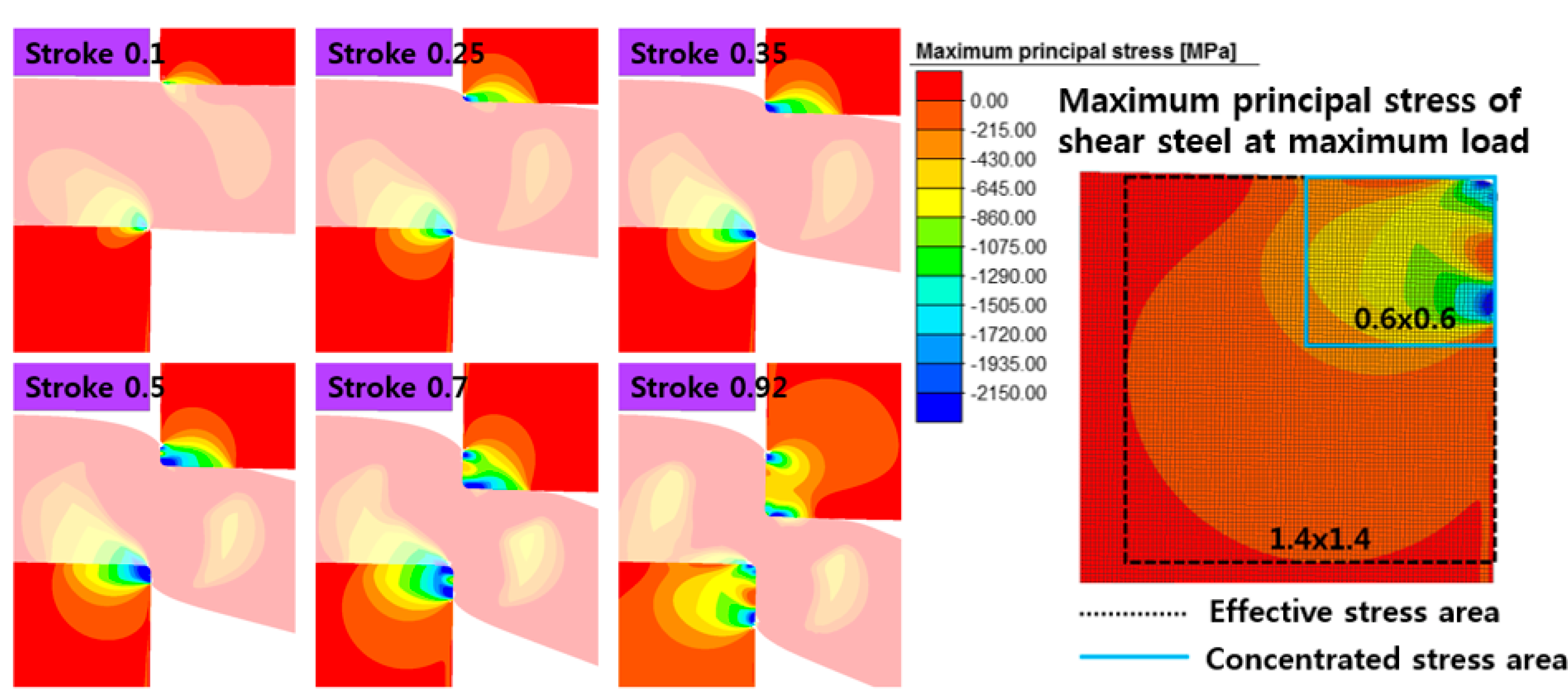
Figure 9 shows the results of the stress analysis on the shear steel blade derived from the shear analysis. The analysis showed that a compressive stress acts as the maximum principal stress in the upper and lower shear steels during shearing. In this study, the maximum stress generated during one shearing operation was 2150 MPa. Additionally, the area where the concentrated stress occurs during shearing was approximately 0.6 mm into the shear blade, and the effective stress generation range was analyzed to be approximately 1.4 mm.

2.5. Mold Fabrication

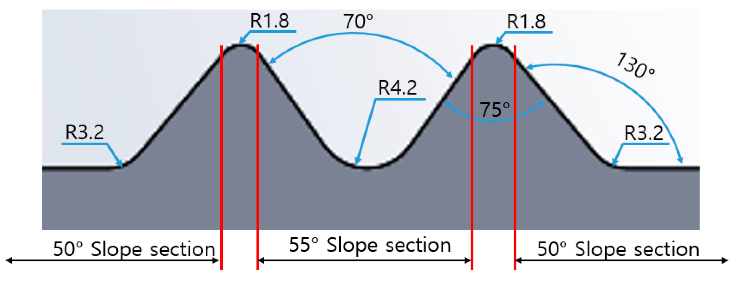
In the general shearing of hot stamping parts, flat and inclined shearing processes are performed simultaneously. In this study, it was decided that, for each material, the shear test should be continuously conducted for more than 100,000 cycles or until the shear steel underwent breakage. The life evaluation was conducted in an inclined shear condition to more closely mimic the harsh environment encountered in mass production. The shear steel manufacturing concept was established based on the shear analysis results, as shown in Figure 10. Figure 11 shows the slope shear condition concept. The mold was manufactured such that early breakage of the shear steel could be induced during shearing. Additionally, to simultaneously shape the product to be sheared and to enable the performance of shear life evaluation, the process was designed to be of a progressive type, in which molding and shearing processes could be performed simultaneously in one mold.
Figure 12 shows the finished shear steel and the mold manufactured for the life evaluation. The materials and conditions involved in the evaluation included Forging_C; a comparison of the relative lives of shear steel produced with and without application of heat treatment to AM_A and AM_B; and laminated and forged materials. Table 10 outlines the application conditions for each material subjected to the shear life evaluation in inclined shear conditions.
The shear life evaluation was conducted based on a target life of 100,000 cycles, while satisfying the condition that the amount of burr generated by the plate material, due to abrasion and breakage of the shear steel during the shearing operation, remained within 10% of the material thickness. Accordingly, it was necessary to perform repeated shearing work exceeding 500,000 cycles, whereas the B steel used for the hot stamping was heated to 900 °C or higher, and then cooled to obtain a tensile strength of 1.5 GPa. Therefore, a shear test was performed using a cold-rolled sheet of Docol 1500 M manufactured by SSAB of Sweden, which has a tensile strength similar to that of B steel, and a B steel sheet. The press was stopped at 20 cycles, and then, at every 1000, 3000, 5000, and 10,000 cycles, which were selected as specific points in time for the shear life evaluation. For comparison, the B steel material was also subjected to the test. The B steel, which was manufactured using a separate heating furnace and cold press, was heated to 950 °C in the heating furnace for 5 min under hot-stamping mass-production conditions, and then cooled in the cold press at 5 °C for 1 min to prepare the specimen. Table 11 and Table 12 list the main alloy components and mechanical properties of Docol 1500 M. Additionally, Table 13 lists the main process conditions applied in the shear life evaluation. Figure 13 shows the heating furnace and cooling press used for the specimen production, whereas Figure 14 shows the mass production line of the 140 ton mechanical press used in the shear life evaluation.

3. Results

3.1. Evaluation of AM_A, AM_B, and Forging_C Mechanical Properties

The main mechanical properties of shear steel include compressive strength, hardness, toughness, and tensile strength. In this study, the main mechanical properties of the two types of laminated materials and the comparative material Forging_C were compared and evaluated.

3.1.1. Tensile Strength Evaluation of AM Materials

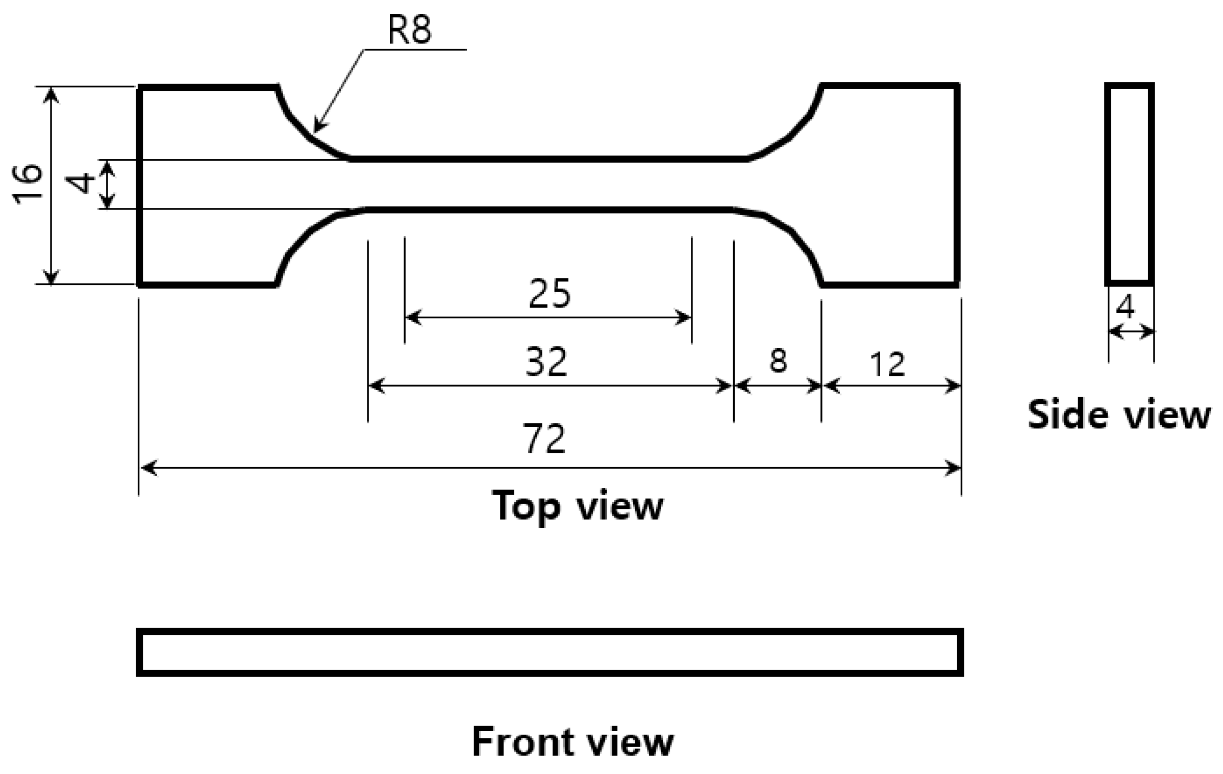
A tensile test was performed on AM_A and AM_B after the AM process using a universal testing machine (Instron 5988, Instron, Norwod, MA, USA). Figure 15 shows the shape and detailed dimensions of the tensile specimen subjected to the tensile tests. Tensile testing was performed at a rate of 1 mm/min. After five samples of each AM output were tested, the minimum and maximum values were discarded, and the average value of the remaining three was recorded.
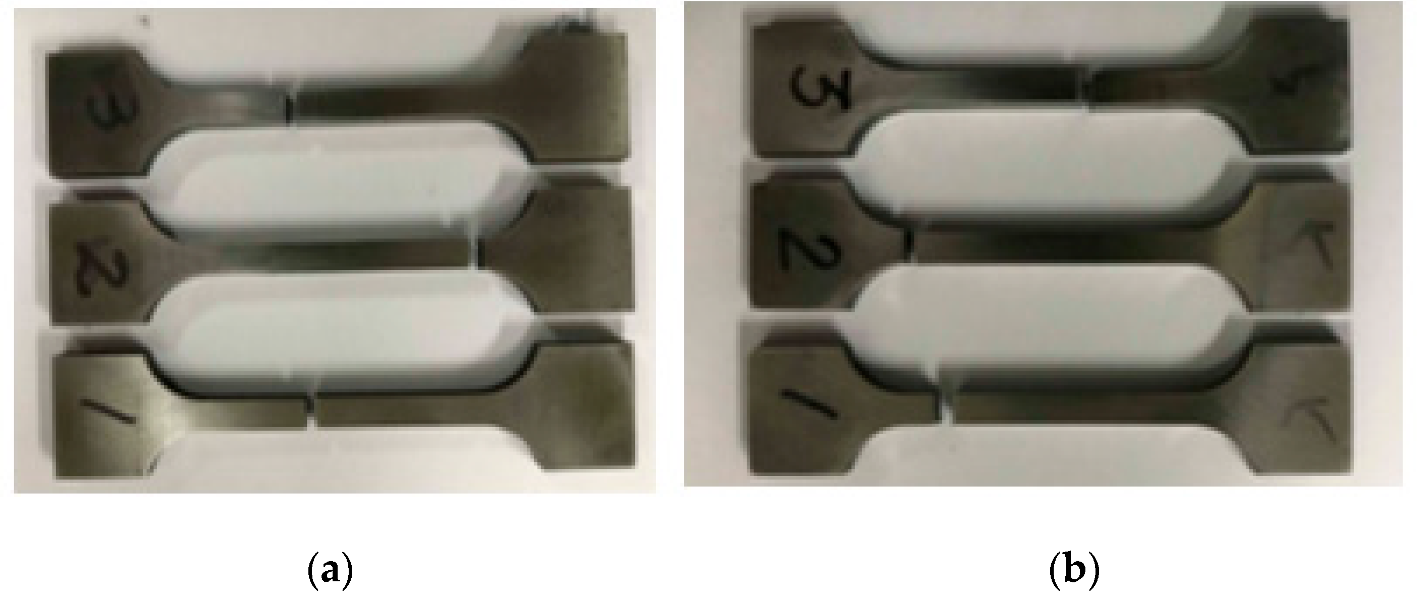
Figure 16 shows the fracture locations of the tensile specimens after the test was completed, whereas Table 14 outlines the tensile test results. The average tensile strength and elongation of AM_A were 1820 MPa and 8.44%, respectively, whereas those of AM_B were evaluated to be somewhat lower.

3.1.2. Bonding Strength Evaluation of AM Materials

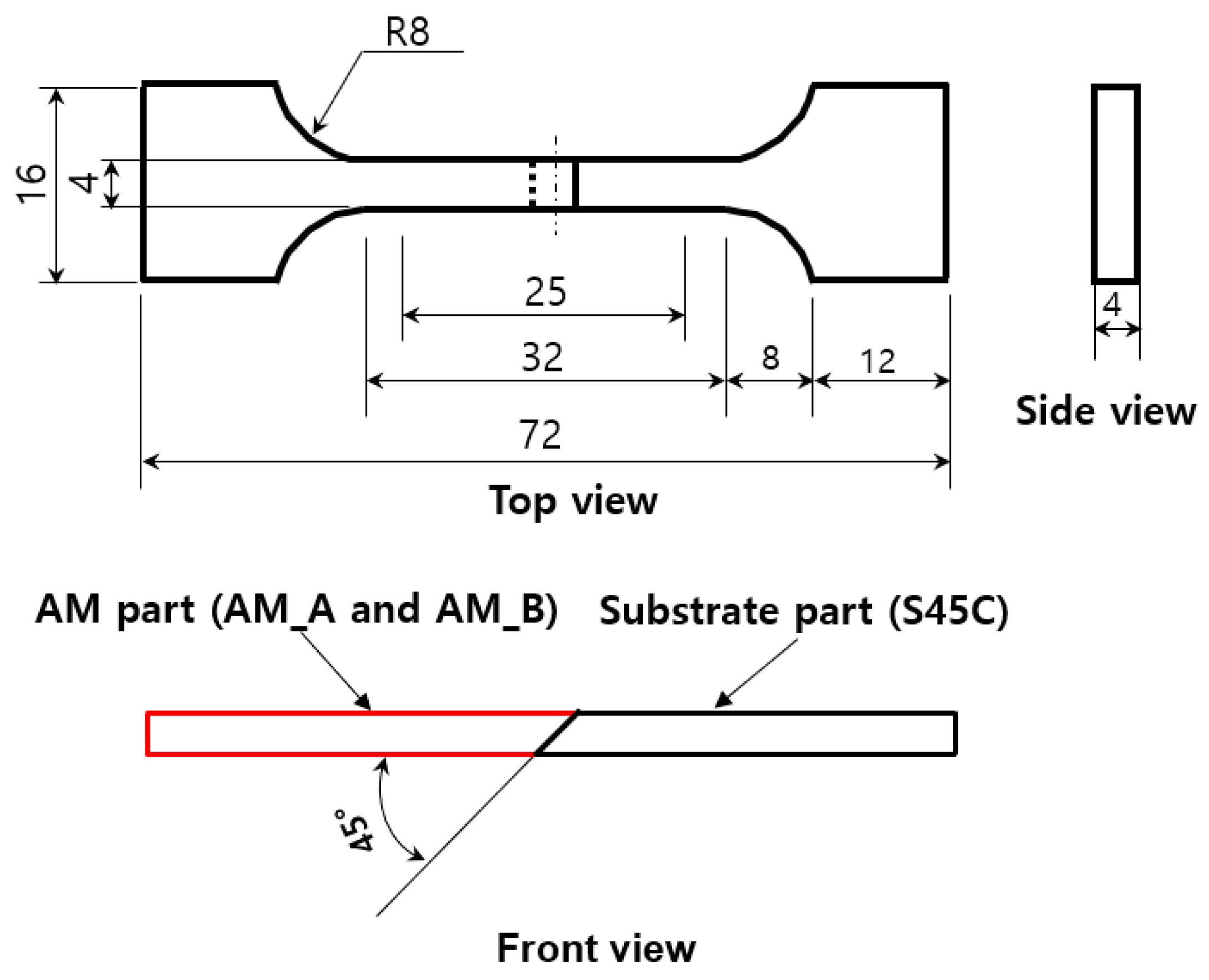
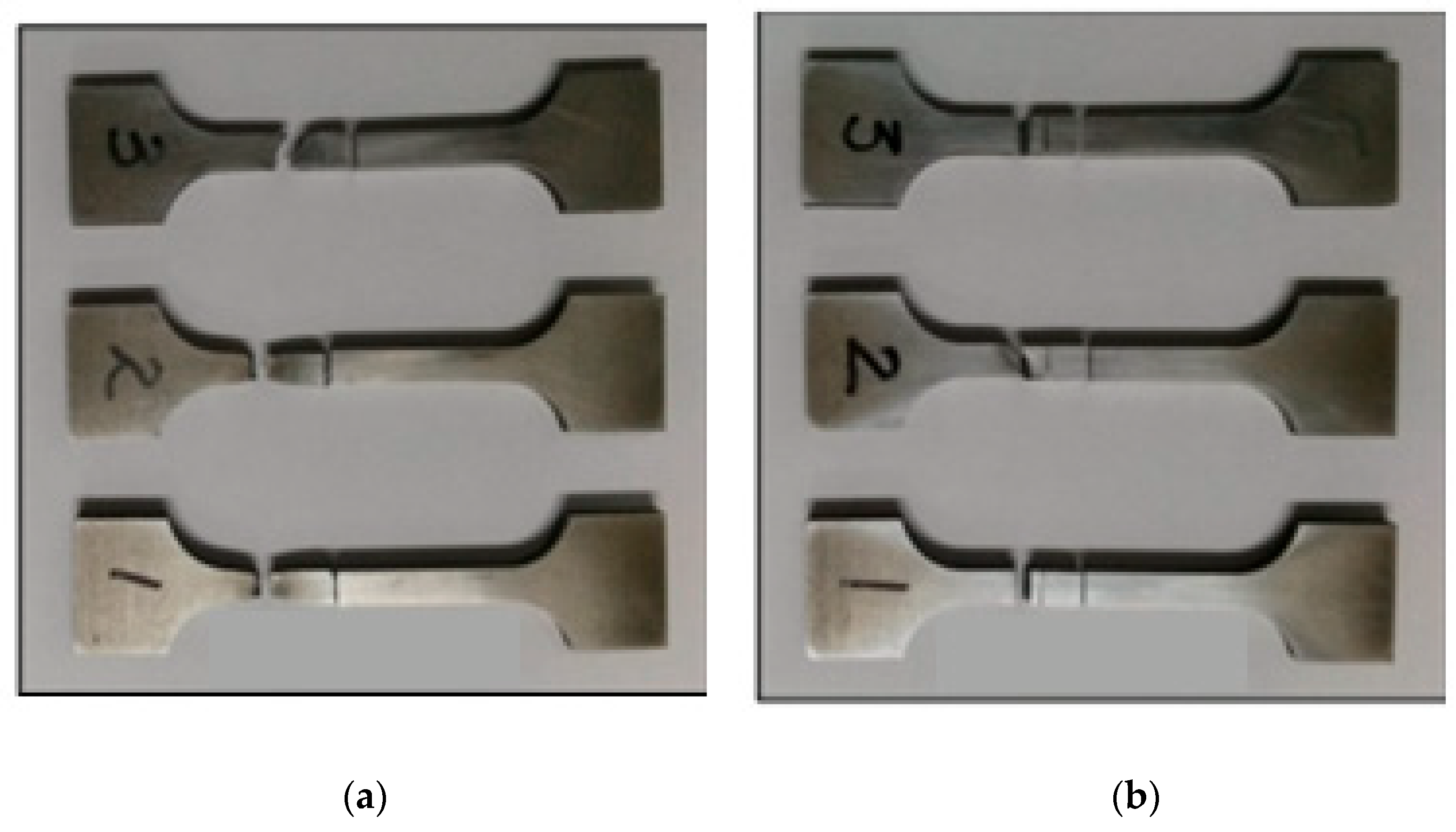
In this study, the shear molds were divided into functional and non-functional parts, with the objective of improving their material use efficiency during their manufacture. For this, it was necessary to evaluate the bonding strength of the functional part to which AM was applied and of the non-functional part as the base material. Therefore, a low-cost S45C material, which is generally used in the non-functional parts of shear molds, was selected as the base material. After the bonding specimen was manufactured using AM, the bonding strength of each material was evaluated. Figure 17 shows the bonding specimen manufacturing details and its detailed dimensions, whereas Figure 18 shows photographs of the specimens after the test was completed.
After five samples of each AM output were subjected to tensile testing, the minimum and maximum values were discarded, and the average value of the remaining three was recorded. Table 15 outlines the bonding strength evaluation results for the two materials. The bonding strength was evaluated to be in the range of 575–647 MPa. A tensile strength of 569 MPa was achieved for the non-heat-treated S45C, whereas that achieved for the heat-treated and tempered S45C was 690 MPa [19]. Although a separate heat treatment process was not applied to the S45C base material, the interface was partially heated during the bonding specimen manufacturing via AM. Additionally, it was demonstrated that both types of laminated materials achieved a bonding strength of at least 80% of the base material value.

3.1.3. Unnotched Impact Test Evaluation of AM_A, AM_B, and Forging_C

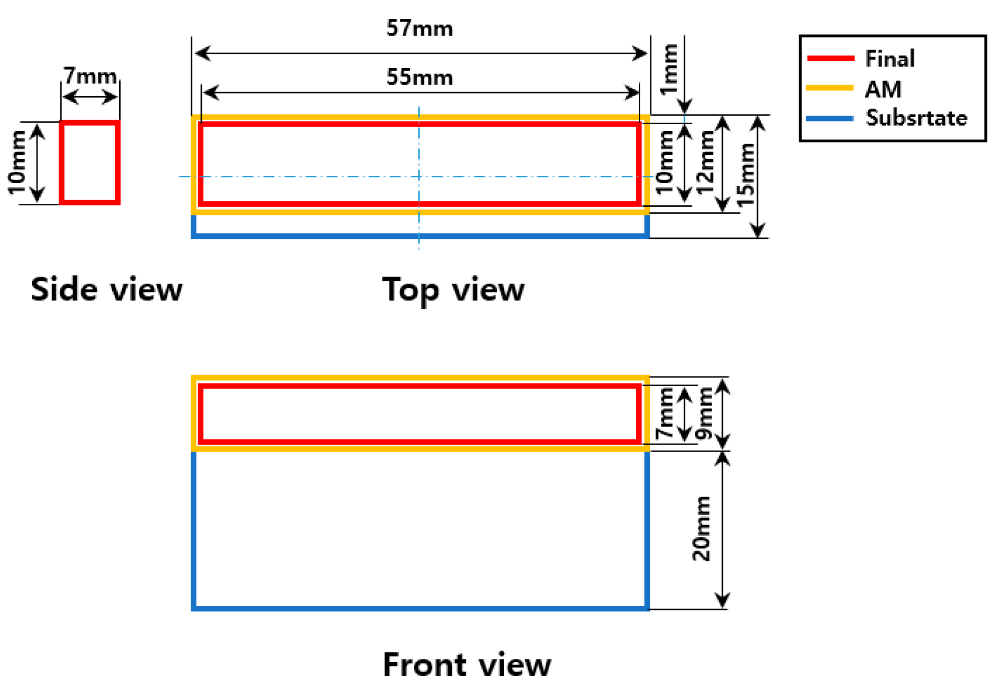
The impact test is important for evaluating the toughness of mold steel materials. For this test, each impact specimen was prepared according to the heat treatment and nonheat treatment conditions of the AM materials. Moreover, to quantitatively evaluate the impact test values of the AM and forged materials, Forging_C was selected as the comparative material, and the impact values of all the materials were evaluated through an unnotched impact test. Figure 19 shows the shape and detailed dimensions of the impact specimen. The specimens for impact testing were prepared on the S45C substrate using heterogeneous metal AM. Additionally, with the surface roughness after AM taken into consideration, the specimens were prepared with a processing allowance. As a result, 55 × 10 × 7 mm unnotched impact specimens were manufactured via wire processing and abrasive processing. Seven test specimens were prepared for each combination of material and condition.
An MPX-700 Charpy impact tester was used for the impact tests. For each material–condition combination, after five samples (from among the seven specimens) were tested, the minimum and maximum values were discarded, and the average of the remaining three was recorded. Table 16 outlines each material and manufacturing condition with the corresponding test results. The heat-treated Forging_C exhibited the highest impact value, whereas the AM_B laminated material exhibited superior impact properties, equivalent to 85% that of Forging_C. By contrast, the impact test value of AM_A was very low, at 20% of the Forging_C value. Generally, the impact properties of forging materials are improved when a material that has undergone quenching is tempered. However, in the case of the tested laminated materials, the impact values of the non-heat-treated materials were higher than those of the tempered specimens. Furthermore, generally, high-temperature tempering conditions yield higher impact values than those produced in low-temperature tempering conditions. By contrast, the hardness and impact test values of the tested AM materials were high under the low-temperature tempering condition. This was expected as a result of the quenching of the AM material through the additional heat treatment process, in which primary quenching occurred during AM. This is considered to have been caused by differences in the alloy compositions and manufacturing processes of the forging and laminate materials.

3.1.4. Microstructural Analysis of AM_A, AM_B, and Forging_C

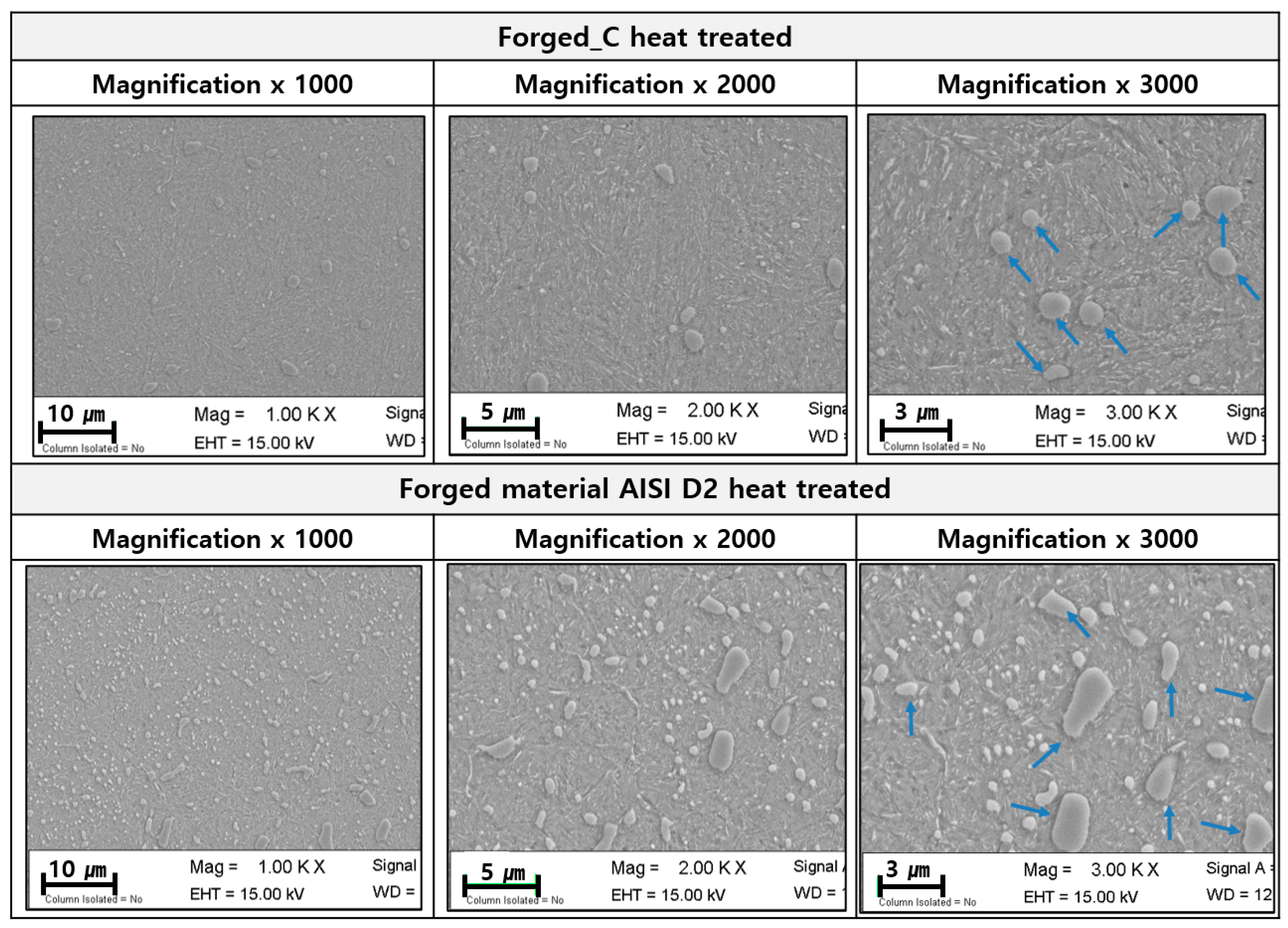
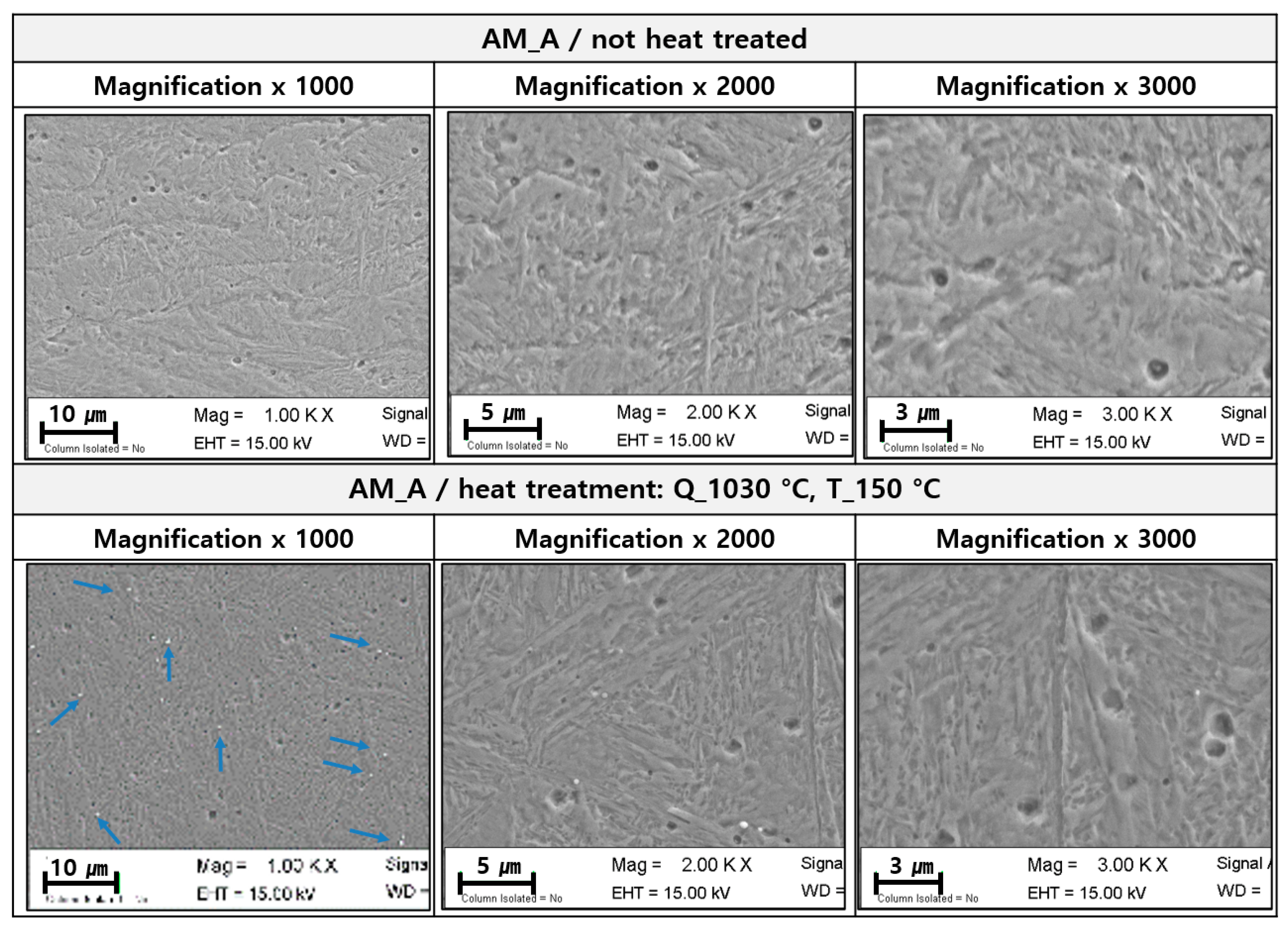
A field-emission scanning electron microscopy (FESEM) Gemini 300 (Carl Zeiss NTS Ltd., Jena, Germany) was used to analyze the metallographic properties of the forged and AM materials. Figure 20 shows the metallurgical structures of the commercial forged alloy tool steel D2 and Forging_C after heat treatment. Precipitated phases were irregularly precipitated in the matrix of the heat-treated forged materials. Additionally, the precipitated phases of Forging_C were smaller and more finely distributed than those of the D2 material. Figure 21 shows the microstructures of the heat-treated and non-heat-treated AM_A specimens. No precipitation phases were observed in the matrix structure of the non-heat-treated AM_A specimen. By contrast, it was observed that a number of precipitation phases were finely precipitated in the matrix structure of the heat-treated AM_A specimen because of the quenching effect.
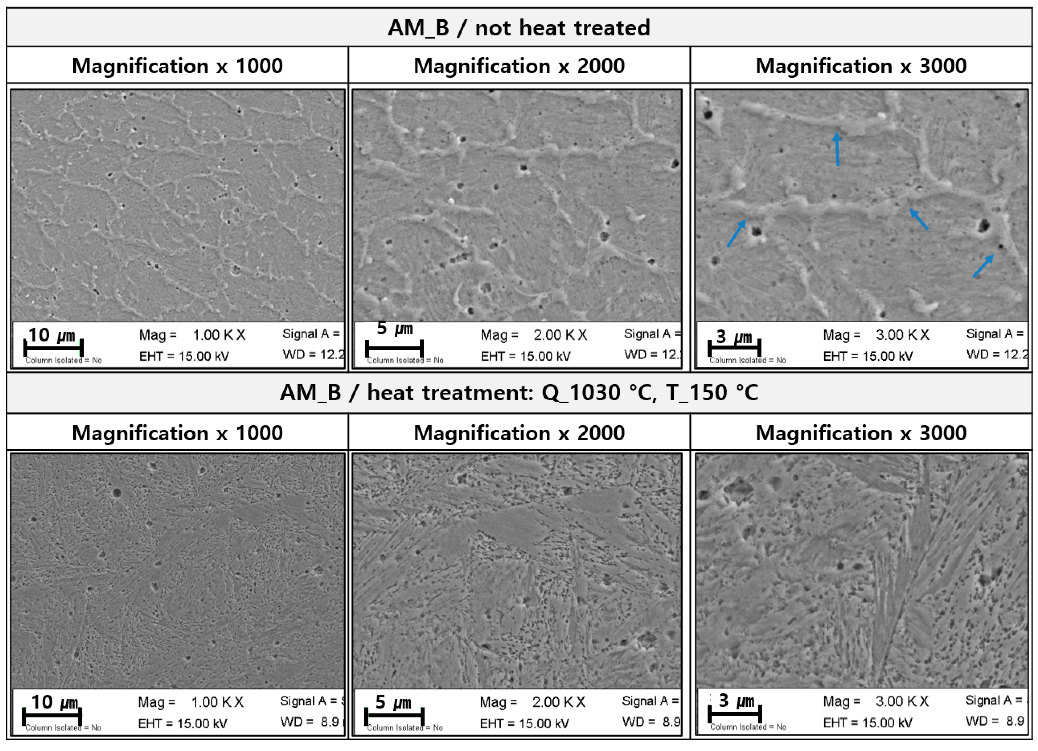
Figure 22 shows the microstructures of the heat-treated and non-heat-treated specimens of AM_B. The precipitation phases in the non-heat-treated AM_B specimen were precipitated along the grain boundaries in the matrix structure. Furthermore, the precipitation phases that appeared in the matrix structure of the non-heat-treated AM_B specimen were reduced by the heat treatment. This is considered to be characteristic to each material based on the application of the heat treatment process. Additionally, according to the microstructural comparison between the forged and AM materials, the precipitated phases in the forged material were precipitated in irregular shapes and sizes in the matrix structure upon the application of heat treatment. By contrast, the precipitated phases in the AM materials were precipitated in a specific pattern along the grain boundaries in the matrix structure. This is attributed to the difference in the alloy composition and the manufacturing processes of the forged and AM materials. It is anticipated that these microstructural and mechanical properties will affect the lifetime of each material.

3.2. Mold Life Evaluation

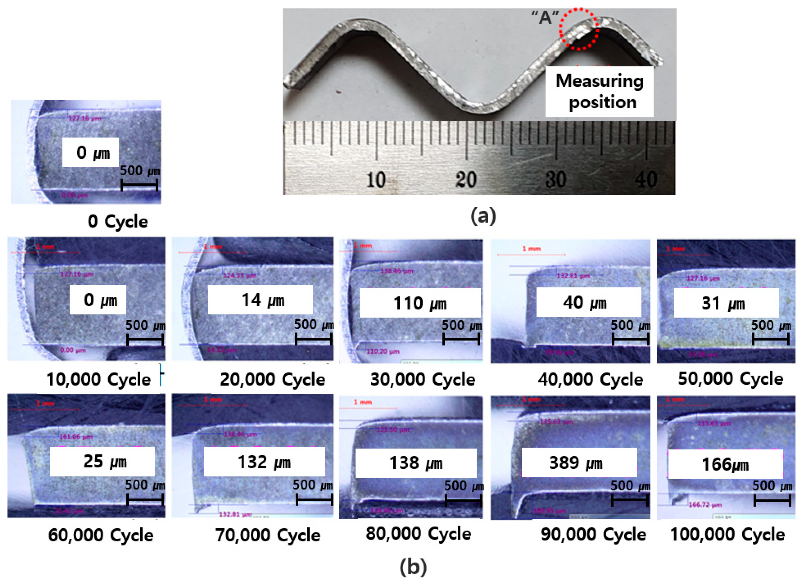
Figure 23 shows the wear and breakage of the shear steel blades and the shear life evaluation results for each combination of material and condition. Figure 24 shows the amount of wear and breakage of the shear steel made of non-heat-treated AM_A and heat-treated Forging_C after 90,000 shearing cycles. Based on the analysis of the amount of wear and breakage, Forging_C exhibited the best wear characteristics, whereas AM_A exhibited the best breakage characteristics. Figure 25 shows the number of burrs generated by 100,000 shearing cycles of the shear steel composed of non-heat-treated AM_A material. Unlike in the planar shear condition, the experimental procedure of the inclined shear test was such that molding and shearing were performed together. However, the experiment confirmed that the shear life evaluation was conducted in a state where the material was incompletely seated during some of the shearing work because of the occurrence of springback in the forming process, even though sequential forming was applied. Because of this, the amount of burr generation was irregular. Therefore, the lifetime evaluation was conducted with the amount of burr generated during shearing and the abrasion and breakage of the sheared steel comprehensively taken into consideration. During the shearing operation, the two heat-treated AM materials exhibited no improvement in their lifetimes relative to those of the non-heat-treated materials. Among the five experimental conditions, the non-heat-treated AM_A material and the heat-treated Forging_C material were evaluated as having the best lifetimes.

4. Conclusions

In this study, a low-cost, high-functionality shearing mold manufacturing method using heterogeneous material AM for the efficient shearing of 1.5 GPa grade hot-stamped automobile body parts were studied, resulting in the following conclusions:
(1)
Two functional metal alloy powders that could be used in the functional parts of shear steel were developed based on the main principles of the metal AM process, the alloy components of the commercial forging material, and the hardness values after heat treatment. The developed material was able to achieve a hardness of 58 HRC or higher via AM without the application of heat treatment, unlike for a commercial mold steel forged material.
(2)
To improve the mechanical properties of the developed metal powder material after AM, the changes in mechanical properties due to the application of heat treatment were evaluated via an impact test after the application of heat treatment. No improvement was observed in the impact test results for the heat-treated AM material relative to those for the non-heat-treated material. It was determined that the mechanical properties of the material did not improve even when additional heat treatment was applied to the laminated material, because of the occurrence of quenching after melting at a high temperature during the manufacturing process.
(3)
After evaluation of the various mechanical properties of Forging_C, which is known to have the best mechanical properties required for shear steel among laminated and commercial forging materials presently available, a shear lifetime evaluation was conducted to test the durability of the AM materials for 100,000 cycles. The AM_A material was determined to have a durability of 90,000 cycles, similar to that of Forging_C. However, the impact value of AM_A, which is an important mechanical property required for shear steel, was evaluated to be as low as 20% of that of Forging_C when compared at similar hardness values. Therefore, it was concluded that the lifespan of the AM_A shear steel does not appear to be in proportion to the mechanical properties. To investigate this discrepancy, the microstructures of the laminated and forged materials were observed using FESEM. For the forged material, precipitated phases were observed to be irregularly precipitated in the matrix structure, which was dependent on the application of heat treatment. By contrast, for the laminated materials, precipitated phases were either not observed or were observed to be precipitated in a regular pattern along the grain boundaries in the matrix structure. Therefore, it was concluded that the lifespan of the shear steel was affected by the distribution and characteristics of the microstructure, along with the mechanical properties of the material.
(4)
The shear steel composed of the non-heat-treated AM_A material and that composed of the heat-treated Forging_C material exhibited the highest lifetimes. However, because the Forging_C material is from three to four times more expensive than D2, its commercial application is limited by the high mold manufacturing costs. By contrast, the AM material can be applied using the newly developed method on 1–2% of the functional parts of S45C, which is 70–80% cheaper than D2 and is used for 98–99% of the non-functional parts of all shear steel. Therefore, relative to conventional techniques, the newly developed method reduces the mold manufacturing cost. Additionally, based on both the mold manufacturing period and maintenance convenience, commercialization of the proposed method is possible.

Funding

This study has been conducted with the support of the Korea Institute of Industrial Technology as “Development of intelligent root technology with add-on modules” (kitech Eo-21-0009), Korea, MOTIE, (project No. 20009839) and also the Ministry of SMEs and Startups, New Technology Development with Purchase Condition Project (S2860926).

Acknowledgments

The authors would like to thank those associated with co-research organizations (Shinyoung Co., Ltd. and Andong National University in South Korea).

Conflicts of Interest

The author declares no conflict of interest.

References

  1. Lee, C.M.; Kim, J.H.; Oh, W.J.; Ryu, B.H. A Study on the Analysis for Upper Seat Track of Automobile Using 1180 MPa Ultra-High Strength Steel. J. Korean Soc. Precis. Eng. 2017, 34, 525–531. [Google Scholar] [CrossRef]
  2. Murata, T.; Hamamoto, S.; Utsumi, Y.; Yamano, T.; Futamura, Y.; Kimura, T. Characteristics of 1180 MPa grade cold-rolled steel sheets with excellent formability. Kobelco Technol. Rev. 2017, 45, 17–20. [Google Scholar]
  3. Uemori, T.; Naka, T.; Tada, N.; Yoshimura, H.; Katahira, T.; Yoshida, F. Theoretical predictions of fracture and springback for high tensile strength steel sheets under stretch bending. Procedia Eng. 2017, 207, 1594–1598. [Google Scholar] [CrossRef]
  4. Kim, J.S.; Jo, N.H. Lightweight Materials for Automotive; Technology Trend Report; KISTI: Seoul, Korea, 2018. [Google Scholar]
  5. Choi, H.S. Vehicle Lightweight Technology Transferred from Aircraft. KAMA Web J. 2016, 325. [Google Scholar]
  6. Size, A.M. Share and Trends Analysis Report by Form (Blanket, Particle, Panel, Monolith), by Product (Silica, Carbon, Polymers), by End Use, by Technology, by Region, and Segment Forecasts, 2018–2025. Grand View Research. Available online: https://www.giikorea.co.kr/report/bc1044191-global-market-plastics-compounding.html (accessed on 8 January 2021).
  7. Jung, I.S.; Moon, M.S. Development Trends and Applications of Lightweight Carbon Composites for Automobiles; Information Analysis Report; KISTI: Seoul, Korea, 2015; pp. 18–26. [Google Scholar]
  8. Choe, S.B.; Kim, S.W.; Jeong, S.K. Automotive Lightweight Technology Trends and Development Strategies; Information Analysis Report; KISTI: Seoul, Korea, 2013; pp. 1–7. [Google Scholar]
  9. Won, S.T.; Kim, J.D.; Kim, D.U.; Kim, G.H.; Yoon, G.S. Trends of Press Forming Industry and Technology. Trans. Mater. Process. 2014, 23, 392–396. [Google Scholar]
  10. Nakagawa, Y.; Mori, K.I.; Maeno, T.; Umemiya, R. Delayed cracking in hot stamping with hot trimming for ultra-high strength steel components. Int. J. Adv. Manuf. Technol. 2019, 105, 5081–5090. [Google Scholar] [CrossRef]
  11. Maeno, T.; Mori, K.I.; Nagai, T. Improvement in formability by control of temperature in hot stamping of ultra-high strength steel parts. CIRP Ann. 2014, 63, 301–304. [Google Scholar] [CrossRef]
  12. Choi, H.S.; Kim, B.M.; Kim, D.H.; Ko, D.C. Application of mechanical trimming to hot stamped 22MnB5 parts for energy saving. Int. J. Precis. Eng. Manuf. 2014, 15, 1087–1093. [Google Scholar] [CrossRef]
  13. Cora, Ö.N.; Koç, M. Experimental investigations on wear resistance characteristics of alternative die materials for stamping of advanced high-strength steels (AHSS). Int. J. Mach. Tools Manuf. 2009, 49, 897–905. [Google Scholar] [CrossRef]
  14. Mussa, A.; Krakhmalev, P.; Şelte, A.; Bergström, J. Development of a New PM Tool Steel for Optimization of Cold Working of Advanced High-Strength Steels. Metals 2021, 10, 1326. [Google Scholar] [CrossRef]
  15. Arieta, F.; Netto, E.B.; Reguly, A.; Pannes, W.K.; Beutler, U.; van Soest, F.; Ernst, C. Impact properties of vacuum heat treated AISI D2 and 8% Cr cold work tool steels. J. ASTM Int. 2011, 8, 1–12. [Google Scholar] [CrossRef]
  16. Kang, J.Y.; Kim, H.; Son, D.; Lee, J.J.; Yun, H.Y.; Lee, T.H.; Park, S.K. Microstructures and Mechanical Characteristics of Advanced Cold-Work Tool Steels: Ledeburitic vs. Matrix-type Alloy. J. Korean Soc. Heat Treat. 2015, 28, 181–189. [Google Scholar] [CrossRef] [Green Version]
  17. Bohler-Uddeholm Product Specification Sheet for Caldie Tool Steel. Available online: https://www.uddeholm.com/files/PB_caldie_english.pdf (accessed on 8 January 2020).
  18. Canale, L.C.; Yao, X.; Gu, J.; Totten, G.E. A historical overview of steel tempering parameters. Int. J. Microstruct. Mater. Prop. 2008, 3, 474–525. [Google Scholar] [CrossRef]
  19. Ostergard, D.E. Basic Diemaking; McGraw-Hill Book Co. Inc.: New York, NY, USA, 1963; pp. 3–13. [Google Scholar]
  20. Schubert, P.B. Die Methods; Industrial Press: Norwalk, CT, USA, 1966. [Google Scholar]
  21. Lou, Y.; Piao, M.; Huh, H. Evaluation of Ductile Fracture Criteria in Full Stress States. In Proceedings of the KSTP Spring Conference, Cheju Island, Korea, 15 January 2012; pp. 213–216. [Google Scholar]
  22. Cockcroft, M.G.; Latham, D.J. NEL Report No. 240; National Engineering Laboratory: Glasgow, UK, 1966. [Google Scholar]
  23. Kwak, J.H. Prediction of the Shear Fracture and Parameter Study for an Auto-Part with AHSS using the Finite Element Forming Analysis considering Sheared Edge, Doctoral dissertation. Master’s Thesis, Daegu University, Gyeongbuk, Korea, 2015. [Google Scholar]
  24. Product Specification Sheet for Docol 1500 M Steel. Available online: https://www.ssab.com/products/brands/docol/products/docol-1500M/SSAB (accessed on 8 January 2020).
Figure 1. Comparison of relative weights and costs of lightweight materials to those of general mild steel [8,9].
Applsci 12 01158 g001
Figure 2. Specimen manufacturing shape and hardness measurement locations.
Applsci 12 01158 g002
Figure 3. Hardness of tempered martensite in Fe-C steel [18].
Applsci 12 01158 g003
Figure 4. AM_A and AM_B heat treatment process.
Applsci 12 01158 g004
Figure 5. Hardness measurement results for each heat treatment condition.
Applsci 12 01158 g005
Figure 6. Shape of shear surface produced by shear processing.
Applsci 12 01158 g006
Figure 7. Stress analysis concept during shearing work.
Applsci 12 01158 g007
Figure 8. Procedure for obtaining critical damage value via correlation method: (a) Finite element method analysis result; (b) actual shear test result.
Applsci 12 01158 g008
Figure 9. Stress analysis results for the shearing operation.
Applsci 12 01158 g009
Figure 10. Shear steel manufacturing concept based on AM technology.
Applsci 12 01158 g010
Figure 11. Detailed dimensions of shear steel with slope angles.
Applsci 12 01158 g011
Figure 12. Mold manufactured for the shear life evaluation in slope shear conditions: (a) Shear steel non-functional region substrate fabrication; (b) shear steel functional region additive manufacturing; (c) surface machining after additive manufacturing; (d) assembly in shear steel mold.
Applsci 12 01158 g012
Figure 13. 1.5 GPa specimen production heating furnace, cooling press, and heat-treated and quenched specimen.
Applsci 12 01158 g013
Figure 14. Mass production press line used in the shear life evaluation.
Applsci 12 01158 g014
Figure 15. Tensile test specimen shape and dimensions. All dimensions in mm.
Applsci 12 01158 g015
Figure 16. Fracture locations of AM material tensile specimens: (a) AM_A; (b) AM_B.
Applsci 12 01158 g016
Figure 17. Bonding specimen manufacturing details and associated dimensions. All dimensions in mm.
Applsci 12 01158 g017
Figure 18. Fracture locations of bonding-strength test specimens of AM materials: (a) AM_A; (b) AM_B.
Applsci 12 01158 g018
Figure 19. Shape and dimensions of unnotched impact test specimens.
Applsci 12 01158 g019
Figure 20. FESEM photographs of metallurgical structures of commercial tool-steel forgings.
Applsci 12 01158 g020
Figure 21. FESEM photographs of metallurgical structure of AM_A.
Applsci 12 01158 g021
Figure 22. FESEM photographs of metallurgical structure of AM_B.
Applsci 12 01158 g022
Figure 23. Shear life evaluation results (blade wear and damage condition) with respect to material condition.
Applsci 12 01158 g023
Figure 24. Comparison of wear and damage of upper shear steel after 100,000 shearing cycles: (a) Non-heat-treated AM_A; (b) heat-treated Forging_C.
Applsci 12 01158 g024
Figure 25. Burr generation amount of non-heat-treated AM_A material after 100,000 shearing cycles: (a) Shear section observation after 100,000 shearing operations; (b) enlarged view of part “A”.
Applsci 12 01158 g025
Table 1. Commercial tool steels used in mold manufacturing.
Steel GradeAISI or JISChemical Composition (wt/%)Heat Treatment and HardnessNote
CSiMnCrMoWVCoQ.T. (a)HRC
Flame-hardened steel23F850.70–0.720.86–1.000.02–0.780.17–1.010.08–0.16 0.07–0.19 Air56–60
KFH-10.75–0.800.95–1.050.70–0.801.00–1.100.20–0.25 0.03–0.05 Air56–60
Tool steelCarbon tool steelW1-101.050.200.30 Water57–63
Alloy tool steelSKS931.05 0.950.40 Oil57–63
SKS30.95 1.050.75-0.75 Oil57–60
D21.50 12.01.00 0.35 Air57–63
8% Cr steel1.001.000.408.002.00 0.30 Air57–63K340
High-speed tool steelM20.85 4.155.006.301.90 Oil58–64
SKH401.30 4.155.006.203.008.40Oil64–67S590
Matrix tool steelYXR 30.601.500.404.302.90 1.80 Oil58–61CALDIE, W360
(a) Q.T. = quenching and tempering.
Table 2. Main alloy components (wt.%) of materials examined in this study [17].
Material ClassificationCCrMnSiMoVFe
AM_A0.2–0.58–100.382.3 Balance
AM_B0.2–0.58–101.10.32.2 Balance
Forging_C0.75.00.50.22.30.5Balance
Table 3. Mechanical properties of Forging_C [17].
MaterialHardness
(HRC)
Young’s Modulus
(GPa)
Compressive
Yield Strength (MPa)
Forging_C60–612132230
Table 4. Main AM process conditions used in the evaluation of mechanical properties of AM outputs with respect to changes in heat input.
AM ParameterSample Name
AM_AAM_B
Supplied powder (g/min)4.40–7.305.00–7.30
Supplied powder gas (L/min)2.502.00
Supplied shield gas (L/min)7.007.00
Laser power (W)250–450250–450
Deposition speed (m/min)0.850.85
Deposition height per layer (mm)0.250.25
Deposition width pitch per layer (mm)0.500.50
Laser beam diameter (mm)0.800.80
Laser wavelength (nm)10601060
Table 5. Hardness measurement results for AM_A with respect to changes in heat input.
ConditionsLaser Power (W)Powder Supply (g/min)Average of 6 Measurements (HRC)
SurfaceSection
12507.353.740.7
23006.551.846.0
33505.559.754.4
44004.859.550.1
54504.458.551.5
Table 6. Hardness measurement results for AM_B with respect to changes in heat input.
ConditionsLaser Power (W)Powder Supply (g/min)Average of 6 Measurements (HRC)
SurfaceSection
12507.355.451.2
23007.058.443.9
33506.558.952.6
44005.458.153.4
54505.059.654.9
Table 7. Optimal AM process conditions for AM_A and AM_B.
AM ParameterSample Name
AM_AAM_B
Supplied powder (g/min)5.55.0
Supplied powder gas (L/min)2.502.00
Supplied shield gas (L/min)7.007.00
Laser power (W)350450
Deposition speed (m/min)0.850.85
Deposition height per layer (mm)0.250.25
Deposition width pitch per layer (mm)0.500.50
Laser beam diameter (mm)0.800.80
Laser wavelength (nm)10601060
Table 8. Mechanical properties of 22MnB5.
MaterialYield Strength
(MPa)
Tensile Strength
(MPa)
Elongation
(%)
22MnB5110015988.91
Table 9. Process conditions used in the FE simulation.
ConditionsValue
Clearance (mm)0.96
Tool steel velocity (mm/s)1
Friction factor0.1
Critical damage value0.8
Tool-steel compressive yield strength (MPa)2150
Minimum sheet element (mm)0.0125
Minimum tool element (mm)0.0156
Sheet flow stress (MPa) 2250 ϵ ¯   0.05
Table 10. Evaluation of applicable materials and application conditions.
Sample NumberApplied MaterialHeat Treatment
1Substrate S45C + Forging_CHeat treatment applied
2Substrate S45C +AM_ANo heat treatment
3Substrate S45C + AM_AHeat treatment applied
(Q, 1030 °C and T, 150 °C)
4Substrate S45C +AM_BNo heat treatment
5Substrate S45C + AM_AHeat treatment application
(Q, 1030 °C and T, 150 °C)
Table 11. Major alloy components of the Docol 1500 M [24].
CSiMnPSAlNb + TiCr + MoCuB
0.230.401.300.020.010.0151.001.000.200.01
Table 12. Mechanical properties of the Docol 1500 M [24].
MaterialYield Strength
(MPa)
Tensile Strength
(MPa)
Elongation
(%)
Docol 1500 M1220–15001500–17003
Table 13. Main process conditions applied in the shear life evaluation.
MaterialCoil Width
(mm)
Pitch
(mm)
Shear Speed
(Strokes per Minute)
Note
Docol 1500 M50440Applied to the initial 20 cycles and at specific cycles where the life evaluation was performed
B steel (22MnB5)501540Applied to the entire test except for a specific cycle where the life evaluation was performed
Table 14. AM specimen tensile test results.
Specimen
No
AM_AAM_B
Tensile Strength (MPa)Elongation (%)Tensile Strength (MPa)Elongation (%)
118738.7217137.37
217537.6217718.37
318368.9817497.93
Average18208.4417447.89
Table 15. AM specimen bonding-strength test results.
Specimen
No
AM_BAM_B
Tensile Strength (MPa)Elongation (%)Tensile Strength (MPa)Elongation (%)
16469.706359.52
26479.895069.40
36489.655849.48
Average6479.755759.47
Table 16. Impact test results for AM_A, AM_B, and Forging_C.
Specimen Manufacturing ConditionsShock Absorption Energy
(J)
Hardness
(HRC)
Forging_C/heat treatment applied104.059.8
AM_A/no heat treatment22.059.3
AM_A/heat treatment: Q_1030 °C, T_150 °C11.060.3
AM_A/heat treatment: Q_1030 °C, T_520 °C 6.357.8
AM_B/no heat treatment88.560.2
AM_B/heat treatment: Q_1030 °C, T_150 °C85.560.0
AM_B/heat treatment: Q_1030 °C, T_550 °C53.357.1
Publisher’s Note: MDPI stays neutral with regard to jurisdictional claims in published maps and institutional affiliations.