Article

Implementation of Robots Integration in Scaled Laboratory Environment for Factory Automation

1
The Institute for Artificial Intelligence Research and Development of Serbia, 21000 Novi Sad, Serbia
2
Faculty of Technical Sciences, University of Novi Sad, 21000 Novi Sad, Serbia
3
School of Engineering and Architecture, SRH University of Applied Sciences Heidelberg, 69123 Heidelberg, Germany
*
Author to whom correspondence should be addressed.
These authors contributed equally to this work.
Appl. Sci. 2022, 12(3), 1228; https://doi.org/10.3390/app12031228
Submission received: 2 December 2021 / Revised: 31 December 2021 / Accepted: 6 January 2022 / Published: 25 January 2022
(This article belongs to the Special Issue Smart Robots for Industrial Applications)

Abstract

:
Robotic systems for research and development of factory automation are complex and unavailable for broad deployment in robotic laboratory settings. The usual robotic factory automation setup consists of series of sensors, robotic arms and mobile robots integrated and orchestrated by a central information system. Cloud-based integration has been gaining traction in recent years. In order to build such a system in a laboratory environment, there are several practical challenges that have to be resolved to come to a point when such a system can become operational. In this paper, we present the development of one such system composed of (i) a cloud-based system built on top of open platform for innovation in logistics, (ii) a prototyped mobile robot with a forklift to manipulate pallets in a “factory” floor, and (iii) industrial robot ABB IRB 140 with a customized gripper and various sensors. A mobile robot is designed as an autonomous four Mecanum wheels system with on-board LiDAR and RGB-D sensor for simultaneous localization and mapping. The paper shows a use case of the overall system and highlights the advantages of having a laboratory setting with real robots for the research of factory automation in a laboratory environment. Moreover, the proposed solution could be scaled and replicated in real factory automation applications.

1. Introduction

The automation of warehouses and operation at factory floors is rapidly expanding. This process is enabled by the combination of industrial robots, mobile robotic systems, sensor networks and a central server system that manages and coordinates the work of all machines in the warehouse or across the factory floor. There are many open problems in this domain, such as localization of mobile systems [1], accurate object manipulation for various tasks [2], coordination of the entire system [3], management of alarm events and unwanted events, etc. In many cases, it is also not possible to fully automate the process, and interaction with humans arises as another aspect for research.
Our work contributes to research in the area of the factory and warehouse automation process, as well as in other segments important for the successful integration of mobile and industrial robots together with cloud-based solutions for the integration and coordination of tasks. Taking advantage of our experience, laboratories can build a scaled version of the factory floor and deal with real-world problems not only in simulation or in a real factory, but also in the laboratory environment, where a lot of realistic situations can be prepared and validated before moving the experiment on the site (Figure 1).
The paper is organized as follows. In Section 2, we give an overview of mobile and industrial robots used for factory floor automation as well as challenges and solutions for their effective coordination with cloud-based services. Robots are designed and programmed for the automation of pallets transportation and boxes palletizing as one of the most common use cases in many factories. Section 3 gives a detailed description of the hardware design and software architecture in our solution. The robot operating system (ROS) is the backbone of robotic software development. Additionally, the description and evaluation of used simultaneous localization and mapping (SLAM) algorithms are presented, as localization of the mobile robot is of the great importance for successful integration. Section 4 explains a software architecture of mobile and industrial robots relevant for integration with the cloud server. The focus is on interconnection and communication aspects. At the end, in Section 5, we give the final discussion and conclusion, establishing directions for future work.

2. State of the Art

This section reports the techniques commonly used in the development and usage of AGVs and industrial robots. The key point is increasing their autonomy and flexibility but there is a noticeable shortcoming in the availability of a verification and validation infrastructure for different approaches in robot-assisted manufacturing. In [4], the authors compared different strategies for robotic warehousing using multi-robot systems. This work is focused on AGV’s roles only, providing a comparison of two collection methods, analyzing completion time and energy consumption. Similar to our work, the authors in [5] presented and demonstrated a solution for the automation of the order-picking task at an industrial shop floor. As in our case, the presented system includes AGV and a collaborative robot, but there are two important points of difference—commercial robots are used and, instead of a cloud infrastructure, an Arduino board with a TCP/IP socket server is used in order to dispatch specific commands to the AGV and the cobot manipulator. This work, instead, focuses on the development of laboratory-scaled AGV, the development of control software for AGV and the industrial robot and their integration through the OPIL cloud framework.

2.1. Mobile Robots for Factory Automation

Industrial technology advancement and the diversity of manufacturing strategies have raised the need for flexible and robust systems to fulfill different tasks with minimal or no changes. Mobile robots have become the main tool in solving logistics’ problems of increasing productivity. The robots that are most commonly used in industrial manufacturing facilities or warehouses are automated guided vehicles or AGVs. They are portable robots that use marked lines on the floor, radio waves, cameras for vision, or various types of sensors for navigation. They are driverless vehicles, battery powered, and suited for transferring products or equipment in an industrial environment. The AGV can have objects hooked up, such as a trolley or a trailer, which can attach itself automatically [6]. Forklifts and simple carrying beds can also be installed on the AGV in order to both lift and place a product, or to simply carry and store many parts, respectively. In order to move somewhat freely and without many constraints, a set of omni-directional wheels can be installed on the AGV [7]. Omni-directional wheels can be designed as conventional or special wheels. Conventional wheels are made by Swedish engineer Berndt Ilon, and they are also called Ilon’s wheels or Mecanum wheels. These rollers have an axis rotation of 45° and can move and rotate in almost any given direction. Mecanum wheels enable 3 degrees of freedom mobility of mobile robots. Special omni-directional wheels have changes in rollers designs [8] or angle positions of rollers to ensure greater stability [9]. Special omni-directional wheels can also have more freedom in rotation and reposition, so they can be utilized in more challenging tasks. AGVs with installed omni-directional wheels are widely spread and commonly used in industry.
The navigation of autonomous mobile robots requires accurate localization. In order to provide a robot with its precise location, a combination of various sensing methods and SLAM algorithms is used. For successful navigation through an environment, this approach needs to satisfy the following:
  • Online computation and decision making, which is required in order to avoid unsafe situations and ensure easier incorporation of algorithms with other processes on system without overloading CPU time.
  • Ability to adapt to dynamic environments, illumination changes or repetitive environments.
  • Low-drift odometry provides information about robot position when it cannot localize itself on the map. Until the SLAM algorithm localizes again, odometry drift should be minimized to provide the system with accurate position information so that navigation is still possible.
There is a wide variety of SLAM approaches integrated in ROS, such as ones with reliable solutions for planar environments using Rao-Blackwellized particle filters [10]. The availability of enough estimated particles is required to converge to a solution which well represents the environment. Hector SLAM [11] can create fast 2D occupancy grid maps from 2D LiDAR with low computation resources. One of the drawbacks of Hector SLAM is that it does not implement loop closing. (Loop closure algorithms determine whether or not a robot returned to a previously visited area [12]. Loop closure reduces the uncertainty in the mapping and improves the precision of the localization of the robot.) Leaving this feature out was done to maintain low computational requirements. On the other hand, the Hector SLAM approach does not require an external odometry source, which is an advantage in environments with high geometry constraints.
In addition to 2D LiDAR-based SLAM approaches, visual SLAM can also be used in mobile robot navigation problems. One of the available visual SLAM approaches is ORB-SLAM2 [13], which is feature-based visual SLAM. ORB-SLAM2 can be used with a stereo camera system, or RGB-D camera. Loop-closure detection and relocalization of a system is based on DBoW2 [14]. As the map grows, the time required for loop closure defections and graph optimization processes increases. This can lead to significant delay in the loop closure correction, making this approach not completely suitable for use on a real robot.
RTAB-Map [15] is a graph-based SLAM approach based on an incremental appearance-based loop closure detector. RTAB-Map is capable of using an RGB-D camera, stereo camera and LiDAR to perform mapping and localization. The detection of loop closures is again done using the bag-of-words approach to determine the likelihood of a new image coming from a previous location or a new location. After loop closure detection, a graph optimizer optimizes the errors in the map. Memory management implemented in RTAB-Map enables its usage in real time on larger environment areas. RTAB-Map can be used alone, with handheld camera, a stereo camera, or a 3D LiDAR for 6DoF mapping. The integration of RTAB-Map in ROS enables easier implementation on a robot equipped with camera and/or LiDAR.
A map generated throughout SLAM is used to autonomously plan the path and navigate the mobile robot in the environment. The path planner generates the trajectory for a robot to follow in order to achieve the desired position in either known or unknown space. Planners are divided into two types, global and local planners. Global planners generate paths based on a static map, from start to the destination point. Global path calculations are, in most cases, slow, making this kind of planner not suitable for dynamic environments. This problem is solved using a local planner, which takes into account the robot motion model, together with sensor data to obtain best possible velocity commands that accomplish the global plan.
One of the very popular local planners is a dynamic window approach (DWA) [16]. The DWA algorithm has a goal to maximize an objective function, which takes in account the distance to the target, obstacle proximity and robot’s velocity. The result of the algorithm is a velocity pair (v, w), where v is the desired linear velocity of a robot, and w the desired angular velocity. The DWA algorithm consists of several steps. Firstly, the algorithm discretely samples velocities in velocity space. The second step simulates the behavior of a robot for each sampled velocity for a short period forward in time. After simulating the velocities, the algorithm calculates the cost functions and evaluates them to determine which sampled pair gives the best trajectory score. The robot has the predefined set of admissible velocities. Velocities for which the objective function is maximal are selected. Elastic band (EBand) [17] is a real-time algorithm for collision-free motion control. Two key features are used to obtain a collision-free path, ‘contraction force’ and ‘repulsion force’, respectively. The first one removes slacks in the path, while the other pushes the robot away from obstacles. This creates an elastic band, enabling the robot to smoothly follow the path. Any encountered obstacle further deforms the generated path to avoid them while keeping a smooth trajectory. In [18], the authors presented the timed elastic band (TEB) as an extension of EBand, which, during calculations, takes into consideration a short distance ahead of the global path, creating a local path consisted of multiple way-points. Each way-point represents a temporal goal for a robot to achieve. Following way-points, the robot arrives at desired location. During trajectory optimization, TEB takes into consideration robot kinematics, dynamics, acceleration limits and geometric shape. Optimizing global planner trajectory, TEB fulfills time-optimal objectives, decreasing the trajectory execution time. For the path planner in this work, we used the time elastic band algorithm.

2.2. Industrial Robots and Tools

Next to mobile robots, industrial robots are inevitable for accomplishing flexible factory automation. Combined together, industrial and mobile robots are able to perform various tasks, including warehouse management, pick and place, transportation, machine tending, etc. For an industrial robot to successfully handle/manipulate an object, a gripper is being imposed as a medium between the manipulator and the manipulated object. If a gripper is to perform a task of grasping an object, one should be able to securely and safely hold it. Depending on the given object in the task, a suitable gripper is designed for the job.
Industrial mechanical grippers should be made as robust, rigid objects with very few moving parts, easy to attach and detach. Depending on the task, a gripper also could be required to handle various sized objects, with different shapes, materials and mass [19]. In the case of pneumatic grippers, they can also be made as rigid mechanical grippers, or as soft, muscle-like mechanisms [20]. For a soft pneumatic gripper, grasping is mainly conducted by a suction-like mechanism, which holds firmly to the attached item and conforms itself to the shape of the grasped object [21]. In addition, soft pneumatic grippers can be designed to resemble a biologically inspired method of grasping [22]. Pneumatic grippers, whether they are soft or rigid in their design, can adapt to the various shapes of the grasped item. Because of these abilities, pneumatic grippers are convenient for their usage in the food industry.

2.3. Integration of Cloud-Enabled Robot Systems

The idea of separating robot hardware from computational resources and high-level reasoning is not new. In [23], the author introduced remote-brained robots as a way to accomplish effective robotic architecture, multi-robot coordination, reconfigurable and distributed modular systems and so on. This approach enabled intelligent behaviors of multi-limbed robots and opened new fields of research such as networked robots and cloud-enabled robots [24,25]. In the first case, a stand-alone robot, environment sensors, and humans communicate and cooperate through a network. The second case brings a distributed structure of information and decision making, where cloud computing is used for various calculations to overcome limited onboard storage and computing resources. In a general case, premises for the efficient realization of a distributed multi-robot system are the same as for the single robot systems [26]:
  • Environment perception as the vital ability of a system to build knowledge about its surrounding. Collecting information about environment structure and location of obstacles gives robots the ability to predict their future states. The environment perception task usually involves infrared (IR), light detection and ranging (LiDAR) sensors, cameras, etc., and often fused information from these devices.
  • Localization as a capability of robots to estimate their position and orientation with respect to the environment.
  • Navigation includes the previous two tasks and combines them with an effective planning system. Usually, this task is solved by engaging processes of map building and localization simultaneously, i.e., simultaneous localization and mapping (SLAM) [27].
In order to improve a robot’s sensing, computation and memory resources, the utilization of cloud architecture arises as a promising approach in the development of robotics systems [28,29]. Based on such integration, cloud-enabled robotics has several advantages, such as the following:
  • With increased computational power and storage space, computation-intensive tasks can be performed in real time, using the cloud infrastructure (computer vision, speech recognition, object recognition, etc.).
  • This infrastructure can hold large data, such as global maps, so particular robot navigation can be accomplished with improved safety and efficiency.
Moreover, cloud-enabled robotics offers new control strategies for cooperative robots. Sharing information in the cloud, cooperative robots take advantage of unified processing of information from multiple sources. As a result, the design and development of novel mobile robot systems hold a benefit from the fusion of a global route map and local path planning, sensor fusion, time synchronization, etc. In [30], the authors emphasized the benefits of sharing and reusing the data independent of specific robot hardware. Leveraging existing standards in an open architecture framework and network protocols, the RoboEarth platform allows any robot with a network connection to generate, share, and reuse data. As the result, combining the cloud service and local knowledge, the platform aims at increasing the speed of the robot learning process and enabling adaptation in various tasks. Implementation is based on a three-layered architecture:
  • Cloud (server) layer that holds the RoboEarth database containing a global world model with information about the objects, environments, actions, etc.
  • Hardware-independent middle layer that serves as a bridge between global knowledge and robot-specific skills. This layer contains generic components as a part of the local robot’s software.
  • The layer that represents the robot’s specific skills.
Automation in factory production lines, warehousing and logistic operations is mostly based on AGV utilization with centralized, cloud-based management, usually referred to as warehouse management system (WMS). The role of this system varies according to the type of action and robot capabilities. One of the attractive fields for the cloud-based application is SLAM, which is computationally expensive to run massively within the robotic platform at every point of the unknown environment. In the case of multiple robots, SLAM can be shared between agents for faster and more accurate mapping. In [31], the authors reported a framework for grid-based FastSLAM implementation. Within this approach, the Handoop cluster (called DAvinCi server) is engaged for map estimation, while a distributed ROS architecture provides sensory data and communication among the robot agents and server. Similarly to our solution, this cloud service acts as the master node, which maintains the list of publishers—ROS nodes on robots. The visual SLAM system C2TAM [32] is in line with this approach. The cloud service is realized as a distributed framework serving expensive map optimization and storage. As a consequence, the robot on-board computers have increased autonomy since their role is reduced to a light camera tracking clients.

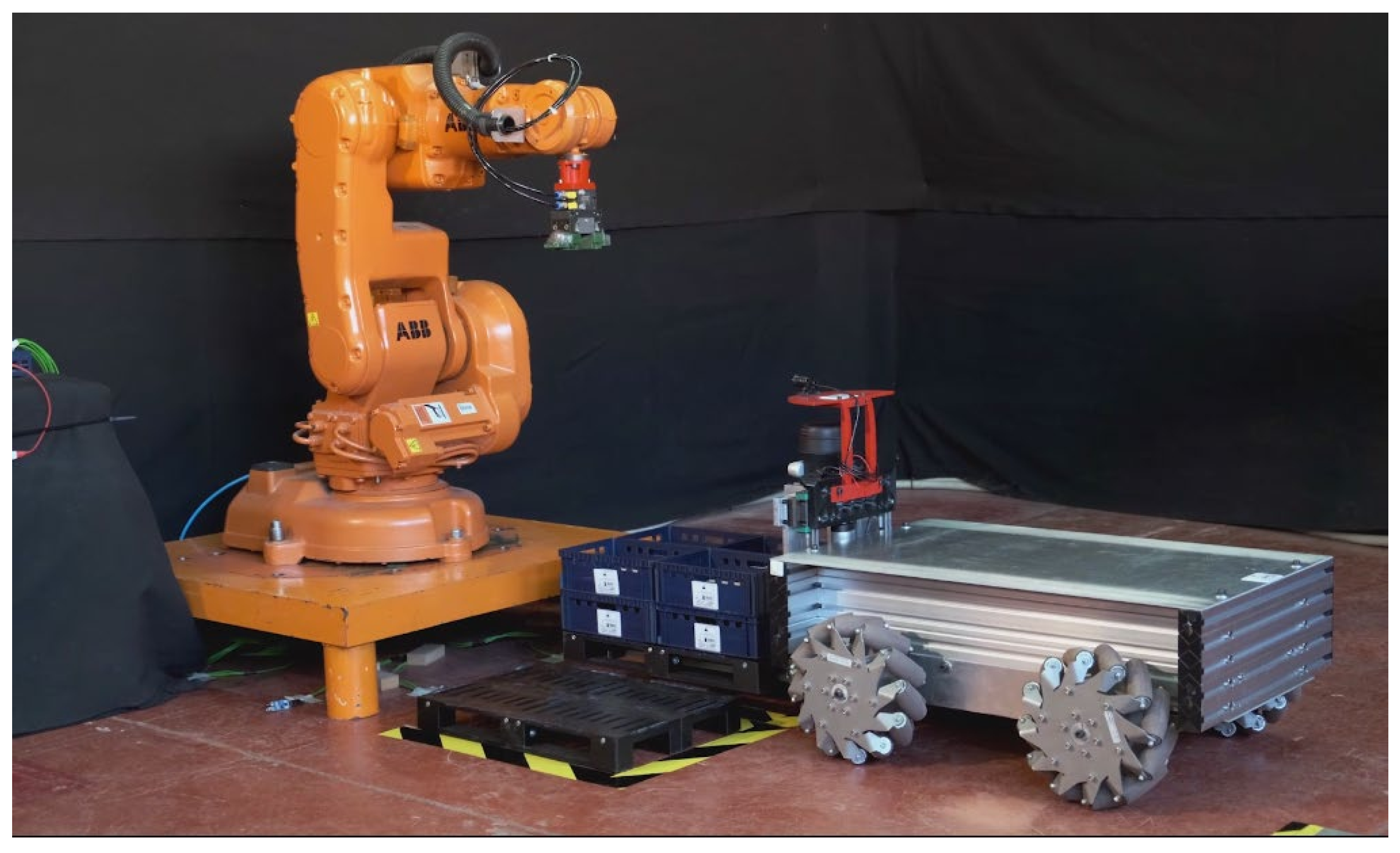
3. Mobile Robot and Industrial Robot Design

As previously mentioned, our solution is the laboratory setup for the automation of the factory floor. Robots are designed to transport EURO pallets and to pick and place objects on the pallet. The mobile robot is designed as a forklift type of a robot to carry EURO pallets with the boxes (crates) used in the meat industry. A common task in this industry is the sorting of crates based on clients’ orders. The task of the industrial robot is to pick crates delivered by a mobile robot and to place them on EURO pallets for different orders. First, we will describe the mobile robot hardware and software for EURO pallet transportation followed by a description of the software for controlling the industrial robot and the design of the tool for crates manipulation.

3.1. Hardware of Mobile Robot

The mobile robot platform, designed in this work, is based on a four wheeled Mecanum drive (Figure 2). The advantage of using Mecanum wheels is the ability to move in any direction without changing orientation. The wheels are actuated by four 100 W BDC motors, powered by Li-ion batteries enabling the robot to operate autonomously for around 16 h. Motors are controlled by motor controllers connected to the main on-board PC. One motor controller can control a pair of brushed DC motors using USB serial, TTL serial, RC or analog inputs. Integrated dual quadrature decoders enable easy, closed-loop speed control system implementation. For this work, a USB serial interface is used to connect the motor controllers with the main computer. The forklift system consists of a linear actuator with a BDC motor and a motor controller. The forklift system is controlled with the set of GPIO signals.
To detect obstacles and navigate through the environment, the mobile robot is equipped with the laser ranging scanner RPLiDAR-A2, and Intel RealSense D415 depth camera. LiDAR and camera sensors are used for both SLAM and path-planning algorithms, whose implementation is described later. The interface between sensors and the main PC is established using the USB 3.0 communication protocol to ensure fast data transfer, without full bandwidth consumption to prevent data loss.
The RealSense depth camera has a standard field of view and high resolution [33], which is well suited for applications that require accuracy, such as 3D scanning and mapping. The standard field of view provides higher quality depth per degree. A relatively high range, up to 10 m, provides good perception of surroundings.
The main PC integrates the LiDAR sensor, depth camera and motor controllers using the ROS framework, which will be explained later. To provide reasonable program execution time, enabling real-time mobile robot control and obstacle avoidance, the main PC has 16 GB DDR4 RAM memory, Ryzen 7 2700U CPU and M.2 NVMe SSD memory.

3.2. Software of Mobile Robot

Mobile robot software consists of several interconnected ROS packages to provide navigation in both known and unknown environments. The main packages used for mapping and navigation are as follows:
  • The RTAB-SLAM ROS package, assigned to provide system (mobile robot) with both map of the environment and robot localization.
  • The TEB ROS package provides a path for a robot to follow, based on a map and odometry from the RTAB-SLAM package.
  • The RoboClaw ROS package enables integration of the motor drivers with the rest of the ROS system.
Additionally, ROS drivers for the LiDAR sensor and RealSense camera are used to provide communication between them and the rest of the system. Figure 3 shows connections between the ROS nodes used on the mobile robot. Mobile robot motion and path planning are provided inside the move_base ROS package. The global_planner node, upon receiving a goal which is described as the desired position and orientation of a robot, outputs a path based on the map created by the RTAB-SLAM node, considering only static obstacles. Obstacle avoidance is provided inside the TEB_planner node, using the Laser Scan topic acquired from the RPLiDAR node (ROS topics are named buses over which nodes exchange messages [34]). The final output of move_base gives the RoboClaw node the desired velocity of the robot base, which is then transformed into corresponding motor speeds. Topics global_costmap and local_costmap, based on the configuration of corresponding nodes, provide distances from obstacles which are not considered safe for a robot to be close to, and path planners adjust trajectories based on those cost maps.
To control the mobile robot platform, the main PC communicates with a motor controller using a dedicated ROS motordriver_ros package. The motordriver_ros package is implemented in Python programming language, enabling easier and faster modifications. The ROS driver package for the motor driver is separated in two parts. The first part communicates with motor controllers using the USB protocol and provides different measurements, such as encoder status, motor current, etc. It also provides a way to set the motor speed to the desired value. The second part of the motordriver_ros driver communicates with the rest of the system, providing information about the robot’s speed and position and waits for a new speed command to be delivered by a path planner.
The four wheeled Mecanum drive can be controlled in two ways. The first way is the standard four wheeled drive, where control and path planning algorithms assume that the mobile platform can move only forward/backward and rotate in place: in other words, with more movement constraints than the Mecanum drive. The control of such a mobile platform is done using the standard approach for controlling a differential drive mobile robot. To provide more flexibility in the mobile robot motion, speed commands provided by the path planner are converted to four separated motor speeds, each for different motor, using a motion model with constraints for mobile platforms with the Mecanum wheels approach described in [35]. Since Mecanum wheels can cause drift that is not sensed by wheel encoders, we had to rely on localization from SLAM. Based on our experience, we decided to use the RTAB-SLAM algorithm [15], as it performs good results for indoor environment accuracy improvements with path loop closure.
In order to evaluate localization from the RTAB-SLAM algorithm and demonstrate the improvement of localization after the loop closure, we prepared a setup to measure coordinates of the mobile robot with an external precise measurement system. We used a motion capture system from the company Vicon, which relied on reflective markers and eight fast infrared cameras. The motion capture system was set up to capture the location of the markers placed on a mobile robot to track its location in the environment (cf. Figure 4).
The mobile robot is programmed to move in the environment in such a way to close the loop after some time. During the motion, the location of the robot is obtained from RTAB-SLAM and the Vicon motion capture system. Figure 5 shows the obtained localization data. We can see that the robot accumulated error while moving in the environment until it closed the loop and corrected significantly the localization estimation. The error after the loop closure was under 1 cm, which was the targeted accuracy for our experiment.

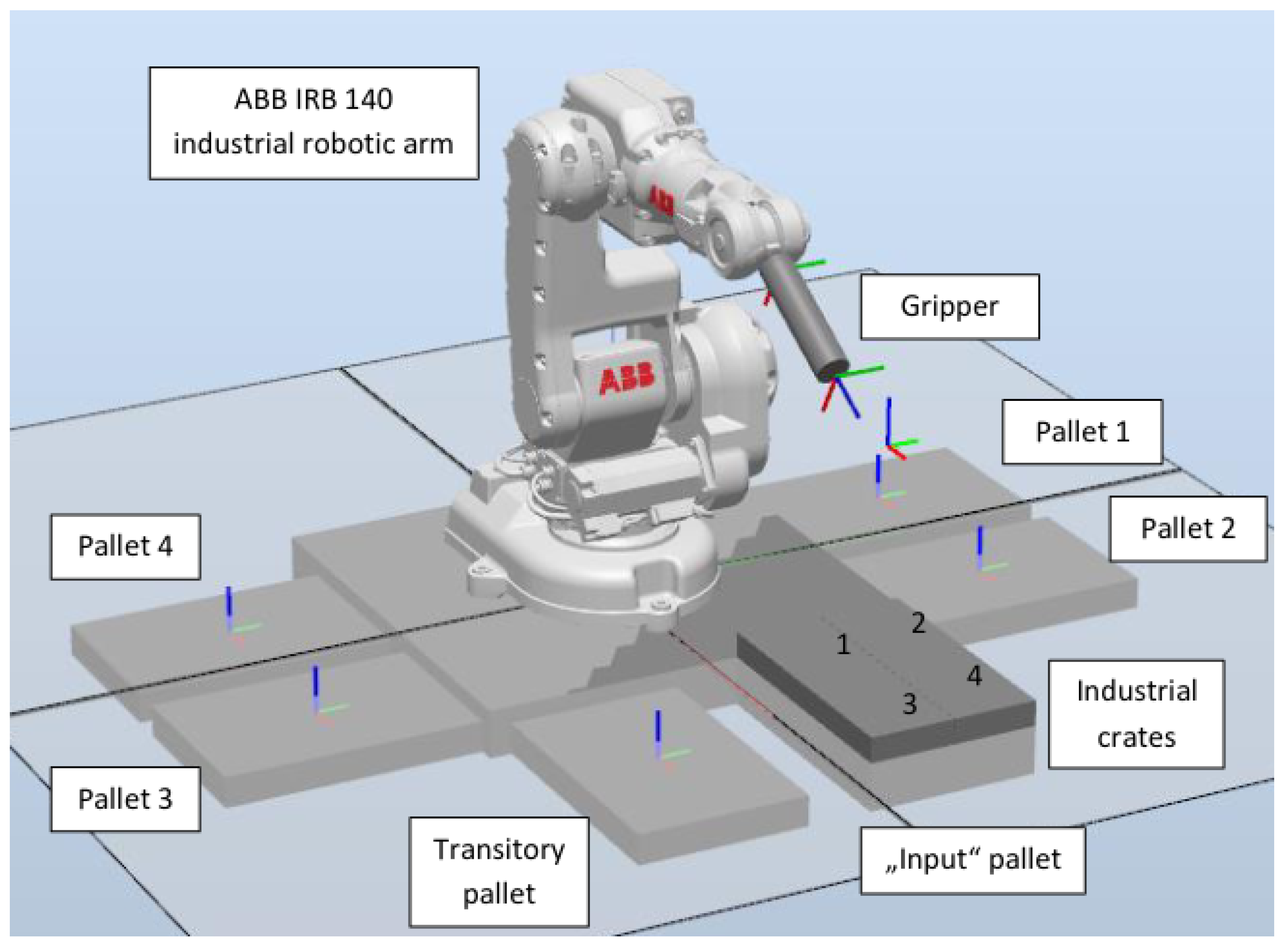
3.3. Industrial Robot and Environment Setup

The industrial robot system consists of the ABB IRB 140 robotic arm [36], dedicated end effector and a corresponding IRC5 controller. The external PC with ROS application is used to instruct the robot arm movements and to integrate the robot arm with the rest of the system. In order for the robot to know where each crate should be placed, an RFID sensor is used to identify each industrial crate. The setup of the industrial robotic arm and its environment was initially designed and simulated in the RobotStudio programming environment [37]. The developed software for simulation was afterwards used to control the real robot.
Within the experiment setup, pallets with crates that the industrial robotic arm needs to sort are placed around the robot (Figure 6). There are six pallets placed around the robot to perform the palletizing task. Four out of six pallets are “output” pallets that should be transferred out after sorting is complete. The “input” pallet with unsorted industrial crates, brought by the mobile robot, is located in front of the robot arm and can contain up to 24 crates. In addition to the “input” pallet, the transitory pallet is set up to temporarily accommodate crates that do not currently have a defined location, as well as crates that have not been successfully identified.
After the spatial arrangement of the station elements was established and the algorithm was confirmed in the simulation environment, the system was created in the real world. The physical setup of the system in the laboratory is shown in Figure 7.
For the task of manipulating industrial crates, a specific gripper was designed and prototyped. It is a two-finger electro-pneumatic gripper. The end effector consists of two claw-like fingers. They are designed in such a manner as to successfully reach within the openings on the sides of industrial crates. If the crates are not accurately positioned on the pallet, to compensate for this misalignment, there is an elastic link between the fingers and the base of the gripper.

3.4. Software of Industrial Robot

An increase in the usage of ROS applications in industrial robotics, and its applications on industrial robotic arms, has contributed to the development of the ROS industrial (ROS-I) platform [38,39]. In addition to the benefits of the standard ROS platform previously mentioned, ROS-I provides us with supplementary tools and capabilities specific to industrial robotic arms. One of the biggest advantages of using the ROS-I platform is the programming of the robotic arm in conventional programming languages, such as Python and C++, instead of the native language of the controller, which is company dependent. The ROS packages used in our work to communicate and control the industrial robot are as follows:
  • abb_driver that enables the communication between personal computer and ABB IRC5 industrial robot controller for robot control. The messages being exchanged contain information about the condition of the robot, such as the position of the robot’s wrists.
  • paletizer package, developed for sorting/palletizing industrial crates, as well as to communicate with the rest of the system, e.g., OPIL, from which it receives the commands for palletization and reports on the state of the task.
  • abb_irb140_unal, the package that provides information about the physical representation of robots, such as URDF and SRDF records.
For controlling the ABB industrial robotic arm, the abb_driver is used [40] (ROS driver for the ABB industrial robots), as the driver is made for specific hardware. The part of the driver located on the industrial controller is written in the programming language RAPID (the native language of the controller), while the part of the driver located on the personal computer is written in C++. The block diagram of communication between two applications/two devices is shown in Figure 8.
Some of the additional features that ROS-I provides in the form of additional packages are an extended set of robotic arm models that the ROS driver can control (abb_experimental package [41]). The experimental package expands the capabilities of the ROS driver and adds the models and parameters of the robotic arms. The most important tool provided using the ROS-I platform is the MoveIt package [42]. The MoveIt package gives us the possibility of creating a functional robot from a CAD model, i.e., generates the required universal robot description format (URDF) and semantic robot description format (SRDF) files to define the parameters of the robotic arm. Additionally, an additional package for a visualization RViz provides us the visualization of 3D models of robots, as well as their movement and coordinate systems.

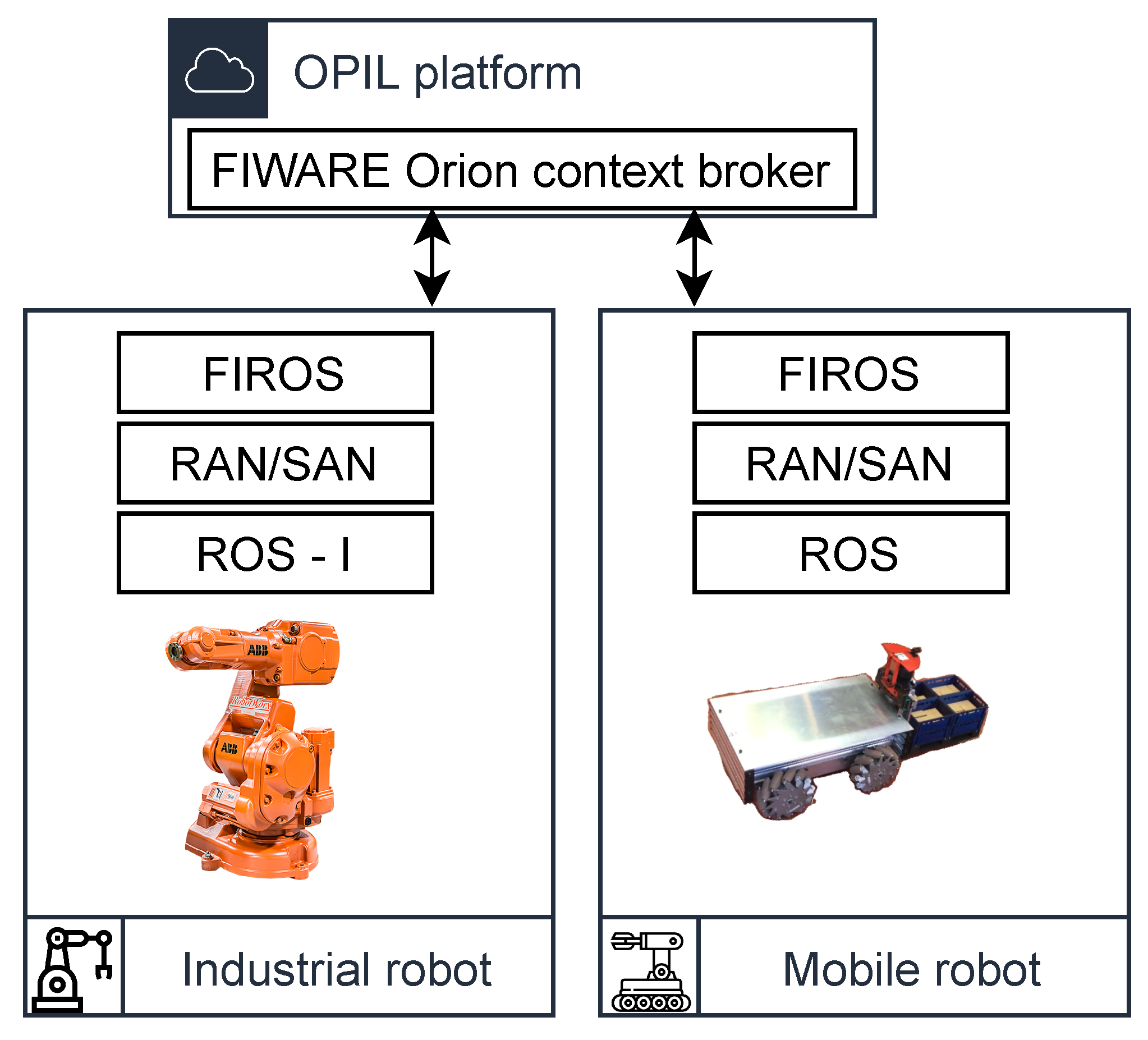
4. System Integration and Experiment

The integration of the system is obtained by the cloud infrastructure with open platform for innovations in logistics (OPIL). OPIL is the open IoT platform that enables digital virtualization, automated scenario setup and communication interface for different factory floor resources. Mobile robots, AGVs, workers, sensors and factory IT infrastructure can be connected through this platform in order to develop and test factory logistic automation. Figure 9 shows the high level organization of integration of our robotic systems with the OPIL platform.
The connection between robots and the cloud is established with the messaging system based on the FIWARE open architecture. The deployment scheme for OPIL-based systems contains the following modules:
  • OPIL server as a cloud infrastructure responsible for hosting the modules, such as task planner, context management, HMI (human–machine interface), SP (sensing and perception).
  • Different nodes in the field, including mobile robots, AGVs, forklifts and sensors.
Generic components of the OPIL server are distributed in a multi-layer architecture, where the bottom layer (IoT nodes layer) components enable interaction with the physical world. This layer may include the following components:
  • Robotic agent nodes (RAN) as nodes responsible for dealing with the physical actors. In the OPIL world, that could be manipulation agents (intended for loading and unloading the goods and products) or moving agents (intended for moving goods or products from one place to another).
  • Human agent nodes (HAN) as nodes in charge of interfacing with humans.
  • Sensor agent node (SAN), i.e., nodes that allow data transfer from various sensing sources to the cloud.
As an illustration of RAN node functionality, let us consider the robot’s motion in dynamic environments. Robot goals can be acquired from servers on the local network, or from the cloud. Setting the robot’s target point starts with reading the current desired position of a robot inside of a facility and publishing that information on an adequate ROS topic. Upon reaching the destination, a task command is issued to a robot, based on readings from a server. The message consists of the position and task command, such as the lifting up or down robot tool. Additionally, the message has the maximum allowed velocity of a robot, desired acceleration rate, etc. Algorithm 1 describes the process executed inside the RAN module.
Similarly, it is necessary to provide the main system with current sensor readings of the robot’s environment. The ROS node tasked with this job is called the sensor agent node (SAN). SAN feeds sensor readings, such as LaserScan received from a LiDAR sensor, to a server. Those readings provide the system with the robot’s current environmental status, based on which the next goal is generated. The new goal is updated over a certain part of the message body generated on server.
Algorithm 1 Goal and task reading.
  • Initialize ROS node;
  • Open connection to a server
  • loop
  •    read current assignment from a server
  •    publish goal to ROS topic
  •    if task command issued then
  •      call ROS service for task execution
  •    end if
  •    send current robot pose to server (odometry readings)
  • end loop
As previously mentioned, abb_driver, written in RAPID and C++ programming languages, was used to control the robotic arm using the ROS-I platform, while the sorting algorithm was written in the Python programming language. The application for palletizing consists of two modules. The sorting/palletizing module (cf. Algorithm 2) and module for communication with OPIL platform (cf. Algorithm 3). The sorting algorithm serves to relocate the industrial crates from the input pallet to the appropriate output pallet specified by the logistics system. The communication algorithm serves to report to the logistics system the current state of the robot arm and obtain the data from it.
The whole process can be summarized as follows: After receiving information from OPIL that the input pallet is present and how many crates are on it, the robot is positioned above the pallet. The robot picks the industrial crate and transfers it to the RFID sensor for identification. Depending on the identification, the robot arm places the crate in a determined position on the corresponding output pallet. When the input pallet is unloaded, the robotic arm returns to the starting position to wait for the next pallet.
Algorithm 2 Sorting/palletizing module realization.
  • Input: pallet information and industrial crates identifiers;
  • Result: Sorts crates onto appropriate pallets depending on their identifier;
  • Initialization
  • loop
  •   goto_position(home)
  •   publish_state (waiting_input_pallet)
  •   wait(input_pallet)
  •   read(input_pallet)
  •   publish_state(input_pallet_arrived) crate on input pallet
  •   for all crate on input pallet do
  •     publish_state(picking_up_crate)
  •     goto_position(input_pallet)
  •     goto_position(crate)
  •     pick_up_crate()
  •     publish_state(crate_picked_up)
  •     goto_position(RFID_scanner)
  •     publish_state(scanning)
  •     pallet, drop_crate_position := read(crate)
  •     publish_state(scanned)
  •     goto_position (pallet)
  •     goto_position(drop_crate_position)
  •     publish_state(dropping_down_crate)
  •     drop_crate()
  •     publish_state(crate_dropped_down)
  •   end for
  • end loop
The algorithm for communication (Algorithm 3) has the role of informing the OPIL system of the state in which the robotic arm is currently found and to take data for palletizing task. The states in which the robot can be found are predefined states depending on the task that it is currently performing. With the help of this module, the robotic arm receives information about the environment around it through a logistics system.
Algorithm 3 Communication with OPIL module.
  • Data: The identifier of the task that the robot performs and data about pallets and industrial crates
  • Result: Reports the robot arm state to the logistics system and communicate sorting data to robot
  • initialization
  • loop
  •    wait(new_message)
  •    robot_state := read(new_message)
  •   switch (robot_state)
  •   case waiting_input_pallet:
  •     wait(input_pallet)
  •   case input_pallet_arrived:
  •     read(input_pallet)
  •     publish(input_pallet)
  •   case picking_up_crate:
  •     pass;
  •   case crate_picked_up:
  •     write(time&date)
  •   case scanning:
  •     wait(crate)
  •   case scanned:
  •     read(crate);
  •     publish(crate)
  •   case dropping_down_crate:
  •     pass;
  •   case crate_dropped_down:
  •     write(time&date)
  •   end switch
  •   reset robot_state
  • end loop

5. Conclusions

In this work, we developed a real-world laboratory setup for research in factory floor automation. The setup consists of two robots: a forklift-type mobile robot with Mecanum wheels and an ABB IRB 140 industrial robot arm. The integration of robots relies on the OPIL system, the open industrial IoT platform that enables the complete digital virtualization of intra-factory logistics automation.
The software and hardware of the mobile robot are described in detail. The important aspect of the mobile robot is the SLAM algorithm used for navigation in the environment. For this purpose, we used RTAB-SLAM and we showed the result of the evaluation of the algorithm on our platform. The precision of the positioning in the laboratory environment after loop closure was under 1 cm, which was satisfactory for our experiment.
During the development of the laboratory setup (hardware and software development), we applied modular architecture which should meet the requirements of the real factory floor automation. The four-wheeled Mecanum drive provides enough freedom for flexible path planning algorithms. The software is developed on top of the ROS architecture, divided in different function blocks, so-called nodes. ROS and ROS-I are open-source frameworks, tailored for robotics development, making this approach independent from a particular robotic platform. This enables easy integration with the OPIL cloud platform through dedicated modules. The use-case experiment showed successful integration and robotic service orchestrations with cloud service, which manages and distributes tasks on the factory floor. It receives information from sensors and robots on the current status of the factory floor, and based on the status and requirements, it issues commands to robots. The developed system is, thus, proven to be useful for the development of different solutions for factory floor automation and for the validation of research in this domain.

Author Contributions

Conceptualization, D.M. and M.R.; methodology, M.R.; software, D.M., L.M. and A.Č.; validation, M.R., L.M. and A.Č.; resources, T.B. and A.G.; writing—original draft preparation, D.M., M.R., L.M., A.Č. and T.B.; writing—review and editing, D.M. and M.R; visualization, D.M., L.M. and A.Č.; supervision, M.R.; project administration, M.R.; funding acquisition, M.R. and A.G. All authors have read and agreed to the published version of the manuscript.

Funding

This research received no external funding.

Acknowledgments

The authors would like to thank to their students for participating in preparing and running experiments.

Conflicts of Interest

The authors declare no conflict of interest.

References

  1. Huang, S.; Dissanayake, G. Robot Localization: An Introduction. In Wiley Encyclopedia of Electrical and Electronics Engineering; John Wiley & Sons, Ltd.: Hoboken, NJ, USA, 2016; pp. 1–10. [Google Scholar] [CrossRef]
  2. Wong, C.C.; Yeh, L.Y.; Liu, C.C.; Tsai, C.Y.; Aoyama, H. Manipulation Planning for Object Re-Orientation Based on Semantic Segmentation Keypoint Detection. Sensors 2021, 21, 2280. [Google Scholar] [CrossRef]
  3. Rezende, A.M.; Gonçalves, V.M.; Pimenta, L.C. Safe coordination of robots in cyclic paths. ISA Trans. 2021, 109, 126–140. [Google Scholar] [CrossRef]
  4. Pinkam, N.; Bonnet, F.; Chong, N.Y. Robot collaboration in warehouse. In Proceedings of the 2016 16th International Conference on Control, Automation and Systems (ICCAS), Gyeongju, Korea, 16–19 October 2016; pp. 269–272. [Google Scholar] [CrossRef]
  5. Pires, J.N.; Costa, J.; d’Souza, F. Development of a solution for adding a collaborative robot to an industrial AGV. Ind. Robot. 2020, 47, 723–735. [Google Scholar] [CrossRef]
  6. Kaliappan, S.; Lokesh, J.; Mahaneesh, P.; Siva, M. Mechanical Design and Analysis of AGV for Cost Reduction of Material Handling in Automobile Industries. Int. Res. J. Automot. Technol. 2018, 1, 1–7. [Google Scholar]
  7. Doroftei, I.; Grosu, V.; Spinu, V. Omnidirectional Mobile Robot—Design and Implementation. In Bioinspiration and Robotics; Habib, M.K., Ed.; IntechOpen: Rijeka, Croatia, 2007; Chapter 29. [Google Scholar] [CrossRef] [Green Version]
  8. Diegel, O.; Badve, A.; Bright, G.; Potgieter, J.; Tlale, S. Improved Mecanum Wheel Design for Omni-directional Robots. In Proceedings of the Australasian Conference on Robotics and Automation, Wellington, New Zealand, 3–5 December 2012. [Google Scholar]
  9. Saha, S.K.; Angeles, J.; Darcovich, J. The design of kinematically isotropic rolling robots with omnidirectional wheels. Mech. Mach. Theory 1995, 30, 1127–1137. [Google Scholar] [CrossRef]
  10. Grisetti, G.; Stachniss, C.; Burgard, W. Improved Techniques for Grid Mapping With Rao-Blackwellized Particle Filters. IEEE Trans. Robot. 2007, 23, 34–46. [Google Scholar] [CrossRef] [Green Version]
  11. Kohlbrecher, S.; von Stryk, O.; Meyer, J.; Klingauf, U. A flexible and scalable SLAM system with full 3D motion estimation. In Proceedings of the 2011 IEEE International Symposium on Safety, Security, and Rescue Robotics, Kyoto, Japan, 1–5 November 2011; pp. 155–160. [Google Scholar] [CrossRef] [Green Version]
  12. Newman, P.; Ho, K. SLAM-loop closing with visually salient features. In Proceedings of the 2005 IEEE International Conference on Robotics and Automation, Barcelona, Spain, 18–22 April 2005; pp. 635–642. [Google Scholar]
  13. Mur-Artal, R.; Tardós, J.D. ORB-SLAM2: An Open-Source SLAM System for Monocular, Stereo, and RGB-D Cameras. IEEE Trans. Robot. 2017, 33, 1255–1262. [Google Scholar] [CrossRef] [Green Version]
  14. Galvez-López, D.; Tardos, J.D. Bags of Binary Words for Fast Place Recognition in Image Sequences. IEEE Trans. Robot. 2012, 28, 1188–1197. [Google Scholar] [CrossRef]
  15. Labbé, M.; Michaud, F. RTAB-Map as an open-source lidar and visual simultaneous localization and mapping library for large-scale and long-term online operation. J. Field Robot. 2019, 36, 416–446. [Google Scholar] [CrossRef]
  16. Fox, D.; Burgard, W.; Thrun, S. The dynamic window approach to collision avoidance. IEEE Robot. Autom. Mag. 1997, 4, 23–33. [Google Scholar] [CrossRef] [Green Version]
  17. Quinlan, S.; Khatib, O. Elastic bands: Connecting path planning and control. In Proceedings of the IEEE International Conference on Robotics and Automation, Atlanta, GA, USA, 2–6 May 1993; Volume 2, pp. 802–807. [Google Scholar] [CrossRef]
  18. Rösmann, C.; Hoffmann, F.; Bertram, T. Timed-Elastic-Bands for Time-Optimal Point-to-Point Nonlinear Model Predictive Control. In Proceedings of the 2015 European Control Conference (ECC), Linz, Austria, 15–17 July 2015; pp. 3352–3357. [Google Scholar] [CrossRef]
  19. Blanes, C.; Mellado, M.; Beltran, P. Novel Additive Manufacturing Pneumatic Actuators and Mechanisms for Food Handling Grippers. Actuators 2014, 3, 205–225. [Google Scholar] [CrossRef] [Green Version]
  20. Mangan, E.V.; Kingsley, D.A.; Quinn, R.D.; Sutton, G.P.; Mansour, J.M.; Chiel, H.J. A biologically inspired gripping device. Ind. Robot. Int. J. 2005, 32, 49–54. [Google Scholar] [CrossRef]
  21. Muscato, G.; Prestifilippo, M.; Abbate, N.; Rizzuto, I. A prototype of an orange picking robot: Past history, the new robot and experimental results. Ind. Robot. Int. J. 2005, 32, 128–138. [Google Scholar] [CrossRef]
  22. Ali, M.H.; Zhanabayev, A.; Khamzhin, S.; Mussin, K. Biologically Inspired Gripper Based on the Fin Ray Effect. In Proceedings of the 2019 5th International Conference on Control, Automation and Robotics (ICCAR), Beijing, China, 19–22 April 2019; pp. 865–869. [Google Scholar] [CrossRef]
  23. Inaba, M. Remote-brained robotics: Interfacing ai with real world behaviors. In Proceedings of the 6th International Symposium of Robotics Research, Puerto Varas, Chile, 11–14 December 2017; pp. 335–344. [Google Scholar]
  24. Kamei, K.; Nishio, S.; Hagita, N.; Sato, M. Cloud networked robotics. IEEE Netw. 2012, 26, 28–34. [Google Scholar] [CrossRef]
  25. Sanfeliu, A.; Hagita, N.; Saffiotti, A. Network robot systems. Robot. Auton. Syst. 2008, 56, 793–797. [Google Scholar] [CrossRef] [Green Version]
  26. Honkote, V.; Ghosh, D.; Narayanan, K.; Gupta, A.; Srinivasan, A. Design and Integration of a Distributed, Autonomous and Collaborative Multi-Robot System for Exploration in Unknown Environments. In Proceedings of the 2020 IEEE/SICE International Symposium on System Integration (SII), Honolulu, HI, USA, 12–15 January 2020; pp. 1232–1237. [Google Scholar] [CrossRef]
  27. Bresson, G.; Alsayed, Z.; Yu, L.; Glaser, S. Simultaneous localization and mapping: A survey of current trends in autonomous driving. IEEE Trans. Intell. Veh. 2017, 2, 194–220. [Google Scholar] [CrossRef] [Green Version]
  28. Saha, O.; Dasgupta, P. A Comprehensive Survey of Recent Trends in Cloud Robotics Architectures and Applications. Robotics 2018, 7, 47. [Google Scholar] [CrossRef] [Green Version]
  29. Cardarelli, E.; Digani, V.; Sabattini, L.; Secchi, C.; Fantuzzi, C. Cooperative cloud robotics architecture for the coordination of multi-AGV systems in industrial warehouses. Mechatronics 2017, 45, 1–13. [Google Scholar] [CrossRef]
  30. Waibel, M.; Beetz, M.; Civera, J.; d’Andrea, R.; Elfring, J.; Galvez-Lopez, D.; Haussermann, K.; Janssen, R.; Montiel, J.; Perzylo, A.; et al. A world wide web for robots. IEEE Robot. Autom. Mag. 2011, 18, 69–82. [Google Scholar] [CrossRef] [Green Version]
  31. Arumugam, R.; Enti, V.R.; Liu, B.; Wu, X.; Baskaran, K.; Kong, F.F.; Kumar, A.S.; Kang, D.M.; Kit, G.W. DAvinCi: A cloud computing framework for service robots. In Proceedings of the 2010 IEEE International Conference on Robotics and Automation, Anchorage, AK, USA, 3–8 May 2010; pp. 3084–3089. [Google Scholar] [CrossRef]
  32. Riazuelo, L.; Civera, J.; Montiel, J.M.M. C2TAM: A Cloud framework for cooperative tracking and mapping. Robot. Auton. Syst. 2014, 62, 401–413. [Google Scholar] [CrossRef] [Green Version]
  33. Carfagni, M.; Furferi, R.; Governi, L.; Santarelli, C.; Servi, M.; Uccheddu, F.; Volpe, Y. Metrological and Critical Characterization of the Intel D415 Stereo Depth Camera. Sensors 2019, 19, 489. [Google Scholar] [CrossRef] [Green Version]
  34. ROS Documentation Website. 2019. Available online: http://wiki.ros.org/Topics (accessed on 12 October 2021).
  35. Röhrig, C.; Heß, D.; Künemund, F. Motion controller design for a mecanum wheeled mobile manipulator. In Proceedings of the 2017 IEEE Conference on Control Technology and Applications (CCTA), Kohala Coast, HI, USA, 27–30 August 2017; pp. 444–449. [Google Scholar] [CrossRef]
  36. Almaged, M. Forward and Inverse Kinematic Analysis and Validation of the ABB IRB 140 Industrial Robot. Int. J. Electron. Mech. Mechatron. Eng. 2017, 7, 1383–1401. [Google Scholar] [CrossRef]
  37. Holubek, R.; Delgado Sobrino, D.R.; Košťál, P.; Ružarovský, R. Offline Programming of an ABB Robot Using Imported CAD Models in the RobotStudio Software Environment. Appl. Mech. Mater. 2014, 693, 62–67. [Google Scholar] [CrossRef]
  38. Zhang, L.; Merrifield, R.; Deguet, A.; Yang, G.Z. Powering the world’s robots-10 years of ROS. Sci. Robot. 2017, 2, eaar1868. [Google Scholar] [CrossRef] [Green Version]
  39. Chan, M.L.; Hvass, P. ROS-Industrial: Expanding Industrial Application Capabilities. J. Robot. Soc. Jpn. 2017, 35, 307–310. [Google Scholar] [CrossRef]
  40. Venator, E.; Zoss, J.; Edwards, S. ABB_DRIVER—ROS Wiki. 2021. Available online: http://wiki.ros.org/abb_driver (accessed on 12 October 2021).
  41. Edwards, S. ABB_Experimental—ROS Wiki. Available online: http://wiki.ros.org/abb_experimental (accessed on 12 October 2021).
  42. Chitta, S.; Sucan, I.; Cousins, S. MoveIt! [ROS Topics]. IEEE Robot. Autom. Mag. 2012, 19, 18–19. [Google Scholar] [CrossRef]
Figure 1. ABB IRB 140 robot and mobile four wheel drive robot in laboratory.
Applsci 12 01228 g001
Figure 2. The forklift-type mobile robot with Mecanum wheel carrying EURO pallet with eight crates.
Applsci 12 01228 g002
Figure 3. Organization of ROS nodes in mobile robot ROS network connections.
Applsci 12 01228 g003
Figure 4. Experimental setup with Vicon motion capture and reflective markers for evaluation RTAB-SLAM localization in the indoor environment.
Applsci 12 01228 g004
Figure 5. Comparison of RTAB-SLAM localization against trajectory obtained with motion capture system.
Applsci 12 01228 g005
Figure 6. System setup and the layout in the RobotStudio software environment.
Applsci 12 01228 g006
Figure 7. Setup of an industrial robot station with surrounding EURO pallets in the laboratory.
Applsci 12 01228 g007
Figure 8. Block diagram for controlling the ABB IRB 140 robot arm from the ROS application.
Applsci 12 01228 g008
Figure 9. System architecture of robots integration with OPIL platform.
Applsci 12 01228 g009
Publisher’s Note: MDPI stays neutral with regard to jurisdictional claims in published maps and institutional affiliations.

