Article

BIM-Based Maintenance Data Processing Mechanism through COBie Standard Development for Port Facility

BIM Research Cluster, Department of Future & Smart Construction Research, Korea Institute of Civil Engineering and Building Technology, Goyang-si 10223, Korea
*
Author to whom correspondence should be addressed.
Appl. Sci. 2022, 12(3), 1304; https://doi.org/10.3390/app12031304
Submission received: 12 December 2021 / Revised: 23 January 2022 / Accepted: 24 January 2022 / Published: 26 January 2022

Abstract

:
In the AECO field, there have been many efforts to transform the design, construction, and maintenance methods that have been carried out in the traditional way based on document-based data into digital ones. BIM makes it possible for the information necessary for the entire construction process to be transformed into a language that computers can understand. In the field of architecture, BIM has been actively used throughout the entire construction life cycle through steady research since the 2000s, while COBie was developed in order to deliver information generated in the design and construction phase to the maintenance phase based on the BIM environment. In the field of infrastructure, however, digital data-based maintenance information management has not been actively studied. In particular, in the case of a port, once a facility is built, it has to be maintained for a longer period than other facilities, so facility maintenance is of utmost importance. Therefore, this study applied COBie, which is being used in the architecture field (building), to the port field. To this end, the COBie standard format in the port field was developed based on the port facility object breakdown structure and property breakdown structure. The port COBie developed through this study is included when the BIM model is converted to the IFC model so that facility management can be performed through the IFC-based viewer in the future. The port COBie schema developed in this study can be expanded to other fields such as roads and bridges in the future.

1. Introduction

In recent years, as part of the digitalization of Social Overhead Capital (SOC), the port sector is pursuing digital innovation. Unlike other facilities, port facilities need to be managed and operated for a long time once they are built, and since they are in contact with the sea, maintenance is very essential and depends on external factors. However, the port-related maintenance system still focuses on data collection, storage, and management, and it is insufficient to establish an environment that can be used or analyzed for maintenance work. In addition, port-related maintenance data exists in the form of a silo that is built once, and there is a problem that data cannot be shared due to lack of connection with other systems. In particular, when maintenance information is updated, the provision of a related system that can be replaced quickly is insufficient. In addition, port facilities prone to data loss need to be converted into BIM-based digital data for facility maintenance [1]. Therefore, this study intends to establish a framework that allows port maintenance information to be exchanged, shared, and utilized among systems, subjects and functions within the BIM environment. To this end, we developed port COBie, a standard format for port BIM-based maintenance data exchange and describe how it is processed in the process of generating, converting, transmitting and utilizing COBie data through overseas commercial BIM S/W. Through this, we develop a processing mechanism that allows maintenance information to be exchanged between the port maintenance system and the platform on the port BIM platform and to check the maintenance information for each facility and member through the port BIM viewer.
In the future, this study will be able to be utilized as a common method of exchanging and processing maintenance data if the BIM platform is developed not only for other port facilities, but also for objects requiring maintenance such as roads and bridges.

2. Literature Review Focusing on the Use of COBie Data from Architecture to Civil Engineering

Facility management requires considerable information generated in the design and construction phases. Ideally, the relevant information in the facility management phase should be reviewed and collected in advance during the design and construction phases [2], and it should be automatically linked to the maintenance process for use. However, most information needed for facility management is re-entered into the facility management system according to the existing 2D drawings and specifications. This has reduced the efficiency of information management in facility management [3]. However, following the introduction of building information modeling (BIM) in the mid-2000s, an environment for integrated management (i.e., including the design, construction, and operation phases) has been established. In the BIM-based environment, the information required for the facility management phase is also considered when generating BIM information in the design and construction phases. However, despite its many advantages and possibilities, the use of BIM information in the facility management phase remains limited, in that this information is not fully linked with the existing facility management system [4,5]. To overcome this, a facility management system that directly imports and utilizes BIM-based design information has been developed overseas, and researchers have sought to establish a system to deliver information generated throughout the design and construction phases to the facility management phase [6]. One such study was conducted by government agencies in charge of issuing orders for major infrastructure projects in the United States; as a result, the data exchange format, Construction Operation Building Information Exchange (COBie), was developed. Recently, in South Korea, basic research was conducted on COBie, including analysis of user requirements for the implementation of COBie in the construction field, analysis of information collection systems in the design and construction phases, development of BIM input standards considering the maintenance, and development of BIM guidelines for infrastructure maintenance in the civil engineering field. Won et al. (2013) conducted research related to domestic and foreign BIM-based facility management, suggesting that it was more important to generate BIM data for design and construction using information required from a maintenance perspective than to use the BIM data for actual BIM-based maintenance [7]. Motawa and Almarshad (2013) developed a web-based building maintenance system linking a BIM module and case-based reasoning knowledge management module, and they used the table of contents in the operation and management contract as a classification system for storing and utilizing information [8]. Gerber et al. (2012) conducted a survey on the extent of BIM-based facility management utilization in the industry [9], and they presented the following ten BIM application fields (from the perspective of facility management): building member location tracking, real-time data access, visualization and sales, maintainability improvement, digital asset management, space management, planning and feasibility reviewing for small-scale building facility improvement, disaster management, energy management, and education and training [9]. Lee et al. (2012) compared the COBie methodology (a facility management request information collection system) with the current facility management information collection system in South Korea, in terms of information generation, collection, and utilization; they discussed ways to improve the information collection system [10]. An et al. (2012) conducted a comparative analysis of the COBie-required information for one domestic university facility management system and one office building maintenance system, suggesting a significant consistency between the COBie-required information and the maintenance-system-required information derived through experts; furthermore, case analysis of BIM-based maintenance research has recently begun in the civil engineering field [6]. Moon et al. (2011) presented the feasibility of a BIM application for maintenance, by constructing a 3D model of a bridge structure and implementing a function to store and retrieve maintenance data for the 3D members [11]. Kim et al. (2012) described how the identification of an application model, the standardization of the maintenance information system, and the reorganization of the system were prerequisites for applying BIM technology to maintenance in the civil engineering field [12]. Seo et al. (2017) conducted a study into the generation of COBie-based railway track maintenance documentation [13]. Moon et al. (2020) studied the development of a BIM-based platform to manage information generated from port facilities, in terms of life cycles [14]. However, among the civil engineering fields, relatively few attempts have been made to apply BIM to ports, when compared to other fields such as roads and railroads. Very few new projects are associated with ports (as compared to other projects); furthermore, once a facility is built, it tends to be used for a long time. Therefore, the maintenance of port facilities is particularly important and essential (Moon et al., 2020) [14,15]; however, such maintenance is manually performed by humans, and the systems and information required for maintenance have not been standardized either. As a result, problems have arisen when linking the operation system with those previously developed. Therefore, this study aims to build a technology that allows port maintenance information to be shared and utilized via exchanges among the systems, subjects, and functions within the port BIM platform. In this study, a port BIM-based maintenance data standard format, port COBie, is developed; then, a data exchange process for port COBie is developed by analyzing the processes of COBie data creation, conversion, implementation, and management, using existing research and commercial BIM software. This suggests a method for exchanging maintenance information between the port maintenance system and port BIM platform, thereby allowing the maintenance information for each facility and member to be verified through the port BIM viewer.
Section 3 analyzes the concepts and schematic structure of the existing COBie, as well as the COBie system currently in commercial use at home and abroad; this section will also detail how to create and use COBie data and the data processing mechanism. Based on the analysis of the existing COBie, Section 3 proposes a COBie schema and spreadsheet that can be used in the port sector. Section 4 implements a system that can utilize port COBie data in the BIM environment, using the port COBie format proposed in Section 3.

3. Port COBie Schema for Digital Data-Based Facility Management

3.1. What Is the Existing COBie?

This section develops a COBie schema for port facility management. COBie stands for “Construction Operation Building Information Exchange,” and it is designed to operate construction facilities. In the design phase, facility management information (e.g., general facility information and spatial information) is generated [16]. This information is transferred to the facility management phase via drawings, specifications, or in the form of documents such as maintenance plans and guidelines. Most of the facility information submitted by contractors is based upon data prepared via specialized companies, manufacturers, and suppliers directly involved in building or delivering equipment or systems. However, for the facility manager to utilize these data in the facility management system, it is necessary to directly identify the data generated in the design and construction phases that are required for facility management, as well as to input these data as the initial data of the facility management system [16]. Although BIM is used to solve these problems, its utilization is limited by the excessive cost of introducing software or developing a BIM-based facility management system [17]. Therefore, an International Foundation Class (IFC)-based method to easily apply BIM data in the facility management phase is urgently required [18]; this has led to the COBie data exchange system, which was developed by governmental agencies in charge of issuing orders for major infrastructure projects in the United States [17].
COBie is a data exchange format developed by the Corps of Engineers to facilitate the utilization of BIM data in the IFC; it has been developed up to Ver. 2.4. Although Ver. 2.5 for IFC4×3 has been released, Ver. 2.4 is more commonly used [19]. COBie is an IFC standard that supports the direct exchange of information between software and the spreadsheets used to collect necessary data [16]. As shown in Figure 1, the information required for COBie is not collected by reproducing or re-entering facility management information following the completion of construction; rather, the data generated by the participants in the representative projects of each process (e.g., the design, construction, and operation phases) are used directly, without having to wait until the end of the project. This is a process-oriented representation method in which information producers directly contribute at the time of creation; with this, it is possible to reduce the cost, procurement, and management difficulties that arise in the final post-construction phases of the project, whilst also generating and storing as-built drawings and transferring them for facility management [17].
The COBie system used in the architecture comprises 18 worksheets (“Contact,” “Facility,” “Floor,” “Space,” “Zone,” “Type,” “Component,” “System,” “Spare,” “Resource,” “Job,” “Document,” “Attribute,” “Coordinate,” “Connection,” “Issue,” “Impact,” and “Assembly”) and has a structure as shown in Figure 2. Each worksheet in Figure 2 represents a type of database; these are structured to hold a variety of data, as shown in Figure 3.
The COBie specification developed alongside COBie designates specific milestones that require data input for each phase of a project, as shown in Table 1; furthermore, it defines who should input what information.
Because the fundamental purpose of COBie is to efficiently obtain information (relevant to facility management) generated in the design and construction phases, an Excel-based spreadsheet that can be easily accessed and handled by anyone is often used [20]. This allows users to manually input information into the spreadsheet according to the manual; furthermore, COBie data have until recently been mostly generated by BIM software. There are two ways to generate COBie data using BIM software: (1) export an IFC or IFCXML file from BIM software, convert it to an XML file, and then convert it back to an Excel file (as shown in Figure 4); (2) create a COBie file directly from the BIM software, in which case a file conversion module may be installed as a plug-in for utilization, depending on the BIM software. Systems that support this method include Revit by Autodesk, Onuma System by Onuma, and Tokmo Production System by TOKMO, with continuous compatibility tests with the COBie system being conducted through the COBie challenge.

3.2. Commercial COBie System Analysis

Table 2 shows the commercial systems that handle COBie data. Because most commercial systems that use COBie data require data for specific phases, it is difficult to continuously perform maintenance upon a single platform throughout the entire life cycle of planning, design, construction, and operation. It is likewise difficult to intuitively understand how maintenance is to be performed for each member in the BIM model, because most systems focus on generating COBie data and providing this data in the form of a spreadsheet (Yalcinkaya et al., 2019). In addition, most commercial systems generate COBie data, with representative examples including dRofus, Onuma systems, AECOsim, and Revit. Although systems for internally setting and generating COBie data have been established in these systems, a system that facilitates direct utilization of COBie data for maintenance has not yet been established. Commercial systems such as Solibri, Viewpoints (4 Project), and Ecodomus not only generate COBie data but also establish systems to check the COBie data for each member, for management use. However, an additional process is required to visualize data within the system. Following previous research, this study intends to develop a port COBie schema based on COBie 2.4 and construct a system that can convert COBie data into an IFC model by inputting them into the BIM environment.

3.3. Development of Port COBie Schema

3.3.1. Background References for Developing Port COBie Schema

In this study, a BIM-based COBie data standard suitable for the port field is developed through the processes of COBie standard analysis, maintenance data analysis, development methodology establishment, COBie data model development, and COBie data verification. COBie standard analysis is an essential process for developing the port COBie schema. Maintenance research has been consistently performed in the construction field, and there is sufficient research related to COBie. The basis for COBie data inputting into the BIM environment has also been prepared. However, very little research has been performed upon facility management in the port sector, when compared with the construction field; furthermore, no maintenance exchange standard has been developed for COBie. Therefore, to develop the port COBie schema, we analyzed the existing literature and conventional systems developed for maintenance. The first reference for developing the port COBie schema was the original COBie schema (Version 2.4) used in the existing building facilities. The second and third references were the object breakdown structure (OBS) and property breakdown structure (PBS) of port facilities (Figure 5). In the case of the existing COBie schema, since it is an international standard maintenance data exchange standard format in the field of architecture, based on it, it was intended to aim for an international standard. In addition, the OBS and PBS of the port facility were applied to the port COBie schema, which means what the purpose of port COBie schema was based on BIM. The port facility’s OBS follows the international standard ISO12006-3. The following figure shows the composition and structure of the port object classification system applied to the development of the port COBie schema. The port facility’s PBS was referred to in order to define which properties are required in each sheet of the port COBie schema.

3.3.2. Port COBie Schema Developing Process

Port maintenance data analysis describes the process of deriving the components of port COBie. The component derivation consists of four steps: classification, categorization, generalization, and normalization. In the listing step, we derived all elements required for port maintenance through analysis of the existing literature or maintenance systems. We referred to existing port facilities for the maintenance history, decision-making information, and property classification system. Within the system, the components required for port COBie were listed by referring to LandXML, CityGML, and InfraGML. Using the results of the listing step, the question of whether to include certain components in COBie and to reflect it in each COBie worksheet were decided via categorization. Figure 5 depicts the process of this step; in it, we decided whether to include something in COBie or not, according to assessments of the degree, performance, and risk, as well as the properties of each classification obtained via listing.
In generalization, the COBie worksheets were organized according to the required, optional, and maintenance properties. According to the COBie structure, each sheet was allocated several properties, and the properties were classified into “required,” “reference to other sheets,” “external reference,” and “optional.” Therefore, it was necessary to determine whether newly created sheets in Port COBie or newly added properties in existing sheets were required or optional. Figure 6 shows the two-step categorization process.
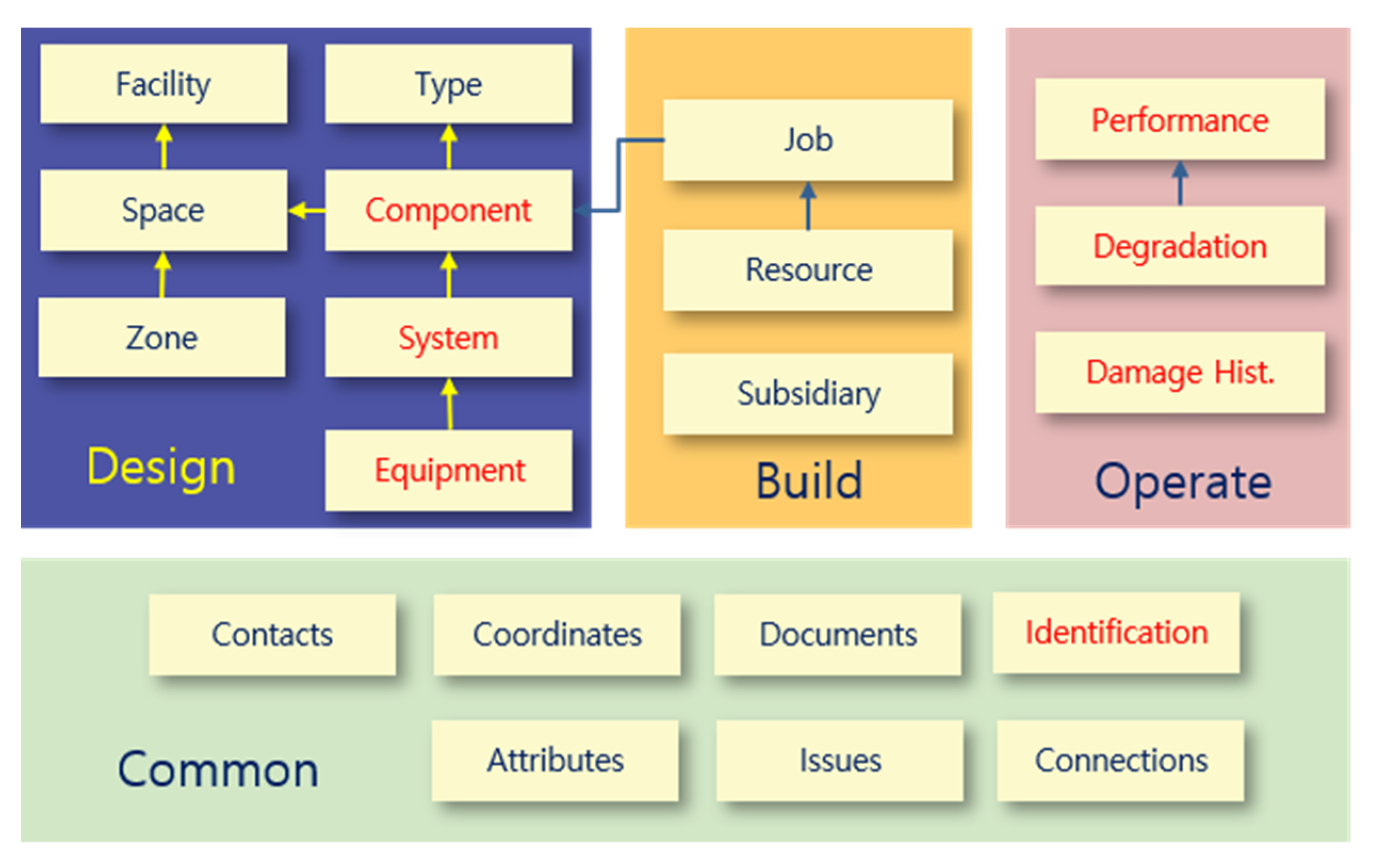
In the final normalization step, the selected COBie components were determined by examining the adequacy of each property and the errors in the results of generalization. Figure 7 shows the composition of the port COBie worksheet selected through classification, categorization, generalization, and normalization. Port facility maintenance information can be defined in the design, construction, and trial operation phases according to the project characteristics and the client’s requirements; however, the maintenance data generation undertaken directly or indirectly in the operation phase is also important (Moon et al., 2021). Although regular inspections and precise safety diagnoses are performed periodically for port maintenance (according to South Korean law), the method is unsystematic with the inputs generated non-digitally, hindering management. Therefore, the operation part (absent from existing COBie systems in the construction field) was newly added to the port COBie system. Figure 8 shows the port COBie worksheet configuration applied in this study. In the design phase, “Floor” in the construction COBie was deleted, and “Equipment” and “System” were added alongside “Facility,” “Space,” “Zone,” and “Component.” “Subsidiary” (additional) provides information on auxiliary facilities; it was added into the construction phase. In the newly added operation phase, the “Performance,” “Degradation,” and “Damage History” tabs were added to create and input the information generated by each subject in the operation phase. This reflected information such as port facility history management, deterioration prediction, and performance analysis. Furthermore, breakdown and identification were added to the common properties, to provide a classification and recognition system for port facilities. The port BIM COBie schema was configured as described below. Using the developed port schema, the next section develops an environment that facilitates the direct input of COBie data into the BIM environment.

4. Implementation

4.1. Implementation Process for COBie Data Input System Based on Port COBie Schema

The purpose of this section is to develop a system that allows the developed port COBie to be inputted as digitized information in the BIM environment. For the purpose of developing the system, the data processing mechanism of the existing commercial COBie systems analyzed in Section 2 was referred to. Since COBie has not been applied to a port, all commercial systems included in the analysis were from the architectural field. Seven COBie systems were included in our analysis. The commercial COBie systems allow data to be inputted at each phase rather than throughout the entire construction life cycle (planning, design, construction, and operation). For instance, dRofus allows the COBie data required for future operation to be inputted in the planning phase of the project; likewise, AECOsim Building Designer and Revit, cBIM, and AiM allow the input of COBie data in the design, construction, and maintenance operation phases, respectively. Onuman System and EcoDomus System allow COBie data to be input throughout all phases of the project. Each system has a different COBie data processing method. However, the COBie data generation and processing procedures are largely classified into three categories: (1) methods that bring COBie data into the system, by installing the plug-in service of the system in a BIM environment such as Revit; systems such as dRofus, Onuma System, and EcoDomous use this method (Table 2). (2) Methods of importing the BIM model (converted from BIM software into an IFC file (the standard format for open BIM)) into the system and creating COBie data through the system process; AECOsim Building Designer uses this method. (3) Methods of manually entering data into a COBie spreadsheet, converting it to XML format, and importing it into the system; early COBie systems used this method, but it has since become unpopular. Commercial COBie systems have their own procedures; however, this requires data to be imported from the BIM model to the specific system. Therefore, this study intends to create an environment in which COBie data can be directly inputted, without requiring other intermediary systems in the BIM environment. In order to supplement the limitation of the existing systems, this study intends to implement the port COBie system by converting the COBie data into the data of the BIM model in the BIM environment. Since BIM data are generally built in the BIM environment in the form of parameters, the port COBie data are also stored in the BIM environment in the form of parameters. In addition, by analyzing the attributes of each port COBie sheet, the part that automatically receives data in connection with the parameters of the existing BIM model and the part where the user must directly input data for port facility maintenance are distinguished. The port COBie schema implementation system is developed through visual programming, Dynamo. Dynamo is also used to perform actual data input simulation of the developed system. The following Figure 9 includes the system implementation procedure and simulation procedure as the system implementation methodology of this study.

4.2. Development of Port COBie System Focusing on Revit Environment

For port facilities, it is important to transfer and utilize the information prepared from the design and construction phases up to the operation phase, and the port COBie system developed in this study assumes information is inputted during these phases. In addition, future developments should allow COBie data to be displayed as maintenance history information for each object in the IFC viewer. Therefore, this study proposes a method to convert the data into properties, allowing the inputted COBie data to be displayed in the IFC viewer. Regarding the existing COBie data, a typical method for extracting data is to include them in the IFC when converting a BIM model to IFC in the Revit environment. This is based on the IFC2×3 version. However, the IFC viewer used in this study is based on IFC Harbor, which was developed through a research project and based upon IFC4×3. Therefore, the method of extracting the COBie data essentially provided in Revit (i.e., by including it in IFC) cannot be used in this study. To solve this problem, a method of converting COBie data into BIM property information is proposed. To convert COBie data into properties for the BIM model, it is necessary to understand what parameters are present in the BIM environment. Because this study was conducted using Revit (by Autodesk), the port COBie data processing system was also based on Revit.
Revit contains four parameters: shared, project, family, and global. A shared parameter refers to a parameter that can be shared between multiple projects or families (Revit User Guide, 2020). Unlike other parameters, a *txt file is generated when a shared parameter is created. The parameters are managed in the project or family according to this file. Therefore, to create project or family parameters, a shared parameter must be created first. Project parameters are created based upon the shared parameter created beforehand. Project parameters are mainly used when creating a schedule within a project or when controlling visibility through rule-based filters. Because project parameters can only be used in the corresponding project, the information stored in the project parameters cannot be shared with other projects. Family parameters control variables such as dimensions, materials, and text within the family. Variables created at the project level that cannot be managed as parameters are managed only within the family. Global parameters are limited to a single project file and cannot be categorized by object. In this study, shared and project parameters were used to parameterize the COBie data. In this section, a system that can parameterize the developed port BIM COBie schema is developed using Dynamo, an add-in program for Revit. Figure 10 presents an overall conceptual diagram of the system.
This study developed a COBie schema and a spreadsheet for the port sector, based on the existing COBie schema analysis alongside object and property classification systems for port facilities. The COBie system was developed using the port COBie spreadsheet, and the COBie data were parameterized using shared and project parameter concepts. Dynamo was used to implement this system (Figure 11).
  • Planning The port COBie schema developed in this study is analyzed during this stage. The COBie schema is analyzed because the types of data inputted to the COBie system are not homogenous. For example, the length, width, and height of a caisson (one of the port facilities) are automatically inputted according to the design when designing in Revit (see Figure 12). When entering COBie data, these values should be automatically inputted from Revit rather by the user. On the other hand, certain information (e.g., the company that constructed the caisson and its construction date and time) should be directly inputted by the user. Therefore, when developing the port COBie data processing system, it is essential to distinguish between the data to be imported from Revit and that to be manually inputted by the user. Such data classification takes place during the planning phase.
  • Development When the COBie sheet analysis is completed (based upon the analysis results), information in each sheet should be parameterized so that attribute values can be inputted. In this study, the COBie sheet parameter algorithm was developed and implemented using Dynamo. Dynamo is a visual coding program available as an add-in program for Revit. To convert COBie into properties in Revit, the storage space into which COBie data can be inputted must be first created as a shared parameter. For example, properties such as “Name,” “CreateBy,” “CreateOn,” “BreakdownStructure,” “TypeName,” “Suppliers,” “Description,” “SetNumber,” and “PartNumber” were available in the Replacement tab of the port BIM COBie spreadsheet implemented in this study. Because these can hold individual property values, space is required to store these property values in Revit; such a space was implemented as a shared parameter in this study. Creating a shared parameter in Revit is an easy task; however, the port COBie developed in this study includes 24 sheets with a total of 332 properties. The task of creating a large number of shared parameters can be easily solved via Dynamo modeling. Figure 11 shows the process of converting the properties of the COBie shared parameters in Dynamo. The first step toward creating shared parameters through Dynamo is to reconfigure the sheet containing each property of the port COBie to match the shared parameters created (Figure 13).
Each sheet property of the reconstructed Excel file underwent data preprocessing in Dynamo modeling until the shared parameters were finally created. However, the port COBie included identical properties across different sheets. For example, with the exception of Identification and PickList sheets, properties such as “Name,” “CreateBy,” “CreateOn,” and “BreakdownStructure” were present in all sheets. Because the shared parameter cannot generate properties with the same name in Revit, the process of automatically changing the property name into such a format as “Name(1)” according to the sheet order was added. The following figure shows the Dynamo modeling that generates port COBie properties as shared parameters (Figure 14). Through this process, shared parameters were created, as shown in Figure 15.
Once the shared parameters were created, project parameters were created there from before the port COBie properties were parametrized. The project parameters were created because shared parameters cannot accommodate all of the COBie property values. In addition, the project parameters allow each COBie property to be defined using the type or instance parameters in Revit. “Type parameter” refers to the type of property, as shown in Figure 16; it allows all properties of the same type to be varied by changing the property value. For example, for three property types (Caisson A, Caisson B, and Caisson C) in the port BIM model, varying the length property value of Caisson A in the type parameter changes all length property values of Caisson A present in the model. On the other hand, changing the length property value in the instance parameter of Caisson A only changes the length of the caisson. The use of project parameters to implement the port COBie properties allows different types of parameters to be set for each sheet or property name, facilitating the flexible inputting of property values. The following figure presents the Dynamo modeling used to implement the port COBie properties as project parameters, according to the shared parameters created.
In this study, all properties of port COBie were parameterized using Dynamo, to facilitate input in Revit. The following figure shows the port COBie data prepared for an actual port (Busan New Port Pier 2-1). In this study, the operation data were extracted only for facilities that could be seen with the naked eye (e.g., caisson and tetrapot), and a port COBie sheet was prepared from the data. The results were applied to the port BIM model using the prepared port COBie sheet. Figure 17 shows a port BIM model after COBie data input. If port COBie data input for port facility maintenance is completed, the corresponding port COBie data should be able to be output with the COBie format (Excel-based spreadsheet). Since the Port COBie schema developed in this study was developed based on the existing COBie schema (version 2.4), the extracted COBie sheet is similar to the existing COBie sheet. The difference from the existing sheet is to include the new sheets (e.g., Replacement, History, Damage, Performance and so on) that can manage port facilities. In order to output the port COBie data in this study, it is necessary to map each property of the developed port COBie sheet and each parameter of the port COBie parameterized in the BIM environment. The mapping rules defined in this study are as follows: (1) Mapping each parameter name of port COBie entered in the BIM environment and the name of the port COBie schema. However, if there is a duplicate name, put the sheet name in the name. (2) Define the type (instance parameter, type parameter) of port COBie data input to the BIM environment. The following Figure 18 is the mapping table defined for port COBie sheet output. Based on this, the port COBie output system was implemented.
The IFC converter in Figure 19 was developed for the purpose of converting the port BIM model to the IFC model, and the concept of the port IFC is applied. When the BIM model is converted to IFC, the COBie data that was parameterized in the BIM model is also converted to the IFC format, and at the same time, it can be output to an Excel-based spreadsheet. The output of the COBie spreadsheet is the last step in the entire process of the COBie system, and based on the output, the output is delivered or used as a maintenance document in the future.

5. Conclusions

This study developed the port COBie schema and BIM environment-based input system to transfer data generated from the design and construction phases to the operation phase, as well as to integrate and manage data generated in the operation phase into the BIM environment.
This study was carried out in order to overcome the real problem that the maintenance of port facilities is being performed in the existing traditional method rather than using digital-based data, and that facility maintenance cannot be managed in the BIM environment when it is converted to the BIM environment. Maintenance data are not generated only in the maintenance phase, but also occurs in the design and construction phases. One of the purposes of COBie, which is currently used in the field of building facilities, is to transmit maintenance data generated in the design and construction stages to the maintenance stage after the project is completed. COBie data are based on BIM model data, thus it has the advantage of being able to utilize BIM data in the maintenance stage. Therefore, in this study, the port facility maintenance data format was developed in the form of a COBie schema, and an input system was created to implement it in the BIM environment.
The input system based on port COBie schema that can input and save port COBie data in the BIM environment was implemented by using Dynamo to parameterize each property of COBie as a parameter of the BIM model. Because each property of COBie was implemented as a parameter, a system was established in which the COBie data, operation information, and shape and property information of the model could be converted when the BIM model was converted to an IFC-based model, the standard format for open BIM. This allowed us to check each object in the model or the operation history information of the facility alongside the BIM model of the port facility, using the port IFC viewer, which remains to be developed in the future. Because COBie data were included in the IFC model, data for each period could be extracted from the History or Performance worksheets of the developed port COBie spreadsheet and expressed as time-series data, which is for visually demonstrating the change in the extent of port facilities.
The port COBie schema developed in this study and the COBie data input system based on it were not yet attempted research fields before this research. There have been studies to manage port facilities based on BIM, but studies to manage them based on COBie have not been conducted. This study was improved for port facilities based on the COBie schema used in the field of existing building facilities, aimed at the standard data exchange format for port facility maintenance by complying with the rules of the existing COBie schema.
Whilst the COBie schema and input system developed in this study could display and manage the COBie data in the BIM environment, they could not re-export the COBie data in the form of a spreadsheet. Another limitation of this study is that it failed to verify the port COBie schema and COBie input system developed in this study. Although the COBie input system and COBie data output system for port facilities were established through system implementation, it was not verified whether this system really had effectiveness in the port project. Therefore, as a follow-up study of this study, it is necessary to apply the port COBie schema and input system developed in this study on a trial basis to the actual port project. The last limitation was that the system could not cover the entire port facility. Despite such limitations, this study is significant in that it establishes a system that can manage port facility management data in a BIM environment, facilitating digital twin-based port facility management. In the future, we intend to extend our research by expanding the range of port facilities for which COBie data can be inputted, and by facilitating the output of the COBie data from the port IFC model according to the port COBie schema.

Author Contributions

S.S.: Methodology, formal analysis, writing—original draft. H.M.: Methodology, conceptualization, writing—review. J.S.: Writing—review and editing. All authors have read and agreed to the published version of the manuscript.

Funding

This research was part of the project titled ‘Development of BIM-based technologies for integrated operation and management of port facilities by life cycle’, funded by the Ministry of Oceans and Fisheries (MOF), Republic of Korea (No. 20180320).

Institutional Review Board Statement

Not applicable.

Informed Consent Statement

Not applicable.

Data Availability Statement

The data presented in this study are available on request from the first and corresponding authors. The data are not publicly available due to the policy of the data provider.

Conflicts of Interest

The authors declare no conflict of interest. The sponsors had no role in the design, execution, interpretation, or writing of the study.

References

  1. Jofré-Briceño, C.; Rivera, F.M.-L.; Atencio, E.; Herrera, R.F. Implementation of Facility Management for Port Infrastructure through the Use of UAVs, Photogrammetry and BIM. Sensors 2021, 21, 6686. [Google Scholar] [CrossRef] [PubMed]
  2. Won, J.S.; Cho, G.H.; Ju, K.B. Development method of BIM data modeling guide for facility management: Focusing on building mechanical system. Korean J. Air Cond. Refrig. Eng. 2013, 25, 216–224. [Google Scholar]
  3. Yu, J.H.; Lee, S.G. COBIE: Information Exchange Framework for Facility Management. Constr. Eng. Manag. 2012, 13, 54–58. [Google Scholar]
  4. Alnaggar, A.; Pitt, M. Towards a conceptual framework to manage BIM/COBie asset data using a standard project management methodology. J. Facil. Manag. 2019, 17, 175–187. [Google Scholar] [CrossRef]
  5. Yu, G.; Wang, Y.; Hu, M. Research on information model of urban infrastructures intelligent O&M based on lifecycle. In Life-Cycle Civil Engineering: Innovation, Theory and Practice; Airong, C., Xin, R., Dan, M.F., Eds.; CRC Press: London, UK, 2021; pp. 1515–1520. [Google Scholar]
  6. An, H.K.; Yoo, J.H.; Lee, S.K.; Jang, H.S.; Son, B.S. Information Requirements Analysis for BIM-Based Facility Management System. J. Archit. Inst. Korea Plan. Des. 2012, 11, 133–142. [Google Scholar]
  7. East, E.W.; Nisbet, N.; Liebich, T. Facility Management Handover Model View. J. Comput. Civ. Eng. 2013, 27, 61–67. [Google Scholar] [CrossRef]
  8. Motawa, I.; Almarshad, A. A knowledge-based BIM system for building maintenance. Autom. Constr. 2013, 29, 173–182. [Google Scholar] [CrossRef]
  9. Becerik-Gerber, B.; Jazizadeh, F.; Li, N.; Calis, G. Application areas and data requirements for BIM-enabled facilities management. J. Constr. Eng. Manag. 2012, 138, 431–442. [Google Scholar] [CrossRef]
  10. Lee, S.K.; Yu, J.H.; An, H.K. Improvement of information collection system in design and construction phases for efficient facility management. J. Archit. Inst. Korea Plan. Des. 2012, 28, 33–42. [Google Scholar]
  11. Moon, S.-W.; Kim, S.-D.; Park, M.-K. Application of a 3D Graphic Model for Bridge Maintenance. Korean J. Constr. Eng. Manag. 2011, 12, 64–71. [Google Scholar] [CrossRef] [Green Version]
  12. Kim, B.G.; Kim, J.W.; Ji, S.G.; Seo, J.W. A study on BIM guidelines for model-based infrastructure management. J. KIBIM 2012, 2, 10–16. [Google Scholar]
  13. Seo, K.-W.; Kwon, T.-H.; Lee, S.-H. COBie Based Maintenance Document Generation of Railway Track. J. Comput. Struct. Eng. Inst. Korea 2017, 30, 307–312. [Google Scholar] [CrossRef]
  14. Moon, H.S.; Won, J.S.; Shin, J.Y. Development of IFC Standard for Securing Interoperability of BIM Data for Port Facilities. J. KIBIM 2020, 10, 9–22. [Google Scholar]
  15. Yalcinkaya, M.; Singh, V. Visual COBie for facilities management: A BIM integrated, visual search and information management platform for COBie extension. Facilities 2019, 37, 502–524. [Google Scholar] [CrossRef]
  16. East, B.; Carrasquillo-Mangual, M. The COBie Guide, a Commentary to the NBIMS-US COBie Standard. 2012. Available online: https://www.bimpedia.eu/static/nodes/1010/COBie_Guide_-_Public_Release_3.pdf (accessed on 11 December 2021).
  17. East, W. bSa Construction Operations Building Information Exchange (COBie): Means and Methods; The National Institute of Building Sciences: Washington, DC, USA, 2012. [Google Scholar]
  18. Kumar, V.; Teo, E.A.L. Perceived benefits and issues associated with COBie datasheet handling in the construction industry. Facilities 2021, 39, 321–349. [Google Scholar] [CrossRef]
  19. Valdepeñas, P.; Pérez, M.D.E.; Henche, C.; Rodríguez-Escribano, R.; Fernández, G.; López-Gutiérrez, J.-S. Application of the BIM Method in the Management of the Maintenance in Port Infrastructures. J. Mar. Sci. Eng. 2020, 8, 981. [Google Scholar] [CrossRef]
  20. Richardson, K. A technology trifecta: LiDAR, BIM, and GIS converge to bring business efficiencies to milwaukee metropolitan sewerage district. LiDAR Mag. ESRI 2012, 2. Available online: https://lidarmag.com/issue/volume-02-issue-06/ (accessed on 11 December 2021).
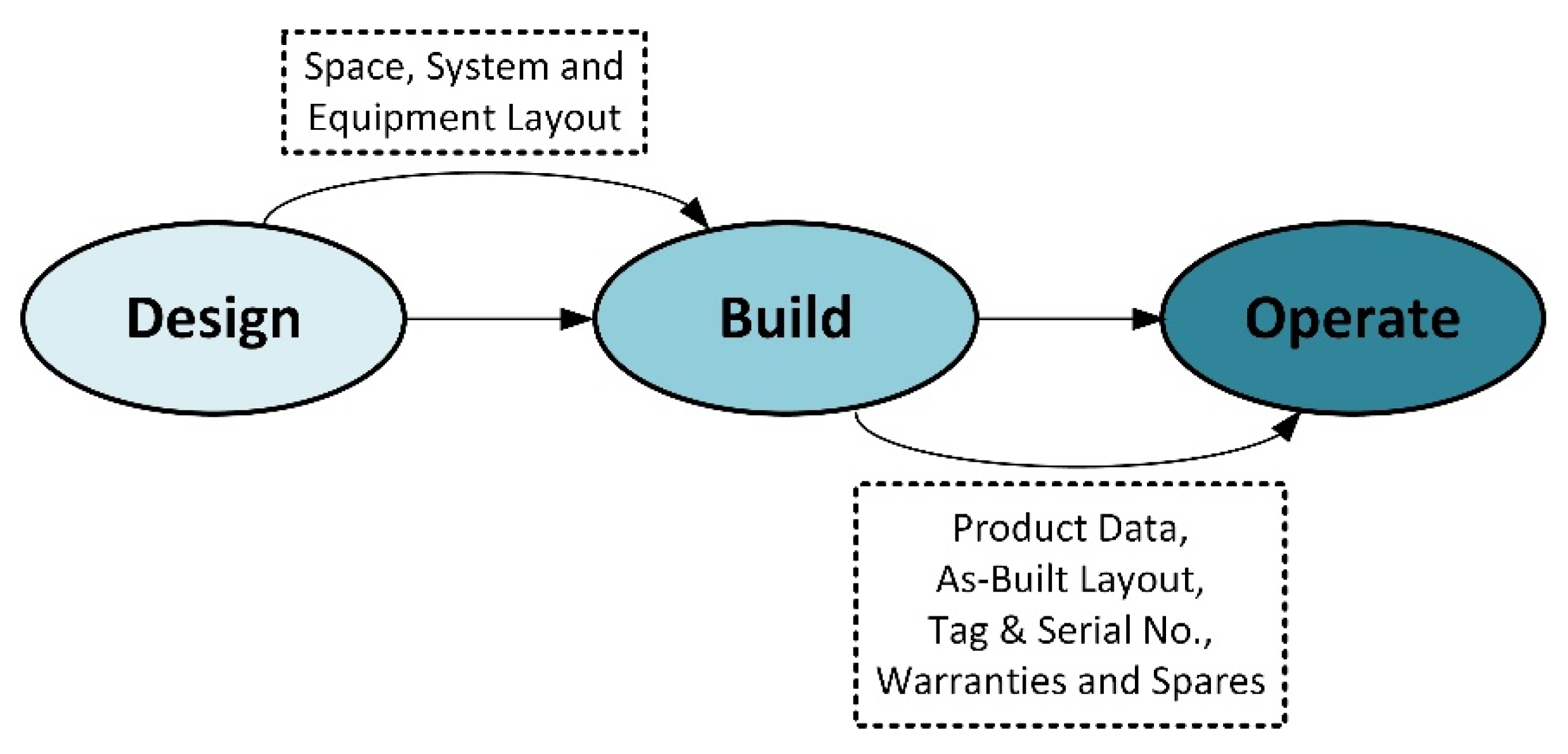
Figure 1. COBie process (Adapted from East William, 2007).
Applsci 12 01304 g001
Figure 2. COBie data structure (Adapted from East William, 2007).
Applsci 12 01304 g002
Figure 3. Example of COBie floor sheet (Adapted from SampleCOBieSpreadsheet provided by Autodesk).
Applsci 12 01304 g003
Figure 4. IFC-COBie, data exchange process (Adapted from East Willam, 2007).
Applsci 12 01304 g004
Figure 5. The references for developing the port COBie Schema.
Applsci 12 01304 g005
Figure 6. Determining COBie components—categorization.
Applsci 12 01304 g006
Figure 7. Configuration of port BIM-based COBie worksheet.
Applsci 12 01304 g007
Figure 8. Configuration of port BIM-based COBie schema.
Applsci 12 01304 g008
Figure 9. Research methodology for implementing the port COBie System.
Applsci 12 01304 g009
Figure 10. Dynamo-based port COBie data processing system.
Applsci 12 01304 g010
Figure 11. The process of Dynamo modeling for port COBie system.
Applsci 12 01304 g011
Figure 12. COBie data classification (e.g., caisson).
Applsci 12 01304 g012
Figure 13. Reconfigured port COBie spreadsheet in order for creating shared parameters.
Applsci 12 01304 g013
Figure 14. For creating shared parameters based on the port COBie for implementing port COBie input system.
Applsci 12 01304 g014
Figure 15. Converting COBie data into shared parameters.
Applsci 12 01304 g015
Figure 16. COBie system with project parameters.
Applsci 12 01304 g016
Figure 17. Port BIM model after COBie data input.
Applsci 12 01304 g017
Figure 18. The entire implementation process for the port COBie system.
Applsci 12 01304 g018
Figure 19. The last step of port COBie System, the output of port COBie spreadsheet.
Applsci 12 01304 g019
Table 1. Information requested by COBie in each phase.
Construction PhaseStakeholdersRequired Information
Architectural ProgrammingDesignerContact, Facility, Floor, Space, Zone
Architectural DesignDesignerType, Component, Attribute
Coordinated DesignDesignerType, Component, Manufacturer Information (in Component), System, Coordinate, Connection
Construction Document DesignerSpatial Assets, Manufacturer Information (in Component), Fixed Assets, Document, Attribute
Construction MobilizationContractorDocument
Construction 60% CompleteContractorSubcontractor Contract Information, Manufacturer Contract Information, Room Tag, Government Furnished Product, Bar Codes, Approved Submittals, Attribute
Beneficial OccupancyContractorSpatial Assets, Equipment Assets, Parts and Warranty Contract, Replacement Parts, Detailed Parts Set
Fiscal CompletionContractorUpdated previous phase information, as needed
Table 2. Existing COBie systems.
System NameUse PurposeCOBie Data ProcessingUsage Phase
dRoufusTo generate COBie dataCOBie data from spreadsheet were extracted from BIM tool, then are imported to the system.Planning
Onuma SystemTo generate COBie dataIFC is extracted from BIM tool, then it is imported to the system, COBie data are generated using the system.
COBie data formed spreadsheet were extracted from BIM tool, then are imported to the system.
Planning
AECOsim Building DesignerTo generate COBie dataIFC is extracted from BIM tool, then it is imported to the system, COBie data are generated using the system.Design
Revit,To generate COBie dataCOBie data are entered using Plug-in, then a spreadsheet is extracted.Design
EcoDomusConstruction
cBIM, To generate COBie dataFirst, COBie data are entered into COBie spreadsheet, then sheet is imported to the system.Construction
AiM 6.3Operation
Publisher’s Note: MDPI stays neutral with regard to jurisdictional claims in published maps and institutional affiliations.