Article

Structural Design and Position Tracking of the Reconfigurable SCARA Robot by the Pre-Filter AFE PID Controller

Changzhou Campus, Jiangsu Provincial Key Laboratory of Special Robot Technology, Hohai University, Changzhou 213022, China
*
Author to whom correspondence should be addressed.
These authors contributed equally to this work.
Appl. Sci. 2022, 12(3), 1626; https://doi.org/10.3390/app12031626
Submission received: 17 October 2021 / Revised: 30 January 2022 / Accepted: 31 January 2022 / Published: 3 February 2022

Abstract

:
The selective compliance assembly robot arm (SCARA) has been developed for decades and has been widely used in industry due to its light structure, quick response and high stiffness in a specific axis. In this work, we designed a reconfigurable SCARA robot with extensible physical space by adjusting the number of modular arms. Considering potential structural failure due to vibration, we employed a multi-objective optimization method based on the finite element method to optimize the bolt connectors between the modules. Compared with the classic finite element optimization method, this method focuses on the key factors affecting the precision of the reconfigurable robot; we used the fitting method of the multi-objective function to obtain the influential factors, which make the optimization results more consistent with a real situation. Then, exploiting the acceleration feedback enhanced (AFE) control strategy, a pre-filter AFE PID controller is proposed by introducing a pre-filter to effectively suppress the system disturbance, which is caused by gaps between the joints when the robot operates at high speed. Experiments show that the reconfigurable SCARA robot still has strong stability under the continuous disturbance of a 2 kg hanging plate weight.

1. Introduction

The SCARA robot with a light structure, quick response and high stiffness has attracted extensive attention from industry and academia. The SCARA robot is a planar joint-type industrial robot. It has four joints, including three mutually parallel revolving joints for positioning and orientation on a plane, and a moving joint perpendicular to the plane to complete the vertical movement of the load. Although various types of SCARA robots have been used in manufacturing and modern factories to carry out repetitive, overloaded, and dangerous tasks instead of humans, the current SCARA robots cannot achieve adaptability to physical space due to their fixed structure and size, and they are difficult to adapt to diversified production manufacturing. Therefore, the SCARA robot can be flexibly interchanged in a variety of physical spaces through a reconfigurable design, which will have extensive applications in industry.
Reconfigurable robots are usually composed of replaceable modules, which can complete various tasks by changing their structure. The connection between modules will exert an important effect on the performance of the reconfigurable robot [1,2]. Several connection methods have been reported in recent years, such as magnetic attraction, pin connection and bolted connection. The ATRON reconfigurable robot [3] and the M-TRAN reconfigurable robot [4] have adopted the SMA coil to realize a magnetic connection between modules. The PolyBot reconfigurable robot [5] and the Crystalline reconfigurable robot [6] have employed a pin connection to integrate into modules for quick installation. Although the magnetic connection is simple and convenient, it has a serious lack of stability and is only suitable for use in special applications. The pin connection is firmer and more stable compared with the magnetic connection, but it is only used in the reconfigurable robots with low precision requirements due to fitting interference, such as the Morpho reconfigurable robot [7]. In addition, the bolt connection is more stable and precise compared with the magnetic connection, but there is still a slight gap between the modules. When the robot operates at high speed, the elasticity of the bolt connector will further enhance the vibration of the robot, which will cause the centerline deviation of the bolt contactor, and cause the bolt contactor to wear and loosen. The electrical and mechanical interactions within the structure generate complex patterns of vibration which may prevent the system from reaching the correct working conditions. Meanwhile, these gaps will greatly amplify the disturbance, which makes the control of the reconfigurable robot have high nonlinearity and strong hysteresis. Therefore, an advanced control system that can effectively suppress the disturbance is also crucial to improve the accuracy of reconfigurable robots. Maide Bucolo et al. proposed a control strategy to ensure optimal working conditions based on the excitation of the hidden dynamics induced by imperfections [8]. Moreover, many advanced control methods have been developed to improve the control accuracy of robot, such as robust control [9], adaptive control [10,11], sliding mode control [12], and boundary control [13]. Zhong et al. [14] proposed a variable structure controller based on fractional calculus to eliminate the disturbance. He et al. [15,16] proposed an adaptive impedance controller and an adaptive neural network controller to deal with the uncertainty of the impedance model. Although these advanced control methods have been proposed for a long time, they can only be realized in the laboratory due to the complex structure and harsh operating conditions. It is difficult to really apply them to industrial robots, so the industrial robots have mainly used the classic proportional-integral-derivative (PID) controller in the past few years.
In recent years, the acceleration feedback enhanced controller (AFE controller) has drawn great attention due to its simple structure and low requirements for operating conditions. Morbi et al. [17] proposed an acceleration-limited proportional derivative controller to enhance the stability of admittance control. Xu et al. [18,19] showed that the joint acceleration feedback with an accelerometer damps out the oscillations substantially in explicit force control. In addition, an AFE controller can effectively suppress the system disturbance, and have good compatibility with the traditional industrial controller [20]. Kikuuwe [21] proposed a new position controller that is suitable for use as the internal position servo of an admittance controller with bounded actuator forces. The novel position controller approximately behaves as a proportional-integral-derivative (PID) controller with an acceleration feedforward in normal situations and as a sliding mode controller when the actuator force is saturated [22,23]. The admittance controller employing the new position controller realizes smooth transitions between saturated periods and unsaturated periods. Moreover, it quickly responds to changes in the applied force even when the actuator force is saturated, leading to better stability and smoothness. The classic AFE controller can suppress the disturbance by setting the gain K, but high-gain is difficult to obtain in most cases due to the constraints of the control structure in the actual system.
In this work, we proposed a reconfigurable SCARA robot with extensible physical space by adjusting the number of modular arms. First of all, the upper arm of the SCARA robot was designed in three different modules, including the forepart module, the middle part module and the rear-end module, which are connected through bolt connectors. Secondly, the multi-objective optimization method based on finite element method was employed to optimize the bolt connectors between the modules. Then, an improved pre-filter AFE PID controller was devised to suppress the disturbance inside the robot. Finally, the experimental setup of the reconfigurable SCARA robot was established to evaluate the structural design and pre-filter AFE PID controller.

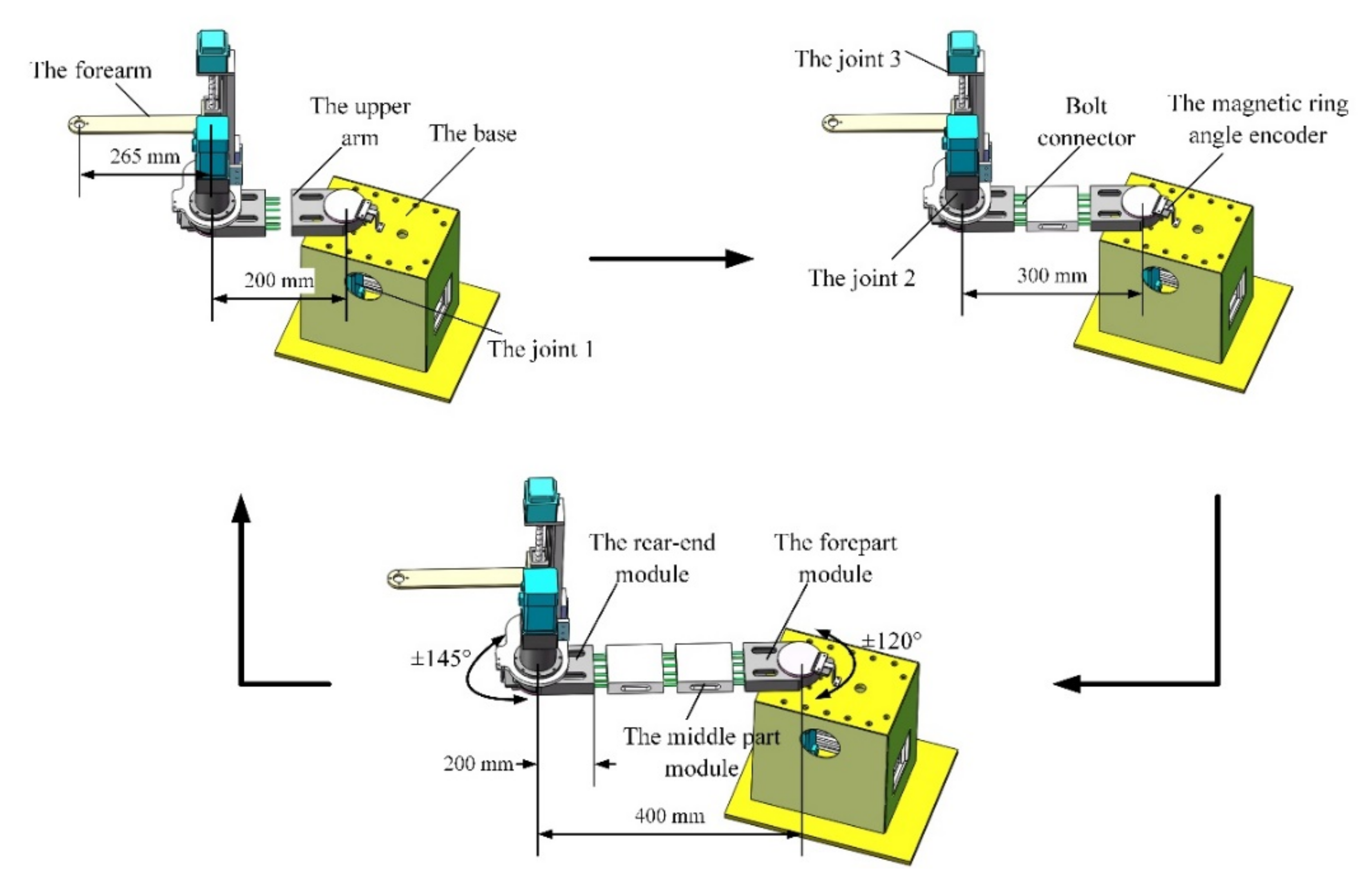
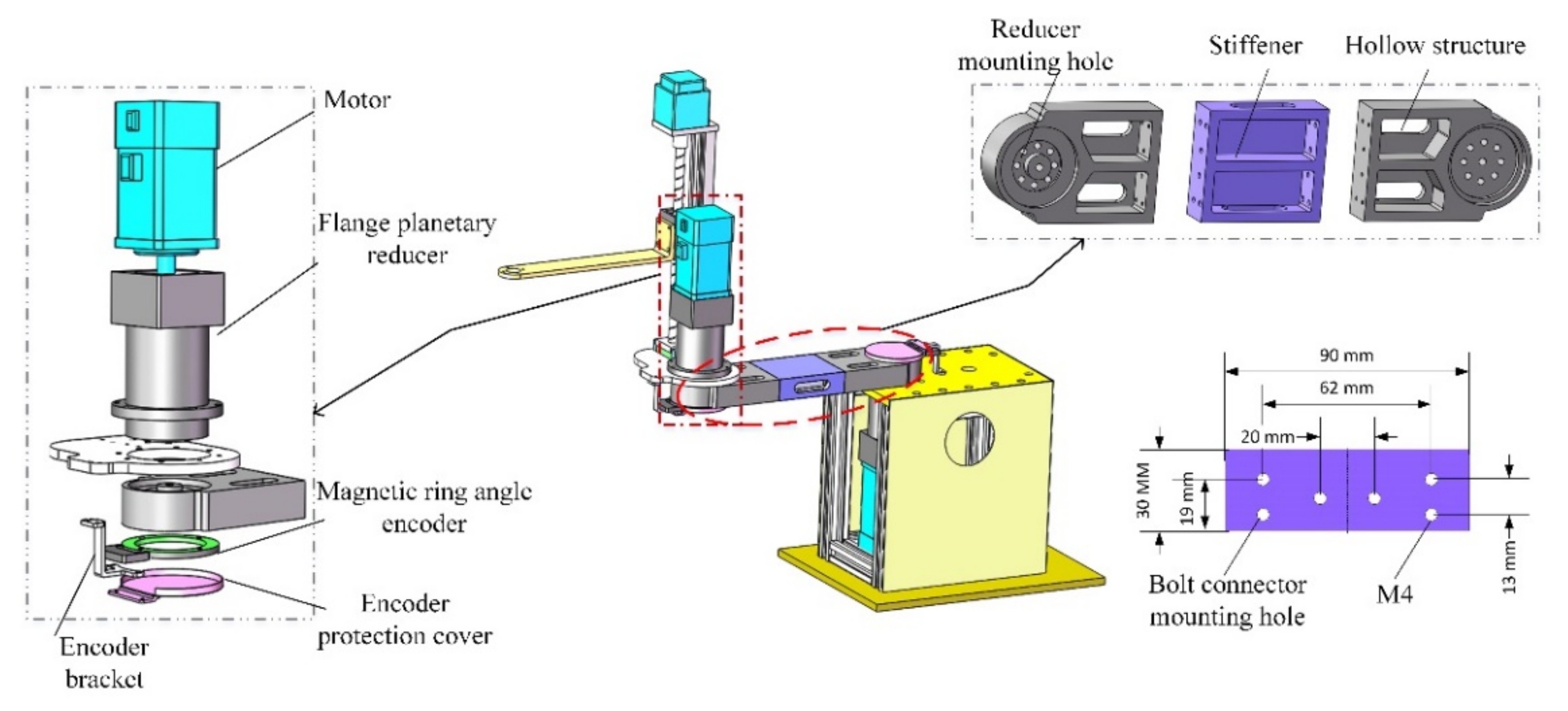
2. Mechanical Design

As shown in Figure 1, the main components of the SCARA robot (RRP) include the base, upper arm, forearm, joint 1, joint 2, joint 3, joint 4, and ball screw splines. Joint 1 and joint 2 are the rotating joints, which are used to drive the upper arm and the forearm, respectively, to realize the location of the SCARA robot on the plane. Joint 3 is a translation joint, which is used to connect with the ball screw through the synchronous belt for the vertical movement of the end effector. Joint 4 is a rotating joint to connect with the splines through the synchronous belt for the orientation of the load. The forearm of SCARA robot is used to connect the ball screw splines and joint 2. Additionally, the upper arm is used to connect joint 1 and joint 2.
The ball screw splines at the end of the SCARA robot are connected with the motor at the second joint through the synchronous belt, and it is necessary to adjust the synchronous belt when adjusting the physical space through the forearm of SCARA robot, which is a task of high complexity. However, the upper arm of SCARA robot is only used to connect joint 1 and joint 2, and there is no transmission mechanism between them. When changing the length of the upper arm, there is no need to adjust the other mechanisms. Therefore, we changed the length of the upper arm by adjusting the number of modular arms. Figure 1 and Figure 2 show the structure of the reconfigurable SCARA robot. The upper arm is composed of three modules, including the forepart module, the middle part module and the rear-end module. To reduce installation error and improve the strength and stiffness of the robot, the joint flanges are designed in the forepart module and the rear-end module to connect the reducers. The middle part module is composed of two identical modules. Users can choose the number of middle part modules to achieve a variety of physical spaces. As shown in Figure 1, the length of the upper arm can be increased by adding the middle part modules to obtain a larger working range, for example, from 200 mm to 300 mm or 400 mm. The modules are connected through bolt connectors. Each module adopts a hollow design, which is convenient for the worker to put in and tighten the bolt connectors. In addition, the internal parts of each module are designed with stiffener to increase the strength of the module. The main geometric parameters of the robot are shown in Table 1.
To reduce the manufacturing costs and simplify the joint structures of the robot, we used the flange planetary reducer instead of the classic harmonic reducer, and efficient transmission is achieved through simple bolt connection. In addition, the magnetic ring angle encoder is installed on the outer end of the joint, which obtains in real-time the actual angle of the joint, and achieves a closed-loop control. In this work, the experimental prototype is mainly used to confirm the feasibility of the reconfigurable design for the upper arm, which is closely related to joint 1, joint 2 and the upper arm, so joint 4 and the splines are omitted.

3. Structure Optimization

3.1. Multi-Objective Optimization Models

The SCARA robot operates at high speed in the horizontal direction, and has a high acceleration at the start and stop stages, which makes the upper arm subject to large shear force and torque. In addition, the elasticity of the bolt connector will further enhance the vibration of robot, which will cause the tiny centerline deviation of the bolt contactor, and cause the bolt contactor to wear and loosen. Therefore, the real-time clamping force of the bolt connectors should be enhanced.
As shown in Figure 3, the mechanical model of the bolt connector is simplified into two groups of axial force composed of elastic force and damping force. In addition, it is considered that the elastic force and damping force act in the same direction. When the SCARA robot operates, one group of axial forces is compressed and the other group is stretched due to the effect of shear force and torque. Meanwhile, a tiny gap is produced, which causes the bolt connector to wear. The real-time clamping force can be expressed as Equation (1).
F = F 0 1 + f w K A n
where F0 is the pretension of bolt connector, F is the real-time clamping force of the bolt connector, and A is the equivalent contact area. It can be seen that when n, fw and K are constant, increasing F0 and A can effectively improve the real-time clamping force. However, when F0 increases, the pressure exerted by the bolt connector will increase. If the thickness of the clamped part is not enough, it may be damaged due to excessive pressure. In addition, when the thickness of the clamped part and equivalent contact area are increased, a larger contact area will be required and the weight of module will increase rapidly. Therefore, F0, A and c (the thickness of the clamped part) affect each other, in a complex nonlinear relationship.
To reduce the complexity of the optimization model, key factors, including F0 (the pretension of bolt connector), c (the thickness of the clamped part) and the width t, are taken as the optimization variable based on Equation (1). L (maximum deformation), M (weight) and f (first-order natural frequency) are taken as the optimization objectives. The two modules are connected by six M4 bolts. The strength grade of the bolt is 4.8, and the maximum pretension is F0 = 2634 N. The material of the module is aviation aluminum alloy 7075. The range of sample groups and the initial values are determined according to the mechanical design manual and the volume of robot, which are listed in Table 2.
The Box–Behnken experimental method is used to arrange the sample groups at high level, and avoid the wrong nonlinear fitting results between the variables and the optimization objective. According to this method, the finite element models with different sample groups are established, the partial data of which are listed in Table 3.
Considering that the multi-objective optimization model presents as highly nonlinear, a phenomenological model based on finite element analysis data is employed to approximate the complex optimization model. The phenomenological model depicting the bolt connector should be compact and accurate. Thus, the least square method and regression equation are used in this work, and fitted models with high precision are obtained by Design-Expert software, which are listed in Table 4. (Where x1 equals c, x2 equals t, and x3 equals F0). The negative correlation coefficient R2 and variation coefficient C.V are used to estimate the fitting accuracy of the model. It can be seen that the correlation coefficient R2 is close to 1, and the variation coefficient C.V is close to 0, and the fitting accuracy is very high.

3.2. Optimization Results

According to the NSGA-II algorithm, the Pareto solution set and plane projection are obtained, as shown in Figure 4. The blue dot * represents the Pareto solution. The red dotted line indicates the first-order natural frequency before optimization, and the brown dotted line indicates the weight before optimization. The black arrow indicates the optimization direction of each optimization objective. Because the deformation before optimization is large, all points in the Pareto solution set meet the optimization objective. According to the analysis, it can be seen that there are six optimal solutions meeting each optimization objective. The values are listed in Table 5. Because small first-order natural frequency will cause low-order vibration, so the solution with higher first-order natural frequency is preferred as the optimization value. Therefore, No. 6 is the optimization value in Table 5. The optimized size is rounded to facilitate the processing of parts, and the pretension of bolt connector F0, the thickness of the clamped part c and the width t are 1700 N, 9 mm and 30 mm, respectively. The comparisons between the optimized design and the initial design are listed in Table 6. It can be seen that the maximum deformation L is reduced by 67.23%, and the first-order natural frequency is increased by 8.4%. The improvement is relatively obvious. The weight M increases slightly, but it can be ignored due to the very small impact on the robot.

4. Pre-Filter Acceleration Feedback Enhanced PID Controller

4.1. Pre-Filter Acceleration Feedback Enhanced Control Strategy

The modules of the reconfigurable SCARA robot are connected by bolt contactors, which will inevitably generate a slight gap at the joint. When the robot operates at high speed, the gap will greatly amplify the disturbance, which makes the control of the robot have high nonlinearity and strong hysteresis. Meanwhile, this system is a multi-input single-output complex system, the input of which includes stimulus signals, disturbance signal and so on. Therefore, a new pre-filter AFE control strategy was proposed to achieve high robustness.
According to the Euler–Lagrange equation, the dynamic equation of a single joint of the reconfigurable SCARA robot can be expressed as Equation (2).
J q ¨ = τ + C q , q ˙ . q ˙ G q F q , q ˙
where J is the inertia coefficient, q is the position vector, τ is the input torque, Δ is the disturbance torque, C q , q ˙ . q   ˙ is the Coriolis force, G (q) is the static torque, and F q , q ˙ is the friction torque.
Then the pre-filter is integrated into the classic AFE control strategy, and pre-filter AFE control strategy is shown in Figure 5.
High-gain acceleration feedback can be expressed as Equation (3). According to Equations (2)–(4) can be obtained.
τ = k v ˙ q ¨
τ = k 1 + k J v ˙ + k J + k M q k J + k M q = C q , q ˙ . q ˙ + G q + F q , q ˙
where k is the gain constant and v ˙   is the output of the upper controller. The system structure Equation (5) can be obtained by introducing the pre-filter B(s)/A(s),
τ = k J + k v ˙ + k J + k B s A s M q k J + k B s A s
where B(s)/A(s) is the transfer function of the pre-filter. B(s) and A(s) are the Laplace transform of output and input respectively. According to Equations (5) and (2), the dynamic equation of a single rotational joint can be re-expressed as Equation (6),
J q ¨ = 1 1 k + 1 J v ˙ + B s 1 k + 1 A s 1 k + 1 A s M q B s 1 k + 1 A s J k + 1 A s
It can be seen that the gain constant k exists in the reciprocal. When the gain constant k is larger, the anti-disturbance ability of the control system is stronger. Let k → + ∞, Equation (7) can be approximately obtained,
J q ¨ = J v ˙ + B s A s A s M q B s A s A s
According to the system Equation (6), it can be seen that the disturbance torque needs to pass through a filter before disturbing the control system. Therefore, the pre-filters A(s)/B(s) play an important role in suppressing the system disturbance, while the gain constant k is transformed into an intermediate parameter, which does not appear in other aspects of the controller. Moreover, according to the swing experiment, the disturbance frequency range of the load (hanging plate weight) of the reconfigurable SCARA robot is 0~0.3 Hz, which is the low frequency range. Therefore, the high-pass filter L(s) was used to suppress low-frequency disturbances. The pre-filters can be expressed as Equation (8),
B s A s = c s + c , L s = B s A s A s = s s + c
where c is the positive constant. According to Equations (7) and (8), the control system can be expressed as Equation (9),
J q ¨ = J v ˙ + s s + c M q s s + c

4.2. Controller

The proportional-integral-derivative (PID) algorithm is widely used in various industrial robots because of its simplicity, efficiency and reliability. However, because of the constant parameters of the classical PID algorithm, it is difficult to effectively maintain the high tracking ability of the reconfigurable SCARA robot. Therefore, the pre-filter AFE control strategy is integrated into the series PID controller to effectively suppress the disturbance and improve the tracking performance. The structure of the controller is shown in Figure 6.
The tracking error of position is defined as e x = x d x . Where   x d is the desired position, then the position PID of the controller can be expressed as Equation (10),
v d = K P x e x + K D x e ˙ x + K I x e x d t
where v d is the desired speed of the system, KPx, KDx, KIx represents the proportional parameter, derivative parameter and integral parameter of position PID, respectively. Through the trial-and-error method, KPx = 1.2, KDx = 1.5, KIx = 0.4. Furthermore, the sample frequency of the position PID is 1000 Hz. The digital form of the position PID can be expressed as Equation (11) based on incremental PID.
Δ u x k = u x k u x k 1 = K P x + K I x + K D x e x k K P x + 2 K D x e x k 1 + K D x e x k 2 e x k = x d k x k
where xd(k) is the desired position of the system, xk is the actual position of the k-th sample, and ux(k) is the output of the position PID.
The tracking error of speed is defined as   e v = v d v . Where v is the desired speed, then the speed PID of the controller can be expressed as Equation (12),
v ˙ d = K P v e v + K D v e ˙ v + K I v e v d t
where v ˙ d is the desired acceleration, KPv, KDv, KIv represents the proportional parameter, derivative parameter and integral parameter of speed PID respectively. Through the trial-and-error method, KPv = 0.16, KDv = 12, KIv = 0. Furthermore, the sample frequency of the speed PID is 4000 Hz. The digital form of the speed PID can be expressed as Equation (13) based on incremental PID.
Δ u v k = u v k u v k 1 =   K P v + K I v + K D v e v k K P v + 2 K D v e v k 1 + K D v e v k 2 e v k = v d k v k
where vd(k) is the desired speed of the system, vk is the actual speed of the k-th sample, and uv(k) is the output of the speed PID.
The dynamic equation of a single joint can be expressed as Equation (14),
J R x ¨ = J R v ˙ d + G q + J R v ˙ f + f
where x ¨ represents the actual acceleration of the system, v ˙ f is the output of pre-filter AFE, f is the disturbance of the system and R is the distance from the weight center of robot to the rotation center of the joint. According to the pre-filter AFE control strategy, v ˙ f and f should be expressed as Equation (15),
J R v ˙ f + f f = L s = s s + c
According to Equations (14) and (15), the output v ˙ f of the system is expressed as Equation (16).
v f = C R J J R v ˙ d + G q J R x ¨ d t . d t
The proposed parameters are taken into consideration for the closed loop system in MATLAB Simulink, as shown in Figure 7a. The Bode diagram shows that the closed loop system with such proposed parameters is stable (Figure 7b).

5. Experiments and Discussions

The control system and prototype of the reconfigurable SCARA robot is shown in Figure 8. The upper arm is made of 7075 high-strength aluminum alloy, and the other parts are made of 6061 aluminum alloy to ensure light weight and high strength. The control system of the reconfigurable SCARA robot mainly includes a controller and servo driver. The servo driver is also called a “gain amplifier”, the function of which is similar to that of a frequency converter acting on an ordinary AC motor. Moreover, the STM32 controller with type of STMF103VET6 made by Xingyi Electronic Technology Co., Ltd. was adopted to control the robot, and obtain the operating information of the robot. The servo driver debugged by TCQ Electrical Technology Co., Ltd. was matched with the motor. The upper computer is used to receive the operating information of the robot and realize the status monitoring of the robot. The main components of the robot are listed in Table 7.
To evaluate the multi-objective optimization method and pre-filter AFE PID controller, and, considering the disturbance signal has the greatest influence on the first joint, the trajectory tracking experiments of the first joint were carried out under continuous disturbance. According to the swing experiment, the disturbance frequency of the reconfigurable SCARA robot was 0~0.3 Hz. Considering the experimental error and other abrupt signals, c was set to 3 in this experiment. According to Equations (11) and (13), the digital form of the position PID and the speed PID can be expressed as Equation (17).
Δ u x k = 3.1 e x k 4.2 e x k 1 + 1.5 e x k 2 Δ u v k = 12.16 e v k 24.16 e v k 1 + 12 e v k 2
During the experiment, the first joint of the robot was rotated circularly in the range of 0~25 deg based on the expected trajectory. The initial 0 deg position was set when the upper arm and the forearm were parallel to each other, and the clockwise direction was the positive direction. In addition, a 2 kg hanging plate weight was suspended at the end of the robot. When the robot operates, the hanging plate weight swings irregularly due to the inertial force, which produces continuous disturbance to the robot. The experimental platform is shown in Figure 8b.
Figure 9a shows the tracking responses of the pre-filter AFE PID controller and classical PID controller when the number of middle part modules was 0. The desired trajectory is a half sinusoidal wave with amplitude of 25 deg and frequency of 0.2 Hz. Portion B shows the robot changing the direction. At this stage, the first joint undergoes three phases: deceleration, stop and acceleration, which will cause a large error due to inertial force and reducer backlash. Figure 9c,d are the enlarged views of portion A and portion B separately. Because of the continuous disturbance of hanging plate weight, the classical PID controller had a large error, and the maximum error was 0.216, while the tracking error curves of pre-filter AFE PID controller were relatively stable in Figure 9c. The maximum tracking error of the classical PID controller was 0.582, while that of pre-filter AFE PID controller was 0.426 in Figure 9d. Figure 9b shows the trajectory tracking error. The pre-filter AFE PID controller only had a large error when the first joint changed direction, and the error in other phases was relatively small. However, the classical PID controller was seriously affected by continuous disturbance. Besides the large error at the stage of the robot changing the direction, there were also large errors in the other stages, such as portion A. These results further show that the pre-filter AFE PID controller has a smaller tracking error and higher robustness than the classical PID controller.
A half sinusoidal wave excitation with amplitude of 25 deg and frequency of 0.4 Hz was employed to drive the robot when the number of middle part modules was 1. The tracking response and error are plotted in Figure 10. Portion C in Figure 10a represents the initial operation phase of the robot. At this phase, the joint suddenly accelerated from the static state, which caused a large tracking error due to the inertial force and reducer backlash. Portion D is the error fluctuation caused by the continuous disturbance of the hanging plate weight. Figure 10c,d are the enlarged views of portion C and portion D, respectively, and it can be seen that the pre-filter AFE PID controller had a faster stability speed and a smaller tracking error than the classical PID controller. Figure 10b shows the trajectory tracking error, the maximum error of pre-filter AFE PID controller was 0.547, while that of classical PID controller was 0.625. In addition, the classical PID controller was seriously affected by the continuous disturbance of the hanging plate weight, and obvious error fluctuations occurred many times in the whole operation process, while the pre-filter AFE PID controller was more robust. The results were the same as the previous experiment, and showed that the Pre-Filter AFE PID controller had a better ability to suppress the disturbance than the classical PID controller.

6. Conclusions

In this work, we designed a reconfigurable SCARA robot with extensible physical space. Through the extensible component composed of cable and the middle part module, the reconfigurable SCARA robot can be easily interchanged into three models, which makes it possible to configure robots in real time and save customers a great deal of cost and time. It shows broad application prospects in fields where robots are frequently replaced, such as, product packaging and product loading and unloading. We firstly integrated the reconfigurable design into the SCARA robot, and users can choose the number of modules to obtain a variety of physical spaces. Then, in consideration of structural failure due to vibration, a multi-objective optimization method based on the finite element method was used to optimize the bolt connectors between the modules. It can be seen that the maximum deformation L was reduced by 67.23%, and the first-order natural frequency was increased by 8.4%. The improvement is relatively obvious. Subsequently, a new pre-filter AFE control strategy was integrated into the series PID controller to effectively suppress the disturbance and improve the tracking performance. The experiment results show that the reconfigurable SCARA robot still has strong stability under the continuous disturbance of a 2 kg hanging plate weight. In addition, compared with the classical PID controller, the pre-filter AFE PID controller has a better ability to suppress the disturbance. However, the backlash of the reducer from the experimental prototype is too large, which will cause large tracking errors. In future, high precision reducers and novel optimization methods will be taken into production to guarantee its accuracy and stability.

Author Contributions

Conceptualization, Y.W. and D.Z.; methodology, C.Z.; software, D.M.; validation, Y.W. and D.Z.; formal analysis, C.Z. and G.T.; data curation, L.Z.; writing—original draft preparation, C.Z.; writing—review and editing, C.Z. and Y.W. All authors have read and agreed to the published version of the manuscript.

Funding

This work was financially supported by the National Key Research and Development Program of China (2020YFB1312900), the financial support from the National Natural Science Foundation of China (51975184 and 52105573), and the Fundamental Research Funds for the Central Universities (B210202124). The authors gratefully acknowledge the supports.

Institutional Review Board Statement

Not applicable.

Informed Consent Statement

Not applicable.

Conflicts of Interest

The authors declare no conflict of interest.

References

  1. Song, C.Y.; Feng, H.; Chen, Y. Reconfigurable mechanism generated from the network of Bennett linkages. Mech. Mach. Theory 2015, 88, 49–62. [Google Scholar] [CrossRef]
  2. Valero, F.; Díaz-Rodríguez, M.; Vallés, M.; Besa, A.; Bernabéu, E.; Valera, Á. Reconfiguration of a parallel kinematic manipulator with 2T2R motions for avoiding singularities through minimizing actuator forces. Mechatronics 2020, 69, 102382. [Google Scholar] [CrossRef]
  3. EOstergaard, H.; Kassow, K.; Beck, R.; Lund, H.H. Design of the ATRON lattice-based self-reconfigurable robot, Auton. Robots 2006, 21, 165–183. [Google Scholar]
  4. Murata, S.; Yoshida, E.; Kamimura, A.; Kurokawa, H.; Tomita, K.; Kokaji, S. M-TRAN: Self-reconfigurable modular robotic system, IEEE/ASME Trans. Mechatron 2002, 7, 431–441. [Google Scholar]
  5. Yim, M.; Zhang, Y.; Roufas, K.; Duff, D.; Eldershaw, C. Connecting and disconnecting for chain self-reconfiguration with PolyBot, IEEE/ASME Trans. Mechatron 2002, 7, 442–451. [Google Scholar]
  6. Rus, D.; Vona, M. Crystalline robots: Self-reconfiguration with compressible unit modules, Auton. Robots 2001, 10, 107–124. [Google Scholar]
  7. Yu, C.H.; Haller, K.; Ingber, D.; Nagpal, R. Morpho: A self-deformable modular robot inspired by cellular structure. In Proceedings of the IEEE/RSJ International Conference on Intelligent Robots and Systems, Nice, France, 22–26 September 2008; pp. 3571–3578. [Google Scholar]
  8. Bucolo, M.; Buscarino, A.; Famoso, C.; Frasca, M. Control of imperfect dynamical systems. Nonlinear Dyn. 2019, 98, 2989–2999. [Google Scholar] [CrossRef]
  9. Wai, R.-J.; Chen, P.-C. Robust neural-fuzzy-network control for robot manipulator including actuator dynamics. IEEE Trans. Ind. Electron. 2006, 53, 1328–1349. [Google Scholar] [CrossRef]
  10. Zamanian, A.H.; Richer, E. Adaptive notch filter for pathological tremor suppression using permanent magnet linear motor. Mechatronics 2019, 63, 102273. [Google Scholar] [CrossRef]
  11. Yang, C.; Jiang, Y.; He, W.; Na, J.; Li, Z.; Xu, B. Adaptive parameter estimation and control design for robot manipulators with finite-time convergence. IEEE Trans. Ind. Electron. 2018, 65, 8112–8123. [Google Scholar] [CrossRef]
  12. Kim, J.; Jin, M.; Choi, W.; Lee, J. Discrete time delay control for hydraulic excavator motion control with terminal sliding mode control. Mechatronics 2019, 60, 15–25. [Google Scholar] [CrossRef]
  13. He, W.; Zhang, S. Control design for nonlinear flexible wings of a robotic aircraft. IEEE Trans. Control Syst. Technol. 2017, 25, 351–357. [Google Scholar] [CrossRef]
  14. Zhong, G.; Deng, H.; Li, J. Chattering-free variable structure controller design via fractional calculus approach and its application. Nonlinear Dyn. 2015, 81, 679–694. [Google Scholar] [CrossRef]
  15. He, W.; Chen, Y.; Yin, Z. Adaptive neural network control of an uncertain robot with full-state constraints. IEEE Trans. Cybern. 2016, 46, 620–629. [Google Scholar] [CrossRef] [PubMed]
  16. He, W.; Dong, Y.; Sun, C. Adaptive neural impedance control of a robotic manipulator with input saturation. IEEE Trans. Syst. Man Cybern. Syst. 2016, 46, 334–344. [Google Scholar] [CrossRef]
  17. Morbi, A.; Ahmadi, M.; Chan, A.; Langlois, R. Stability-guaranteed assist-as-needed controller for powered orthoses. IEEE Trans. Control Syst. Technol. 2014, 22, 745–752. [Google Scholar] [CrossRef]
  18. Xu, W.L.; Han, J.D.; Tso, S.K. Experimental study of contact transition control incorporating joint acceleration feedback. IEEE/ASME Trans. Mechatron. 2000, 5, 292–301. [Google Scholar] [CrossRef] [Green Version]
  19. Xu, W.L.; Han, J.D.; Tso, S.K.; Wang, Y.C. Contact transition control via joint acceleration feedback. IEEE Trans. Ind. Electron. 2000, 47, 150–158. [Google Scholar] [CrossRef]
  20. Aguirre-Ollinger, G.; Colgate, J.; Peshkin, M.; Goswami, A. Inertia compensation control of a one-degree-of-freedom exoskeleton for lower-limb assistance: Initial experiments. IEEE Trans. Neural Syst. Rehabil. Eng. 2012, 20, 68–77. [Google Scholar] [CrossRef] [Green Version]
  21. Kikuuwe, R. A sliding-mode-like position controller for admittance control with bounded actuator force. IEEE/ASME Trans. Mechatron. 2014, 19, 1489–1500. [Google Scholar]
  22. Wang, C.; Liu, X.; Yang, X.; Hu, F.; Jiang, A.; Yang, C. Trajectory tracking of an omni-directional wheeled mobile robot using a model predictive control strategy. Appl. Sci. 2018, 8, 231. [Google Scholar] [CrossRef] [Green Version]
  23. Chao, C.-T.; Sutarna, N.; Chiou, J.-S.; Wang, C.-J. Equivalence between fuzzy PID controllers and conventional PID controllers. Appl. Sci. 2017, 7, 513. [Google Scholar] [CrossRef] [Green Version]
Figure 1. The modular design of SCARA robot.
Applsci 12 01626 g001
Figure 2. The structure diagram of reconfigurable SCARA.
Applsci 12 01626 g002
Figure 3. Simplified vibration diagram of bolt connector.
Applsci 12 01626 g003
Figure 4. Pareto solution set and plane projection. (a) Pareto solution; (b) plane projection of maximum deformation and weight; (c) plane projection of maximum deformation and first-order natural frequency; (d) plane projection of weight and first-order natural frequency.
Applsci 12 01626 g004
Figure 5. Pre-filter acceleration feedback enhanced control strategy.
Applsci 12 01626 g005
Figure 6. Pre-filter acceleration feedback enhanced PID controller.
Applsci 12 01626 g006
Figure 7. (a) Simulink control system; (b) the bode diagram.
Applsci 12 01626 g007
Figure 8. Control system of the reconfigurable SCARA robot. (a) Schematic drawing; (b) prototype of the experimental setup.
Applsci 12 01626 g008aApplsci 12 01626 g008b
Figure 9. The trajectory tracking experiments under a half sinusoidal wave excitation of 0.2 Hz with amplitude 25°. (a) Tracking performance; (b) the trajectory tracking error; (c) enlarged view for portion A in (a); (d) enlarged view for portion B in (a).
Applsci 12 01626 g009aApplsci 12 01626 g009bApplsci 12 01626 g009c
Figure 10. The trajectory tracking experiments under a half sinusoidal wave excitation of 0.4 Hz with amplitude 25°. (a) Tracking performance; (b) the trajectory tracking error; (c) enlarged view for portion C in (a); (d) enlarged view for portion D in (a).
Applsci 12 01626 g010aApplsci 12 01626 g010b
Table 1. The parameters of Denavit and Hartenberg.
Link i𝜃𝑖
Rot z [deg]
𝑑𝑖 Disp z [mm] 𝑎𝑖
Disp x [mm]
𝛼𝑖
Rot x [deg]
1−120° ≤ 𝜃1 ≤ 120°0200/300/4000
2−145° ≤ 𝜃2 ≤ 145°02650
300 ≤ d3 ≤ 2000180°
Table 2. The range of sample groups.
F0/Nc/mmt/mm
Minimum value1500627
Maximum value25001033
Table 3. Partial data of finite element models.
No.c/mmt/mmF0/NL/mM/kgf/Hz
183325005.67 × 10−51.105501.6
282725005.97 × 10−50.801430.69
382715004.36 × 10−50.801430.48
483020005.16 × 10−50.953465.64
563015001.53 × 10−40.821418.34
663320001.01 × 10−40.983451.35
7103025004.36 × 10−51.054500.58
8102720003.87 × 10−50.902463.15
9103015002.85 × 10−51.054500.48
1083020005.16 × 10−50.953465.64
11103320003.53 × 10−51.209538.92
1283315003.96 × 10−51.105501.66
1362720001.76 × 10−40.669383.19
1463025002.04 × 10−40.821418.57
1583020005.16 × 10−50.953465.64
1683020005.16 × 10−50.953465.64
Table 4. The fitted models.
ModelsGoodness of Fit
R2C.V
L = 5.16 7.86 x 1 + 0.446 x 2 + 0.994 x 3 + 6.44 x 1 2 + 0.187 x 2 2 0.359 x 3 2 1.24 x 1 x 2 0.408 x 1 x 3 + 0.027 x 2 x 3 × 10 5 0.99460.0902
f = 465.64 41.46 x 1 + 35.75 x 2 + 0.06 x 3 6.55 x 1 2 + 0.064 x 2 2 + 0.4 x 3 2 + 1.9 x 1 x 2 0.033 x 1 x 3 0.067 x 2 x 3 0.99990.0011
M = 2.09 0.076 x 1 0.099 x 2 5.3 × 10 4 x 3 0.01 x 1 2 + 0.0014 x 2 2 + 1.33 × 10 7 x 3 2 + 4.63 × 10 3 x 1 x 2 0.97190.0164
Table 5. The optimal solution set.
No.c/mmt/mmF0/NL/mM/kgf/Hz
19.3227.3615473.32 × 10−50.871457.92
28.272915584.25 × 10−50.9459.62
38.9628.6815783.49 × 10−50.919468.27
48.8529.0415483.78 × 10−50.932470.59
58.8329.3915774.05 × 10−50.95474.98
68.8429.7317233.17 × 10−50.977478.93
Table 6. Comparison between the optimized design scheme and the initial design scheme.
Optimization ObjectiveInitial Design SchemeOptimized Design SchemeRate of Change
L/m1.01 × 10−43.31 × 10−567.23% reduction
M/kg0.9830.9931.02% increase
f/Hz451.35489.268.4% increase
Table 7. Components of the reconfigurable SCARA robot.
NameTypeManufacturerMain Parameters
First joint motor60ST-M00630Yichuan Motor Co., Ltd.Rated Power: 400 W
Maximum torque: 3.9 N.m
Rated speed: 3500 rpm
Second joint motor60ST-M01330Yichuan Motor Co., Ltd.Rated Power: 200 W
Maximum torque:1.9 N.m
Rated speed: 3500 rpm
Third joint motor57EBP98ALCTCQ Electrical Technology Co., Ltd.Rated Power: 200 W
Maximum torque: 1.27 N.m
Step angle: 1.8 deg
First joint reducerPLH90-40SKISIA Co., Ltd.Reduction ratio: 40
Maximum allowable torque: 84 N.m
Dorsal space: 30 arcmin
Second joint reducerPLH60-35SKISIA Co., Ltd.Reduction ratio: 35
Maximum allowable torque: 224 N.m
Dorsal space: 30 arcmin
Angle encoderMRA7D049AA025B00Renishaw CorporationResolution: 5 µm
Grid spacing: 20 µm
STM32 controllerSTMF103VET6Xingyi Electronic Technology Co., Ltd.Operating rate: 72 MHz,
3 ADCs and 1 DAC
ComputerINS14-3476DELL CorporationProcessor: Intel i5-7200U
RAM: 4 GB
Publisher’s Note: MDPI stays neutral with regard to jurisdictional claims in published maps and institutional affiliations.

