Article

A Pelvic Reconstruction Procedure for Custom-Made Prosthesis Design of Bone Tumor Surgical Treatments

by
Gilda Durastanti
1,
Claudio Belvedere
1,
Miriana Ruggeri
1,*,
Davide Maria Donati
2,
Benedetta Spazzoli
2 and
Alberto Leardini
1
1
Movement Analysis Laboratory, IRCCS Istituto Ortopedico Rizzoli, 40136 Bologna, Italy
2
III Clinical Department, IRCCS Istituto Ortopedico Rizzoli, 40136 Bologna, Italy
*
Author to whom correspondence should be addressed.
Appl. Sci. 2022, 12(3), 1654; https://doi.org/10.3390/app12031654
Submission received: 11 January 2022 / Revised: 1 February 2022 / Accepted: 2 February 2022 / Published: 4 February 2022
(This article belongs to the Special Issue Advanced Imaging in Orthopedic Biomechanics)

Abstract

:
In orthopaedic oncology, limb salvage procedures are becoming more frequent thanks to recent major improvements in medical imaging, biomechanical modelling and additive manufacturing. For the pelvis, surgical reconstruction with metal implants after tumor resection remains challenging, because of the complex anatomical structures involved. The aim of the present work is to define a consistent overall procedure to guide surgeons and bioengineers for proper implant design. All relevant steps from medical imaging to an accurate 3D anatomical-based model are here reported. In detail, the anatomical 3D models include bone shapes from CT on the entire pelvic bone, i.e., including both affected and unaffected sides, and position and extension of the tumor and soft tissues from MRI on the affected side. These models are then registered in space, and an initial shape of the personalized implant for the affected side can be properly designed and dimensioned based on the information from the unaffected side. This reported procedure can be fundamental also for virtual pre-surgical planning, and the design of patient-specific cutting guides, which would result is a safe margin for tumor cut. The entire procedure is here shown by describing the results in a single real case.

1. Introduction

In orthopaedic oncology, limb salvage procedures for the pelvis requires tumor resection by an appropriate excision followed by careful corresponding reconstruction of the affected bone and soft tissues [1]. Pelvic resections and reconstructions are classified by tumor extension and the section of bone to be resected, i.e., iliac or periacetabular or pubic location [2]. In particular, according to the Enneking and Dunham classification [2], type I involves the iliac region, type II the periacetabular region, type III the pubis or ischium, and type IV the lateral part of the sacrum. Most of these reconstructions involve the acetabulum, which implies the replacement of the hip joint [3,4]. For all pelvic resection and reconstruction procedures, the primary goals are the restoration of the physiologic joint motion and the maintenance of good quality of life [4]. To date, surgical reconstruction after tumor resection in the pelvis remains a challenge, because of the critical and complex anatomical structures involved. A major critical aspect is the bone cut, which must be performed to achieve an adequate margin around the tumor, but also to preserve as much skeletal structure and joint function as possible, including adequate bone stock and soft tissues such as ligaments and tendons [1,5,6,7].
Important advancements in pelvic reconstruction using biological reconstruction such as structural pelvic allografts or autografts, arthrodesis and endoprostheses have been shown [8], though a high rate of complications, including infection, dislocation and mechanical failure, have been reported [5,9,10,11,12]. More recently, there has been a strong interest in custom-made prostheses, particularly after the great developments of additive manufacturing, also known as 3D-printing. A custom-made prosthesis is a fully personalized implant, which is aimed at achieving a more anatomical reconstruction, i.e., more respectful of the original anatomy, and a better match with patient’s residual bone, and thus a smaller risk of loosening, infection, fractures, and any possible mechanical failure. It also allows a precise pre-operative planning of the surgical procedure, this including the positioning of the prosthesis, and the setting of corresponding bone cuts. The potential better long-term clinical and functional results are supported by the good short-term results [3,5,7,13,14,15,16,17,18,19,20,21,22,23,24]. 3D printed implants have attracted much attention nowadays also because of faster production and lower costs, together with the accurate optimization and control of the overall geometry, both in terms of the external roughness and internal topology [25].
Surgical reconstructions at the pelvis using custom-made implants are showing encouraging results, both at the acetabulum, ileum, and sacrum sections, with low complication rates, although wound healing problems have been reported [17,26]. On the other hand, any custom-made implant requires careful medical imaging and time-consuming modelling and design [6]. Nevertheless, this digital process allows a precise identification of the tumor and, thus, a careful computer-based pre-surgical planning of the bone resection [5,24,27], though this virtual surgery depends on the quality of medical imaging and the software tools utilized and the experience and ability of the surgical team. As mentioned, computer-based design and 3D printing of these implants have the potential to result in advanced porous metal implants, with different geometries of the internal and external structures, and with no limits to their complexity. It is also possible to use a number of different materials, with mechanical properties similar to those of the natural anatomical structures [25,28,29]. This further technical advancement has been assessed already also in custom-made implants for complex pelvic reconstructions [13,17,30,31]. The final surgical result of these reconstructions, also in term of an accurate prosthesis-to-bone contact, largely relies also on how bone resections are performed, and thus on the design and manufacturing of the so-called patient-specific cutting guides [1,15,30,32,33,34,35].
The anatomical design of these implants based on digital bone models should imply the knowledge of the shape of both the affected and unaffected hemipelvis; the former must provide an accurate location and extension of the tumor, the latter should be considered a best possible target for the final reconstruction [15,27,36,37]. The exact definition of the tumor, together with the skeletal and soft tissue structures, requires complete computer-based anatomical models, to be obtained via multimodal medical image scans using computed tomography (CT) and magnetic resonance imaging (MRI), and accurate 3D reconstructions. These final 3D models, observed separately and also registered superimposed on one another in 3D space, allow visualization, identification and localization of all important anatomical structures, necessary for a careful pre-surgical planning and implant design [3,38,39]. For these procedures, and for the following virtual surgery planning, a close collaboration between surgeons, radiologists, bioengineers, and technicians is necessary. Despite these techniques must have been exploited massively for modern custom-made implants, only a few papers have reported in detail the procedures implied in this modelling part of the personalisation [15,27,30].
The aim of the present work is to report on an original procedure in orthopaedic oncology for the 3D design of custom-made implants for the pelvis. In particular, the procedure is here shown for a single clinical case and follows the full process from medical imaging to final 3D computer-based models of the tumor resection and bone reconstruction. All these steps are based on personalised models of the pelvis of the patient, including the bones and the tumor, as derived from of CT and MRI images using state-of-the-art semi-automatic segmentation tools. The steps of this procedure are also defined under careful indication of the surgical team, including of course the critical decision on the osteotomies for tumor resection. This technical procedure includes for the first-time spatial registrations and also mirroring of the unaffected hemipelvis to the affected one, as a reliable subject-specific homologous reference for a possible most accurate definition of these cutting planes. In every step, the main accuracy parameters are tracked.

2. Methods

The technical steps here reported refer to a female patient, a 54 year-old woman (height: 168 cm; weight: 70 Kg; body mass index: 24.8 kg/m2) affected by a malignant bone tumor in the left pelvic bone, in particular a condrosarcome grade II. According to the Enneking and Dunham classification [2], this patient had a type I + II + III partial lesion, due to the extension of the tumor on the iliac region, in the acetabulum and, partially, also in the pubic and ischiatic area. The patient had not received chemotherapy at the time of medical imaging data collection.

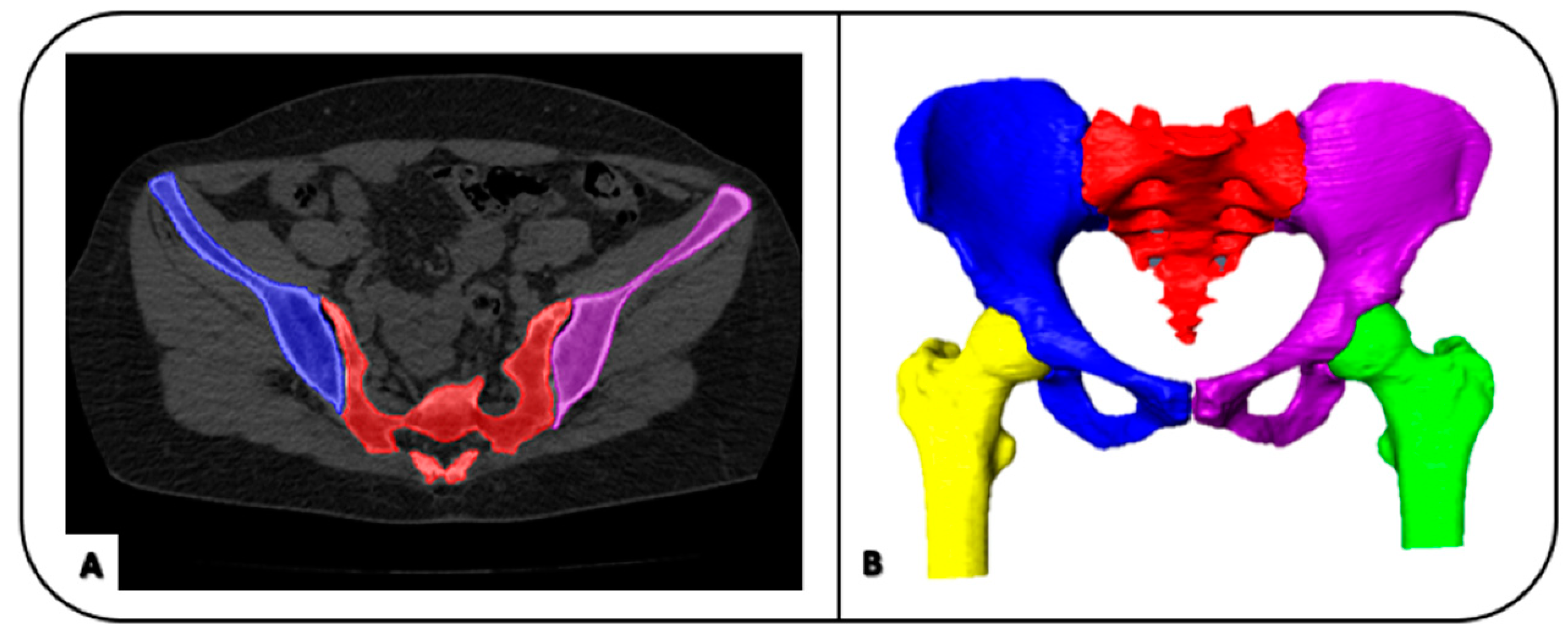
2.1. Image Processing: Image Segmentation and Geometrical Modelling

The patient underwent pre-operative computed tomography (CT) of the pelvis, sacrum and proximal femur, and magnetic resonance imaging (MRI) of the pelvis regions involved in the tumor lesion. The acquired images were exported in Digital Imaging and Communications in Medicine (DICOM) files and imported into an image visualization and processing software, Amira (Zuse Institute Berlin ZIB, Dahlem, Berlin, Germany—Thermo Fisher Scientific, Waltham, MA, USA). A semi-automatic segmentation was performed (Figure 1A) [40], for anatomical structure reconstructions. For every slice of the scan, the external surface of the bones and the tumor were identified and depicted, to obtain their 3D models (Figure 1B) by merging these 2D segmented silhouettes.
Several tools of the Amira software package were used to obtain accurate patient-specific models of the above reported anatomical structures. In more details, among these tools, thresholding was preferred, according to the Hounsfield Unit (HU) values for the bones and the tumor, which was set slice by slice, also depending on the quality of the corresponding CT or MRI medical image. The 3D model of the bones was generated from segmentation of the former (Figure 2A), the 3D model of the bones and tumor was generated from segmentation of the latter (Figure 2B). The full segmentation and modelling process was performed by a single expert operator. These two 3D models were exported in binary stereolithography format (STL), and then imported into a reverse engineering software, Geomagic Control (2014.3.0.1781, 3D Systems, Rock Hill, SC, USA).

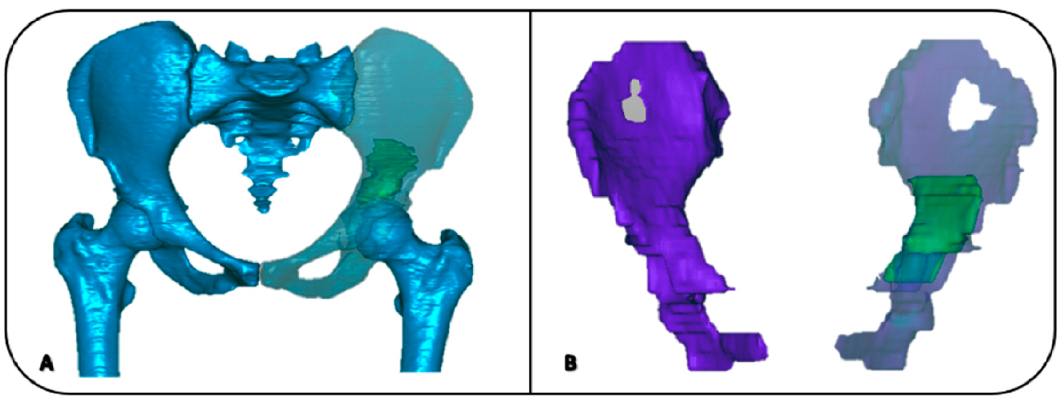
2.2. Registrations of 3D Models

To obtain a complete model of the pelvis suitable for the planning of the bone cuts and the design of the implant device, which must include shapes of both bones and tumor, registrations between CT-based and MRI-based models were performed in Geomagic as well as the following steps. These registrations in general were executed via best-fit spatial alignments based on 3D models of rigid objects achieved by the established iterative closest point (ICP) algorithm [41]. This best-fit registration of two objects, i.e., the so-called “reference” and the “test”, consists of an optimal spatial matching to minimize an overall distance error between their surfaces. This results in a transformation matrix, together with the estimation of the mean and root mean square (RMS) errors of the transformation.
Two major such registration procedures were performed, both bone-to-bone. A first registration was between the CT-based and the MRI-based models, as the goal is to take the 3D shape of the tumor on the bone model of the affected hemipelvis (Figure 3). Because the bone is poorly represented in MRI-based models, the final result is to superimpose exactly the tumor, which better identified in MRI, with the best representation of the bone, which is best obtained from CT. In other words, the portion of bone from MRI is registered to the corresponding from CT; the same transformation is then applied to the tumor to get the final bone plus tumor model.
A second registration then is between the affected and the unaffected hemipelvis. To get a first anatomical shape to the metal implant meant to replace the resected bone stock, the unaffected hemipelvis is mirrored and registered to the affected hemipelvis. A mirroring plane is defined at the pubic symphysis (Figure 4A), and the unaffected is mirrored by spatial registration. This can be performed by considering the whole hemipelvis, as well as any part of it; several such trials can be performed, and the transformation with the lowest registration error can be selected (Figure 4A). Eventually a model with the two hemipelvis superimposed and the tumor in the correct position is obtained (Figure 4B). In this model, the same 3D planes representing bone cuts at the affected hemipelvis are used also to cut the unaffected hemipelvis, and thus to separate a most accurate possible shape of the implant for the replacement.

2.3. Design of Bone Resection Planes

The cutting planes were defined on this 3D anatomical model under strict indications by the surgical team members. They very carefully identify the tumor also by looking at relevant original MRI images, and then plan its excision by setting the relevant bone resection cuts. Locations and orientations of these resection planes in the computer model were decided by identifying the exact position and extension of the tumor and by considering a sufficient safety margin, here taken initially at about 20 mm, which takes into account also the resolution of MRI and CT scans. Additional more surgical and clinical criteria are also considered for a final compromise for this value, such as the smallest possible bone stock to be removed, a best preservation of the critical soft tissues, and a best large contact between the host bone and the implant, for its optimal final integration. In case of resection of the iliac bone (type I + II), it is preferred to define a so-called “roof” cut, with an angle of about 100° ≈ 110° with respect to the anatomical frontal plane of the pelvis, for a best fit of the prosthesis on the host bone, as well as for a secure support to the vertical forces exchanged over the hip.
The defined resection planes are introduced into the model, and, according to these, cuts of the bone models are performed, both on the affected hemipelvis, i.e., left, and on the mirrored and registered unaffected hemipelvis. In the present case, this virtual surgical planning involves the iliac region, the acetabulum and partially the pubic and ischiatic regions, for a total of four cutting planes (Figure 5).

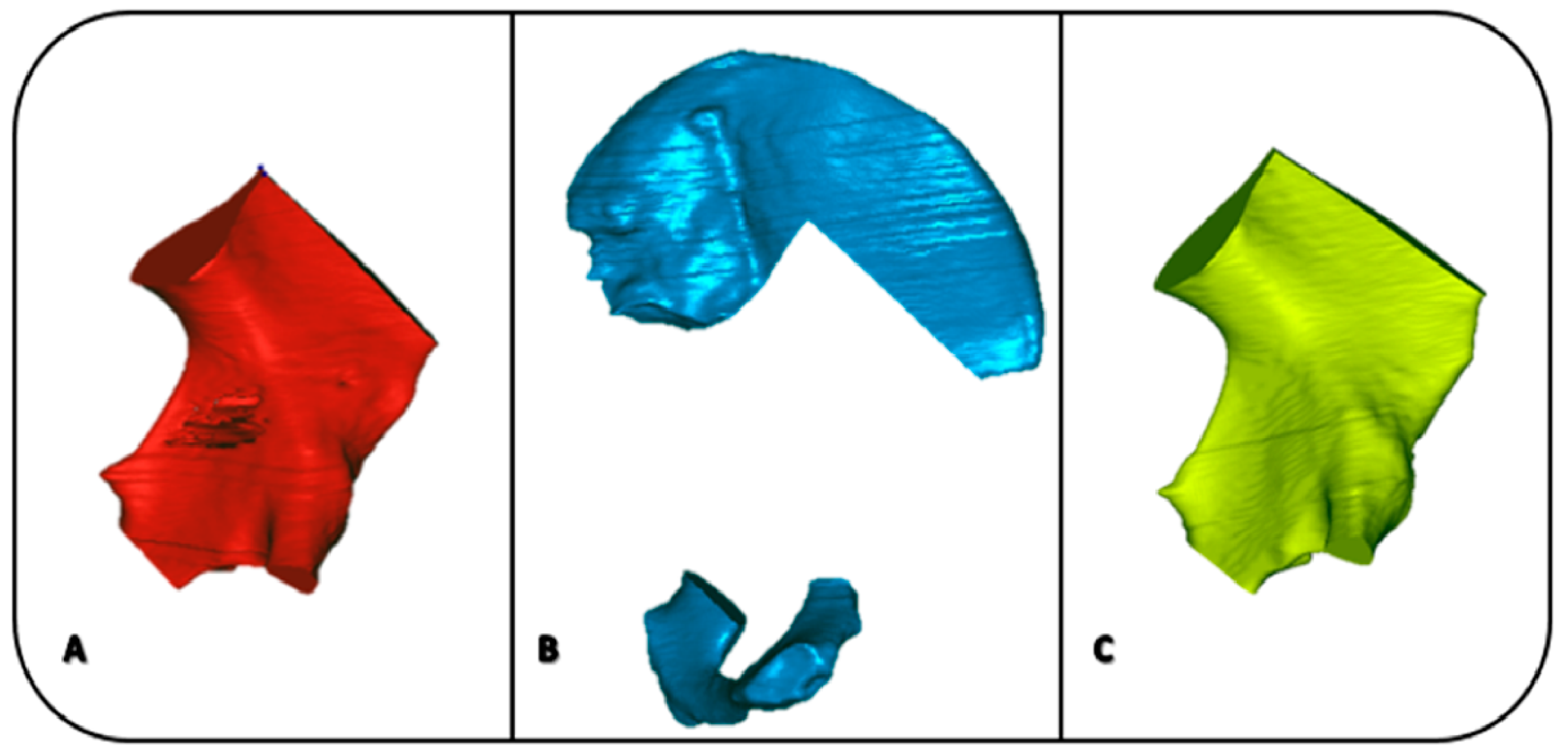
2.4. Creation of the Models for the Final Surgery

Additional bone models are thus defined from virtually performing these bone cuts. The resection of the affected left hemipelvis results in the model of the region of the bone containing the tumor, to be removed during surgery (Figure 6A), and the model of the part of the pelvis meant to host the implant, i.e., the pelvis bone on which the implant will be fixed (Figure 6B).
A third new model is obtained by the virtual bone cuts performed on the mirrored and registered right hemipelvis; the part in correspondence of the tumor is meant to represent a best possible shape of the implant, to be implanted in the host bone as defined in Figure 6C.

2.5. Virtual Planning Analysis and Post-Operative Evaluations

From these models, a great deal of relevant information can be taken, such as tumor volume and areas of the hosting bone sections (Figure 7), in case to amend position and orientation of the planes and to start with a new overall surgical plan. A suitable surgical approach and optimal location and orientation of the fixation elements, such as screws and plates, can also be adjusted. This overall procedure ensures that the design of the initial shape of the implant is based on the exact patient-specific bone and tumor morphology, to obtain a full custom-made limb salvage plan.

3. Results

The best-fit registration gives as results a transformation matrix, besides the mean error and the root mean square (RMS) of the registration.

3.1. Registration of 3D Models

The mean error and RMS value of the first best-fit registration, i.e., from MRI-based to CT-based models, are 0.98 and 1.44 mm, respectively.

3.2. Creation of Final Models for Implant Design

The corresponding results for the second best-fit registration, i.e., between the affected hemipelvis and the unaffected hemipelvis after mirroring and matching procedures, are 0.87 and 1.16 mm, respectively.

3.3. Virtual Planning Analysis and Post-Operative Evaluations

The results of the virtual planning analysis are shown in Table 1. In particular, the area of cutting sections in the second model defined in the current procedure (the affected hemipelvis meant to host the implant) and its volume, the volume of the first model (the hemipelvis section containing the tumor) and the volume of the third model (the model representing a first possible shape of the implant).

4. Discussion

Limb salvage for pelvic tumor is a complex surgical treatment and represents a challenge for orthopaedic oncology surgeons. The primary goal in the removal of the tumor and replacement with an implant is to achieve an adequate margin and to preserve the relationship between the remaining tissues [5,8]. The recent advent of 3D printing technology, together with the use of CT and MRI, provides an important solution for these problems [7,14,15,38,42]. In the present study, an original procedure is defined, with all steps from these medical imaging to an accurate 3D anatomical—based model with the shape of the implant; this would be fundamental also for virtual pre-surgical planning, and the design of patient-specific cutting guides. The entire procedure is here shown by depicting the results in a single real case.
These guides are fundamental, for the surgeons to achieve the result designed in the pre-operative planning, in particular the perfect intra-operative positioning and fixation of the prosthesis, which would result also in a safe margin for full tumor removal [3]. Knowing from the virtual models the exact shape of the bones, and the exact position and orientation of the cuts, together with the experience of the surgical access and overall room, the design of these cutting guides and their additive manufacturing with suitable material is straightforward. In the operating theatre, their correct position is usually checked with the help of drawings from pre-operative planning and also with sterile bone models from the case. Once the cutting guides are placed in the correct position, bone is cut with oscillating saw, and then bone and guides are removed.
The anatomical 3D computer models include bone shapes from CT, and position and extension of the tumor and soft tissues from MRI. These models, in their digital format, are registered in space (Figure 3), i.e., positioned in corresponding locations; from this, a process starts for an initial shape of the personalized implant to be obtained (Figure 4, Figure 5, Figure 6 and Figure 7, Table 1). The major originality of the present procedure is the definition of a best possible initial virtual model for the final personalized implant (Figure 6C). This is designed to restore skeletal anatomy as best as possible, by mirroring the corresponding contralateral part (Figure 4) and thus it matches well with the remaining bone to host the implant (Figure 6B) by definition. These two models do come from different hemipelvis, but the cuts are performed once, when these hemipelvis are mirrored and registered one over the other (Figure 4B and Figure 5). In other words, the same virtual bone cuts (planes a-b-c-d in Figure 5) identify the bone-stock with the tumor (to be removed, in the affected hemipelvis) and the corresponding contralateral part (for the replacement, in the unaffected hemipelvis), respectively parts A and C in Figure 6. This guarantees a perfect match between these models, for a final successful replacement in the operating theatre, apart of course the anatomical asymmetry also caused by the tumor and the spatial registration error, which are expected however to be small. These are the only sources of the present very small difference (about 35 mm2Table 1) of the matching faces in the corresponding resection areas, which is clinically acceptable. In any case, the very final design of the implant can cope and adjust this mismatch easily.
These operations were all performed at the computer, using suitable software tools, but can also be replicated by using physical models, thanks to current accessible 3D printers, able to manufacture corresponding objects by the additive technology, now in a fast and cheap way [14]. These physical models are very important both for surgeons and bioengineers, to handle and check the virtual planning by using an exact replica of the case; final recommendations can be made, and refinements can still be performed to the design of the implant and of the treatment. In particular, the fixation elements of the implant and the bone cutting guides are to be checked carefully. This phase is also suitable for the preparation and training of the team, and in case for the explanation of the anatomical conditions and of the relevant surgery to the patient and relatives. The industry is also involved in this process, to assess the final production of the implant (for instance materials, surfaces, porosity, lattice, etc.).
In this report, the ICP registration between the bone models was performed. These spatial registrations can be performed also via the so-called single value decomposition method [38], but in this case a repeatable procedure to identify corresponding anatomical landmarks must be developed and tested, besides the fact that generally the present ICP registration method resulted in a lower error value [38]. The overall computer models after spatial registration between CT- and MRI- based reconstruction of anatomical structures may also involve the soft tissue. Together with the pelvic bones and the tumor, also the muscle-tendon units and even blood vessels can be included, as their location can possibly have a very critical impact with the implant and the surgical instruments such as guides, drills, and saws.
The overall quality of the planning can be checked preoperatively at the computer but also with the physical models. During surgery, additional checks shall be performed. Postoperatively, additional measurements can be taken to validate quantitatively the overall process of segmentation, modelling, registration between models, designing and implanting. A CT scan of the resected bone affected by the tumor can be performed, and its 3D computer model can be compared to the corresponding model defined in the virtual preoperative planning; after a spatial merging of the two models, a root mean square error would well represent the overall quality of the digital and surgical actions [30]. On the other hand, a larger CT scan of the entire operated pelvis can in theory reveal the quality of the entire plan and surgery, but the presence of large metal implants results in severe image artefacts, these being difficult to be removed.
This study has limitations. First of all, the use of a single patient to better explain the procedure; other cases may correspond to more or less complex situations. This was also run by only one trained operator: the result of the present procedure was certainly influenced by this single implementation, in particular the overall process of segmentation and the identification of the tumor. This is by necessity a generalised procedure, because of the uniqueness of each single clinical case in this area; in other words, established standard procedures cannot be defined, as bone tumor location and extension cannot be known and catalogued precisely [2]. In this respect, the role and involvement of the surgeons are fundamental for tumor identification, location, and treatment, together for the definition of the cutting planes and the overall preoperative surgical planning. These resection planes could be better positioned by taking advantage of more cautious considerations and knowledge of the magnitude and direction of the hip joint contact forces; these can be taken generically from the literature, or even by patient-specific measurements, by using state-of-the-art gait analysis and musculo-skeletal models of the lower limbs.

5. Conclusions

A thorough procedure supporting the custom-made design and manufacturing of implants for the surgical treatment of bone tumors at the pelvis is proposed. A few steps are based on established practice in biomechanical modelling, others on original concepts. All these however have been shared with surgeons and industry, as well as discussed within international teams of experts. The present use of both CT and MRI imaging does allow a careful reproduction of the main anatomical structures, including the tumor, resulting in a more accurate planning and implant designing. The procedure could be easily rearranged also for other anatomical complexes, especially where symmetry restoration represents an important scope.

Author Contributions

Conceptualization: G.D., C.B. and A.L.; methodology: G.D. and C.B.; software: G.D. and M.R.; validation: G.D., C.B. and B.S.; formal analysis: G.D.; investigation: G.D. and B.S; resources: D.M.D. and A.L.; writing–original draft preparation: G.D., C.B. and A.L.; writing–review and editing: G.D., C.B., M.R., D.M.D., B.S. and A.L.; visualization: G.D. and M.R.; supervision: C.B. and A.L.; project administration: D.M.D. and A.L.; funding acquisition: A.L. All authors have read and agreed to the published version of the manuscript.

Funding

This study was funded by the Italian Ministry of Economy and Finance, program “5 per mille”.

Institutional Review Board Statement

The study was conducted according to the guidelines of the Declaration of Helsinki, and approved by the Institutional Review Board CE AVEC (number: EM468/2021_47/2014/Oss/IOR_EM1; final amendment approval Prot. Gen 0008191, 27 May 2021).

Informed Consent Statement

Informed consent was obtained from the subject involved in the study.

Data Availability Statement

The datasets generated during the current study are not publicly available but are available from the corresponding author on reasonable request.

Conflicts of Interest

All authors declare that there are no personal or commercial relationships.

References

  1. Park, J.W.; Kang, H.G.; Lim, K.M.; Park, D.W.; Kim, J.H.; Kim, H.S. Bone tumor resection guide using three-dimensional printing for limb salvage surgery. J. Surg. Oncol. 2018, 118, 898–905. [Google Scholar] [CrossRef]
  2. Enneking, W.F.; Dunham, W.K. Resection and reconstruction for primary neoplasms involving the innominate bone. J. Bone Jt. Surg. Am. 1978, 60, 731–746. [Google Scholar] [CrossRef]
  3. Zhu, D.; Fu, J.; Wang, L.; Guo, Z.; Wang, Z.; Fan, H. Reconstruction with customized, 3D-printed prosthesis after resection of periacetabular Ewing’s sarcoma in children using “triradiate cartilage-based” surgical strategy:a technical note. J. Orthop. Translat. 2021, 28, 108–117. [Google Scholar] [CrossRef]
  4. Angelini, A.; Calabro, T.; Pala, E.; Trovarelli, G.; Maraldi, M.; Ruggieri, P. Resection and reconstruction of pelvic bone tumors. Orthopedics 2015, 38, 87–93. [Google Scholar] [CrossRef] [PubMed] [Green Version]
  5. Hennessy, D.W.; Santiago, M.E.A.; Lozano-Calderón, A. Complex Pelvic Reconstruction using Patient-Specific Instrumentation and a 3D-Printed Custom Implant following Tumor Resection. J. Hip Surg. 2017, 2, 061–067. [Google Scholar] [CrossRef]
  6. Matar, H.E.; Selvaratnam, V.; Shah, N.; Wynn Jones, H. Custom triflange revision acetabular components for significant bone defects and pelvic discontinuity: Early UK experience. J. Orthop. 2020, 21, 25–30. [Google Scholar] [CrossRef] [PubMed]
  7. Dong, E.; Wang, L.; Iqbal, T.; Li, D.; Liu, Y.; He, J.; Zhao, B.; Li, Y. Finite Element Analysis of the Pelvis after Customized Prosthesis Reconstruction. J. Bionic Eng. 2018, 15, 443–451. [Google Scholar] [CrossRef]
  8. Fujiwara, T.; Medellin Rincon, M.R.; Sambri, A.; Tsuda, Y.; Clark, R.; Stevenson, J.; Parry, M.C.; Grimer, R.J.; Jeys, L. Limb-salvage reconstruction following resection of pelvic bone sarcomas involving the acetabulum. Bone Jt. J. 2021, 103-B, 795–803. [Google Scholar] [CrossRef]
  9. Ozaki, T.; Hillmann, A.; Bettin, D.; Wuisman, P.; Winkelmann, W. High complication rates with pelvic allografts. Experience of 22 sarcoma resections. Acta Orthop. Scand. 1996, 67, 333–338. [Google Scholar] [CrossRef] [Green Version]
  10. Abudu, A.; Grimer, R.J.; Cannon, S.R.; Carter, S.R.; Sneath, R.S. Reconstruction of the hemipelvis after the excision of malignant tumours. Complications and functional outcome of prostheses. J. Bone Jt. Surg. Br. 1997, 79, 773–779. [Google Scholar] [CrossRef]
  11. Gebert, C.; Wessling, M.; Hoffmann, C.; Roedl, R.; Winkelmann, W.; Gosheger, G.; Hardes, J. Hip transposition as a limb salvage procedure following the resection of periacetabular tumors. J. Surg. Oncol. 2011, 103, 269–275. [Google Scholar] [CrossRef] [PubMed]
  12. Jansen, J.A.; van de Sande, M.A.; Dijkstra, P.D. Poor long-term clinical results of saddle prosthesis after resection of periacetabular tumors. Clin. Orthop. Relat. Res. 2013, 471, 324–331. [Google Scholar] [CrossRef] [PubMed] [Green Version]
  13. Angelini, A.; Trovarelli, G.; Berizzi, A.; Pala, E.; Breda, A.; Ruggieri, P. Three-dimension-printed custom-made prosthetic reconstructions: From revision surgery to oncologic reconstructions. Int. Orthop. 2019, 43, 123–132. [Google Scholar] [CrossRef] [PubMed] [Green Version]
  14. Belvedere, C.; Siegler, S.; Fortunato, A.; Caravaggi, P.; Liverani, E.; Durante, S.; Ensini, A.; Konow, T.; Leardini, A. New comprehensive procedure for custom-made total ankle replacements: Medical imaging, joint modeling, prosthesis design, and 3D printing. J. Orthop. Res. 2019, 37, 760–768. [Google Scholar] [CrossRef] [PubMed]
  15. Park, J.W.; Kang, H.G.; Kim, J.H.; Kim, H.S. The application of 3D-printing technology in pelvic bone tumor surgery. J. Orthop. Sci. 2021, 26, 276–283. [Google Scholar] [CrossRef]
  16. Sun, W.; Li, J.; Li, Q.; Li, G.; Cai, Z. Clinical effectiveness of hemipelvic reconstruction using computer-aided custom-made prostheses after resection of malignant pelvic tumors. J. Arthroplast. 2011, 26, 1508–1513. [Google Scholar] [CrossRef]
  17. Liang, H.; Ji, T.; Zhang, Y.; Wang, Y.; Guo, W. Reconstruction with 3D-printed pelvic endoprostheses after resection of a pelvic tumour. Bone Jt. J. 2017, 99-B, 267–275. [Google Scholar] [CrossRef]
  18. Iqbal, T.; Shi, L.; Wang, L.; Liu, Y.; Li, D.; Qin, M.; Jin, Z. Development of finite element model for customized prostheses design for patient with pelvic bone tumor. Proc. Inst. Mech. Eng. H 2017, 231, 525–533. [Google Scholar] [CrossRef]
  19. Colen, S.; Dalemans, A.; Schouwenaars, A.; Mulier, M. Outcome of custom-made IMP femoral components of total hip arthroplasty: A follow-up of 15 to 22 years. J. Arthroplast. 2014, 29, 397–400. [Google Scholar] [CrossRef]
  20. Fan, H.; Fu, J.; Li, X.; Pei, Y.; Li, X.; Pei, G.; Guo, Z. Implantation of customized 3-D printed titanium prosthesis in limb salvage surgery: A case series and review of the literature. World J. Surg. Oncol. 2015, 13, 308. [Google Scholar] [CrossRef] [Green Version]
  21. Xiu, P.; Jia, Z.; Lv, J.; Yin, C.; Cheng, Y.; Zhang, K.; Song, C.; Leng, H.; Zheng, Y.; Cai, H.; et al. Tailored Surface Treatment of 3D Printed Porous Ti6Al4V by Microarc Oxidation for Enhanced Osseointegration via Optimized Bone In-Growth Patterns and Interlocked Bone/Implant Interface. ACS Appl. Mater. Interfaces 2016, 8, 17964–17975. [Google Scholar] [CrossRef] [PubMed]
  22. Sing, S.L.; An, J.; Yeong, W.Y.; Wiria, F.E. Laser and electron-beam powder-bed additive manufacturing of metallic implants: A review on processes, materials and designs. J. Orthop. Res. 2016, 34, 369–385. [Google Scholar] [CrossRef] [PubMed]
  23. Shah, F.A.; Snis, A.; Matic, A.; Thomsen, P.; Palmquist, A. 3D printed Ti6Al4V implant surface promotes bone maturation and retains a higher density of less aged osteocytes at the bone-implant interface. Acta Biomater. 2016, 30, 357–367. [Google Scholar] [CrossRef] [PubMed]
  24. Angelini, A.; Kotrych, D.; Trovarelli, G.; Szafranski, A.; Bohatyrewicz, A.; Ruggieri, P. Analysis of principles inspiring design of three-dimensional-printed custom-made prostheses in two referral centres. Int. Orthop. 2020, 44, 829–837. [Google Scholar] [CrossRef]
  25. Attarilar, S.; Ebrahimi, M.; Djavanroodi, F.; Fu, Y.; Wang, L.; Yang, J. 3D Printing Technologies in Metallic Implants: A Thematic Review on the Techniques and Procedures. Int. J. Bioprint 2021, 7, 306. [Google Scholar] [CrossRef]
  26. Wang, B.; Hao, Y.; Pu, F.; Jiang, W.; Shao, Z. Computer-aided designed, three dimensional-printed hemipelvic prosthesis for peri-acetabular malignant bone tumour. Int. Orthop. 2018, 42, 687–694. [Google Scholar] [CrossRef]
  27. Fang, C.; Cai, H.; Kuong, E.; Chui, E.; Siu, Y.C.; Ji, T.; Drstvensek, I. Surgical applications of three-dimensional printing in the pelvis and acetabulum: From models and tools to implants. Unfallchirurg 2019, 122, 278–285. [Google Scholar] [CrossRef] [Green Version]
  28. Sohling, N.; Neijhoft, J.; Nienhaus, V.; Acker, V.; Harbig, J.; Menz, F.; Ochs, J.; Verboket, R.D.; Ritz, U.; Blaeser, A.; et al. 3D-Printing of Hierarchically Designed and Osteoconductive Bone Tissue Engineering Scaffolds. Materials 2020, 13, 1836. [Google Scholar] [CrossRef]
  29. Pei, X.; Ma, L.; Zhang, B.; Sun, J.; Sun, Y.; Fan, Y.; Gou, Z.; Zhou, C.; Zhang, X. Creating hierarchical porosity hydroxyapatite scaffolds with osteoinduction by three-dimensional printing and microwave sintering. Biofabrication 2017, 9, 045008. [Google Scholar] [CrossRef]
  30. Wong, K.C.; Kumta, S.M.; Geel, N.V.; Demol, J. One-step reconstruction with a 3D-printed, biomechanically evaluated custom implant after complex pelvic tumor resection. Comput. Aided Surg. 2015, 20, 14–23. [Google Scholar] [CrossRef]
  31. Chen, X.; Xu, L.; Wang, Y.; Hao, Y.; Wang, L. Image-guided installation of 3D-printed patient-specific implant and its application in pelvic tumor resection and reconstruction surgery. Comput. Methods Programs Biomed. 2016, 125, 66–78. [Google Scholar] [CrossRef] [PubMed]
  32. Gouin, F.; Paul, L.; Odri, G.A.; Cartiaux, O. Computer-Assisted Planning and Patient-Specific Instruments for Bone Tumor Resection within the Pelvis: A Series of 11 Patients. Sarcoma 2014, 2014, 842709. [Google Scholar] [CrossRef]
  33. Cartiaux, O.; Paul, L.; Francq, B.G.; Banse, X.; Docquier, P.L. Improved accuracy with 3D planning and patient-specific instruments during simulated pelvic bone tumor surgery. Ann. Biomed. Eng. 2014, 42, 205–213. [Google Scholar] [CrossRef] [PubMed]
  34. Wong, K.C.; Sze, K.Y.; Wong, I.O.; Wong, C.M.; Kumta, S.M. Patient-specific instrument can achieve same accuracy with less resection time than navigation assistance in periacetabular pelvic tumor surgery: A cadaveric study. Int. J. Comput. Assist. Radiol. Surg. 2016, 11, 307–316. [Google Scholar] [CrossRef] [PubMed] [Green Version]
  35. Wong, K.C.; Kumta, S.M.; Sze, K.Y.; Wong, C.M. Use of a patient-specific CAD/CAM surgical jig in extremity bone tumor resection and custom prosthetic reconstruction. Comput. Aided Surg. 2012, 17, 284–293. [Google Scholar] [CrossRef] [PubMed]
  36. Iqbal, T.; Wang, L.; Li, D.; Dong, E.; Fan, H.; Fu, J.; Hu, C. A general multi-objective topology optimization methodology developed for customized design of pelvic prostheses. Med. Eng. Phys. 2019, 69, 8–16. [Google Scholar] [CrossRef] [PubMed]
  37. Park, D.W.L.A.; Park, J.W.; Lim, K.M.; Kang, H.G. Biomechanical Evaluation of a New Fixation Type in 3D-Printed Periacetabular Implants using a Finite Element Simulation. Appl. Sci. 2019, 9, 820. [Google Scholar] [CrossRef] [Green Version]
  38. Durastanti, G.; Leardini, A.; Siegler, S.; Durante, S.; Bazzocchi, A.; Belvedere, C. Comparison of cartilage and bone morphological models of the ankle joint derived from different medical imaging technologies. Quant. Imaging Med. Surg. 2019, 9, 1368–1382. [Google Scholar] [CrossRef]
  39. De Paolis, M.; Sambri, A.; Zucchini, R.; Frisoni, T.; Spazzoli, B.; Taddei, F.; Donati, D.M. Custom made 3D-printed prosthesis in periacetabular resections through a novel ileoadductor approach. Orthopedics 2021. [Google Scholar] [CrossRef]
  40. Van Eijnatten, M.; van Dijk, R.; Dobbe, J.; Streekstra, G.; Koivisto, J.; Wolff, J. CT image segmentation methods for bone used in medical additive manufacturing. Med. Eng. Phys. 2018, 51, 6–16. [Google Scholar] [CrossRef]
  41. Besl, P.J.; McKay, N.D. A method for registration of 3-D shapes. IEEE Trans. Pattern Anal. Mach. Intell. 1992, 14, 239–256. [Google Scholar] [CrossRef]
  42. Bohme, J.; Shim, V.; Hoch, A.; Mutze, M.; Muller, C.; Josten, C. Clinical implementation of finite element models in pelvic ring surgery for prediction of implant behavior: A case report. Clin. Biomech. 2012, 27, 872–878. [Google Scholar] [CrossRef] [PubMed]
Figure 1. The process of geometrical modeling of the bone shape: image segmentation in the 2D images (A) and the final 3D model (B) via Amira software.
Applsci 12 01654 g001
Figure 2. (A) 3D bone models (blue) obtained by segmentation from CT images, including pelvis, sacrum and femur bones. (B) 3D model of the pelvis (purple) obtained by segmentation from MRI images. In both the 3D models of the tumor on the left hemipelvis is depicted in green.
Applsci 12 01654 g002
Figure 3. The 3D result after a best-fit registration of the MRI-based models to CT-based models; again, the model of the tumor from MRI is depicted in green.
Applsci 12 01654 g003
Figure 4. Bone models to depict the procedure for mirroring (A) and spatial matching of the two hemipelvis (B). In (A), the unaffected hemipelvis (in blue, on the left) is to be mirrored to the affected one (in yellow, on the right). This latter model, the affected one, is then matched (B) to the unaffected one (blue); the tumor in the affected hemipelvis (from the registration as in Figure 3) is depicted in green.
Applsci 12 01654 g004
Figure 5. The four cutting planes (a-b-c-d) defined for the four osteotomies necessary to remove the bone stock with the tumor (in green). These virtual osteotomies are performed on both the affected (in yellow) and unaffected (in blue) hemipelvis, after registration as in Figure 4B.
Applsci 12 01654 g005
Figure 6. The three relevant models defined at the end of the procedure, after the registration as in Figure 4B and the bone cuts as in Figure 5: (A) the model of the hemipelvis section containing the tumor; (B) the model of the affected hemipelvis without A, thus intended as the bone to host the prosthesis; (C) the model representing a first shape of the implant, because derived from registered unaffected hemipelvis after applying the same cuts. Because of the overall procedure, the section areas in (B,C) have exactly the same position and orientation.
Applsci 12 01654 g006
Figure 7. Depiction of the sections (in red) at the affected hemipelvis, supposed to host the implant, the upper part in the ilium (A), and the lower part in the ischium and pubis (B).
Applsci 12 01654 g007
Table 1. Area of the cutting sections and volume of the final models obtained.
FIRST MODEL
-
Affected Hemipelvis Meant to Host the Implant
SECOND MODEL
-
Hemipelvis Section Containing the Tumor
THIRD MODEL
-
Model of the First Shape of the Implant
SECTION AREA (mm2)2454.82454.82489.6
VOLUME (mm3)178,601.5103,961.6135,535.6
Publisher’s Note: MDPI stays neutral with regard to jurisdictional claims in published maps and institutional affiliations.

