Article

Capturing a Space Target Using a Flexible Space Robot

1
Key Laboratory of Hydrodynamics of Ministry of Education, School of Naval Architecture, Ocean & Civil Engineering, Shanghai Jiaotong University, Shanghai 200240, China
2
State Key Laboratory of Ocean Engineering, Shanghai Jiaotong University, Shanghai 200240, China
*
Author to whom correspondence should be addressed.
Appl. Sci. 2022, 12(3), 984; https://doi.org/10.3390/app12030984
Submission received: 22 November 2021 / Revised: 16 December 2021 / Accepted: 27 December 2021 / Published: 19 January 2022

Abstract

:
Capturing space targets by space robots is significant for on-orbit service and is a challenging research topic nowadays. This paper focuses on the dynamics and control of capturing a non-cooperative space target by a space robot with a long flexible manipulator. Firstly, the dynamic equation of the flexible space robot is given. The Hertz contact model is used to describe the contact force between the robot and the target. Secondly, an active compliance controller is designed to reduce the capture impact on the robot. Finally, the capture impact on the whole system is analyzed in detail in four scenarios: the combination of two kinds of movement forms and two kinds of relative positions of the robot and the target before capturing. Simulation results indicate that the capturing operation may cause complicated dynamic behaviors such as the vibration of elastic links and the continuous collision of the target. Moreover, the results show that the control method effectively offsets the capture impact on the space robot system. In general, this work lays a theoretical foundation for further study of the dynamic phenomena of the capture process.

1. Introduction

With the development of science and technology, human explorations of space have been growing quickly. A number of space launches have been carried out in recent years to meet the demands of communication, weather monitoring, and the military. However, human space exploration activities have tremendously affected the space environment, leaving a large amount of space debris such as failure satellites, upper rocket stages, and collision derivatives, which bring a significant threat to human space activities. To ensure the security of spacecrafts, some active debris removal (ADR) schemes were proposed, such as lowering the orbit of near-earth target debris and burning them down in the atmosphere, lifting the debris on the geostationary Earth orbit to a graveyard orbit. In all of these schemes, capturing space debris on-orbit is necessary. Since most space debris are non-cooperative and information about them, for instance, mass, centroid location, geometric shape, and motion state, is unknown, the capturing operation is a difficult task to realize.
To date, some capture methods have already been proposed, such as manipulator, net, and hook. Among them, the research of manipulator-based capturing technology is a significant direction [1,2]. Related works include those of McDonald Dettwiler Space and Advanced Robotics Ltd. (MDSAR) who developed a simulation tool to analyze the dynamic behavior between robot and target during contact [3]. Wee and Walker [4] studied the contact between a free-flying space robot and a non-cooperative target. They developed an algorithm to minimize the contact impulse by planning the robot trajectory tracking and impulse minimization. In Cyril and Jaar’s research [5,6], post-capture dynamics of a flexible spacecraft manipulator were studied deeply. Yoshida et al. [7,8,9,10,11,12] carried out extensive studies on the operation of capturing a free-flying/free-floating object by a rigid space robot, including impact dynamics modeling, impulse minimizing, and impedance control. Shibli and Su [13,14] studied the dynamic modeling and control of the capture of a satellite by a rigid space robot. To reduce the difficulty of the capturing operation, Matunaga et al. [15] proposed a contact/push-based control method for reducing the angular momentum of an uncontrolled target satellite. For the same reason, Uyama and Nakanishi [16,17] utilized a controllable compliant wrist installed on a rigid robot to offset the impact of the target satellite. Thai et al. [18] used a Magneto-Rheological (MR) damper to offset the impact from the target satellite too. Xu et al. [19,20] studied the captures of a non-cooperative object and a larger flexible spacecraft by a rigid space robot, respectively. Liu et al. [21] and Yu et al. [22] conducted a series of studies on the dynamics and control of capturing a floating rigid body by a rigid space robot. Nishida et al. [23,24,25,26] studied the dynamics of capturing space debris by a rigid space robot, and some research results about capturing strategy were achieved. Liu et al. [27], Liu et al. [28,29], and Stolfi et al. [30,31] studied the control problem of the capture of a larger tumbling object by multi rigid robot arms. Zarafshan et al. [32,33] studied the control problem of cooperative object manipulation by a rigid-flexible arm. From the studies above, we can see that the capture of space objects using space robots has gained much attention, and there are many research results. However, there still are some problems remaining for further study. For example, in most existing studies, the capture missions are conducted by a rigid space robot. The flexible space robot has a longer manipulator, so the flexible space robot has a larger working space than the rigid space robot. Thus, a flexible space robot could finish the capture mission in a relatively safe position. However, the flexibility brought by the longer manipulator will cause more complex dynamics behaviors of the system during capturing. Such behaviors could make the capture a failure. To date, the research on the capturing operations realized by flexible space robots is insufficient but essential [1]. Therefore, it is essential and meaningful to research the dynamics and control of capturing a non-cooperative target by a flexible space robot.
In this paper, Jourdain’s velocity variation principle is adopted to build the dynamics of a flexible space robot, and the Hertz contact theory is used to describe the contact force between the end-effecters of the manipulator and the target. Moreover, an active controller is designed to reduce the capture impact on the robot system. In the numerical simulation section, we analyze the complex dynamic behaviors in the capture process. Meanwhile, this section verifies the validity of the controller. This paper is organized as follows. Section 2 briefly presents the expression of the dynamic model of the flexible space robot. The contact model between the robot and the captured object is presented in Section 3. Section 4 provides the controller design process. Section 5 provides numerical simulations. Finally, Section 6 gives a concluding remark.

2. Dynamic Model of Space Robot

This paper uses a simplified flexible space robot and a target (shown in Figure 1) to study capturing operation. The space robot is composed of a spacecraft base (the body B1), a manipulator (the bodies B2B5), and an end effecter (the bodies B6 and B7). The manipulator consists of two flexible links (the bodies B2 and B3) and two rigid links (the bodies B4 and B5) and has six degrees of freedom (Axes 1–6). The body B2 can rotate around Axes 1 and 2, B3 around Axis 3, B4 around Axis 4, and the body B5 around Axes 5 and 6. The end effecter is composed of three same cylinder-shaped hands, two of which form B6, while the other one forms B7. The body B8 is the space target to capture, denoted by a rigid cylinder that simulates the handle of a captured spacecraft. The space robot shown in Figure 1a is like the Shuttle Remote Manipulator System (SRMS) designed by the Canadian Space Agency (CSA).
Based on the Jourdain’s velocity variation principle, the dynamic equation of the robot system can be expressed as [34]
i = 1 n Δ v i T ( M i v ˙ i f i ω f i u + f i o ) + Δ P = 0
where v i is the vector of configuration velocity of the i-th body, M i v ˙ i denotes the acceleration-dependent inertia force acting on the i-th body, f i ω is the velocity-dependent inertia force acting on the i-th body, f i o is the external force of the system acting on the i-th body, f i u is the elastic force acting on the i-th body (if the i-th body is a rigid body, f i u will be a zero vector), and Δ P is the sum of virtual power of the inner forces of the system. n = 7 in Equation (1) since the robot system shown in Figure 1 is composed of seven bodies.
By the assumed mode method, the elastic force f i u can be expressed as [34].
f i u = [ 0 T     0 T     ( C a i a ˙ i + K a i a i ) T ] T ( 6 + s ) × 1
where a i is the modal coordinate vector of the i-th body, C a i s × s and K a i s × s are the modal damping and stiffness matrices of the i-th body, s denotes the highest order of the mode chosen. For the robot system given in Figure 1, the bodies B2 and B3 are flexible, so only these two bodies have elastic force. In the simulations, the first six modes of B2 and B3 are both chosen, so s = 6 in this paper.
In matrix form, Equation (1) can be written as
Δ v T ( M v ˙ f ω f u + f o ) + Δ P = 0
where v = [ v 1 T ,   ,   v n T ] T is the configuration velocity of the system, M = d i a g [ M 1 ,   ,   M n ] is the mass matrix, f u = [ f 1 u T ,   ,   f n u T ] T , f ω = [ f 1 ω T ,   ,   f n ω T ] T , and f o = [ f 1 o T ,   ,   f n o T ] T are the elastic force, the velocity-dependent inertia force, and the external force, respectively.
Based on the single direction recursive construction method, we can write the configuration velocity of the system as [34]
v = G y ˙ ,   v ˙ = G y ¨ + g I ^ N
where y N is the independent generalized coordinate vector of the robot system, composed of the generalized coordinates of the robot base (B1), the joint coordinates of the manipulator, the modal coordinates of the flexible links B2 and B3, and the generalized coordinates of B6 and B7. The generalized coordinates of the robot base contain three translational ones and three rotational ones, eight joint coordinates of the manipulator, six modal coordinates of B2, and six modal coordinates of B3. Therefore, the number of independent generalized coordinates of the robot system is twenty-six, namely N = 26. The parameters G, g, and I ^ N in Equation (4) are all constant matrices or vectors, and their expressions can be found in Ref. [30].
Using Equations (3) and (4), Equation (3) can be written as
Δ y ˙ T [ Z y ¨ z + h + f e y ] = 0
where Z = G T M G , z = G T ( f ω + f u + M g I ^ N ) and h = G T f o , and f e y is the vector of the generalized force of the system.
Since all the elements of y are independent, Equation (5) becomes
Z y ¨ z + h + f e y = 0
This formula is the dynamic equation of the flexible space robot system. We have established the dynamic model for this system, for details please see Ref. [34].

3. Contact Model

This section presents the contact model between the robot and the target. Today there are two main methods to analyze impact and contact between contact objects. One is the momentum method. In this method, impact impulse is used instead of contact force in impact analysis. The contact process is considered as a discontinuous process divided into two phases: pre-contact and post-contact. Comparatively, in the other method, the contact process is considered as a continuous process, and contact force acts on the contact objects until they separate. Compared with the first method, the second method gives a better description of the real contact behavior. More importantly, the second method can be applied to complex contact problems such as multi-object contact. The Hertz contact theory is a typical example of the second method and has had many applications in practice [35].
In this paper, the Hertz contact theory is used to model the contact dynamics of the robot system, and computer graphics are employed to detect the interference between the end effecter and the target object. For simplicity of description, the target object is modeled as a rigid cylinder, as shown in Figure 1, it may simulate the handle of a target spacecraft or other structures with a similar shape which are captured.

3.1. Contact Force

In the research on contact mechanics, some contact force models have been proposed, such as the linear Hertz model, the linear Hook model, and the nonlinear Hertz model. The linear Hertz model is the most classical of these models, and it has been successfully used to deal with small deformation contact problems. For the problem of target capture by space robots, considerable contact deformation is harmful to the capturing operation, so the material of the end effecter and the contact point of the captured target both have high stiffness. Therefore, the linear Hertz theory can describe the contact behavior of the robot capture. In the linear Hertz theory, the contact force is a non-linear power function of penetration depth and can be written as [35]
F c = 4 3 E * R 1 / 2 d ^ e
where R is the radius of the cylinder, d ^ is the penetration depth, e is an exponent, e = 1.5 is taken in this paper, and E * is the material stiffness that is given by
( E * ) - 1 = ( 1 υ 1 2 ) / E 1 + ( 1 υ 2 2 ) / E 2
where E 1 and E 2 are the elastic modulus, and υ 1 and υ 2 are the Poisson’s ratios of the two contact objects, respectively.

3.2. Contact Detection and Penetration Depth Calculating

It can be seen from Figure 1 that the end effecter is composed of three cylinders, and the target object is a cylinder too. Thus, the contact between the end effecter and the target can be converted to the contact among the cylinders. The target object B8 is assumed to be inside the two hands B6 and B7 during the capturing process, so the point contact is the only existing form of contact between B8 and the two hands. The contact detection is introduced below.
Figure 2 shows the contact of the target object B8 with one hand of B6, where HJ and EF are the cylinder axes of Hand 1-1, and the two cylinders of Hand 1-1 have the same radius and are represented by r1; XI is the axis of B8 and its radius is r2. To detect the distance between two axes, we need to calculate the closest point of the two axes first. Let the axes HJ and XI be specified parametrically by the points H, I, X and J, given by [36].
L 1 ( s ) = H + s d 1 ,   d 1 = J H
L 2 ( t ) = X + q d 2 ,   d 2 = I X
For some pairs of values, for example, for s and q, L 1 ( s ) and L 2 ( q ) correspond to the points on the lines, and v ( s , q ) = L 1 ( s ) L 2 ( q ) describes a vector between them. When the segments L 1 and L 2 do not intersect each other, if v ( s , q ) is perpendicular to both lines L 1 and L 2 , the points L 1 ( s ) and L 2 ( q ) are the closest points on the lines. For nonparallel lines, v ( s , q ) is unique. Based on the definition of perpendicularity constrains, we can obtain
d 1 v ( s , q ) = 0 ,   d 2 v ( s , q ) = 0
Considering Equation (9) and the parametric equation of v ( s , q ) , we can get
d 1 ( L 1 ( s ) L 2 ( q ) ) = d 1 ( ( H J ) + s d 1 q d 2 ) = 0
d 2 ( L 1 ( s ) L 2 ( q ) ) = d 2 ( ( H J ) + s d 1 q d 2 ) = 0
This can be expressed as the 2 × 2 system of linear equations
( d 1 d 1 ) s ( d 1 d 2 ) q = d 1 ( H J )
( d 2 d 1 ) s ( d 2 d 2 ) q = d 2 ( H J )
Solving Equation (12), we can get s and q. Substituting them into Equation (9), we can obtain L 1 ( s ) and L 2 ( q ) . Regarding d as the distance between L 1 ( s ) and L 2 ( q ) , if d < r 1 + r 2 , the two cylinders have contacted, and the penetration depth is d ^ = r 1 + r 2 d .

4. Controller Design for the Manipulator

In capturing process, big impacts between the robot and the non-cooperative target may result in the damage of the manipulator or disorder of the robot attitude. In this paper, an active compliance controller is designed to eliminate the impact of collision. Next, the derivation process of the controller is given as follows.
The dynamic equation of the space robot system (Equation (6)) involving the capturing operation can be written as
Z y ¨ + z = F c + u
where u = f e y is the vector of control force that is generated by electrical motors installed on the joints, and F c = h is the vector of contact force on the end effecter. It is reasonable to predict that, in the case F c 0 , the desired coordinates y d of the robot system are no longer ensured. Inspired by the passive compliance control method, the system equation can be written as
Z y ¨ + D ( y ˙ y ˙ d ) + K ( y y d ) = F c
where K and D are the active stiffness weighting and active damping weighting, respectively. To obtain Equation (14), the controller should be
u = z D ( y ˙ y ˙ d ) K ( y y d )
From Equations (14) and (15) we can find that the response of the robot system to the contact force depends not only on the inertia parameters (Z) of the robot system but also on the compliance parameters (K and D) of the controller. Therefore, the system response can be lowered by choosing suitable compliance parameters of the controller. Thus, the influence of impact is reduced.

5. Numerical Simulations

This section will carry out simulations to demonstrate the effectiveness of theoretical studies. As shown in Figure 1, the robot base is assumed to be a big rigid cylinder, of which the length is 24 m, and the radius is 1 m. The lengths of the four links (B2, B3, B4, and B5) of the manipulator are 6.4 m, 7 m, 0.5 m, and 0.6 m, respectively. The first six modes of the flexible links B2 and B3 are considered in this paper, and the free-pinned beam’s modal functions are both used. The first six natural frequencies of B2 are 5.9076 Hz, 25.8648 Hz, 368,781 Hz, 834,175 Hz, 1,026,270 Hz, and 172,7682 Hz, respectively, and those of B3 are 54,859 Hz, 240,087 Hz, 342,174 Hz, 773,491 Hz, 951,008 Hz, and 1,599,500 Hz. The space object is also assumed to be a rigid cylinder and its radius is R = 0.05 m. It is used to simulate the handle of a target spacecraft or other structures with a similar shape to be captured. The end effecters and the targets are steel, so Young’s modulus and Poisson’s ratio in Equations (7) and (8) are E1 = E2 = 2.06 × 10¹¹ and v1 = v2 = 0.3. The other physical parameters of the robot system are given in Table 1. The space robot shown in Figure 1a is like the Shuttle Remote Manipulator System (SRMS) designed by the Canadian Space Agency (CSA).
As shown in Figure 1, frame O-XYZ is an absolute reference frame; frame O1-X1Y1Z1 paralleling to the frame O-XYZ fixes on the robot base B1 and the origin O1 is on the mass center of B1. Floating frames O2-X2Y2Z2 and O3-X3Y3Z3 fix on the two links B2 and B3, respectively, and the origins O2 and O3 are on the mass centers of the two links. Furthermore, frames O6-X6Y6Z6 and O7-X7Y7Z7 fixed on the body B5 are used to describe the relative rotational motion of the two hands of the end effecter with respect to the body B5. In the simulations, the initial joint angles of B2B5 are chosen as (° 30° −57.2041° 27.2038° 0° 0°), where the axes of B4 and B5 are both parallel to the Y axis. The space robot is in the O-YZ plane before capturing. The initial and final positions of B6 and B7 are shown in Figure 3. The robot base is free-floating during capturing, while only the robot manipulator and the end-effecter are controlled. The desired angular velocities of the manipulator (B2B5) are all zero.
The effectiveness of the active controller designed in Section 4 is verified firstly. The relative position of mass center of the target cylinder B8 in the O1-X1Y1Z1 frame is (0 m, 25.05 m, 1 m) and the cylinder axis parallels the X1 axis. The absolute angular velocity and the absolute translation velocity of the target cylinder B8 are (0, 0, 0) and (0, −0.05 m/s (−0.1 m/s), 0), respectively, namely B8 moves toward the space robot at 0.05 m/s and 0.1 m/s along the Y direction. Since the robot is at rest before impact, the absolute velocity of B8 is the relative one. The robot will grasp the middle position of B8, as shown in Figure 3c. The following two control cases are considered in the simulations:
Case 1:
the six joints of the manipulator are locked and the manipulator can be regarded as one body. The two hands B6 and B7 of the end effecter are only controlled in the capture of the target. In controller design, the matrices K and D in Equation (15) are both 26 × 26 matrices, and all elements of K and D are chosen to be zeros except K25,25 = K26,26 = 200 and D25,25 = D26,26 = 50. K25,25, K26,26, D25,25, and D26,26 correspond to the control weightings of B6 and B7. The desired rotational velocities of B6 and B7 are both 0.1 rad/s.
Case 2:
the six joints of the manipulator and the two hands B6 and B7 are all controlled in capturing the target. For this case, active compliance controls are applied on the six joints of the manipulator to offset the capture of the robot. In controller design, all elements of K are chosen to be zeros except K25,25 = K26,26 = 200, and D is chosen as D = diag [01×6 100 100 01×6 100 01×6 100 100 100 50 50]. The first 01×6 in D is the control weighting of the robot base, the second and third 01×6 are the control weightings of modal coordinates of the two flexible links B2 and B3, respectively; and the six 100 are the control weightings of six joint coordinates of the manipulator. The desired rotational velocities of B6 and B7 are both 0.1 rad/s too.
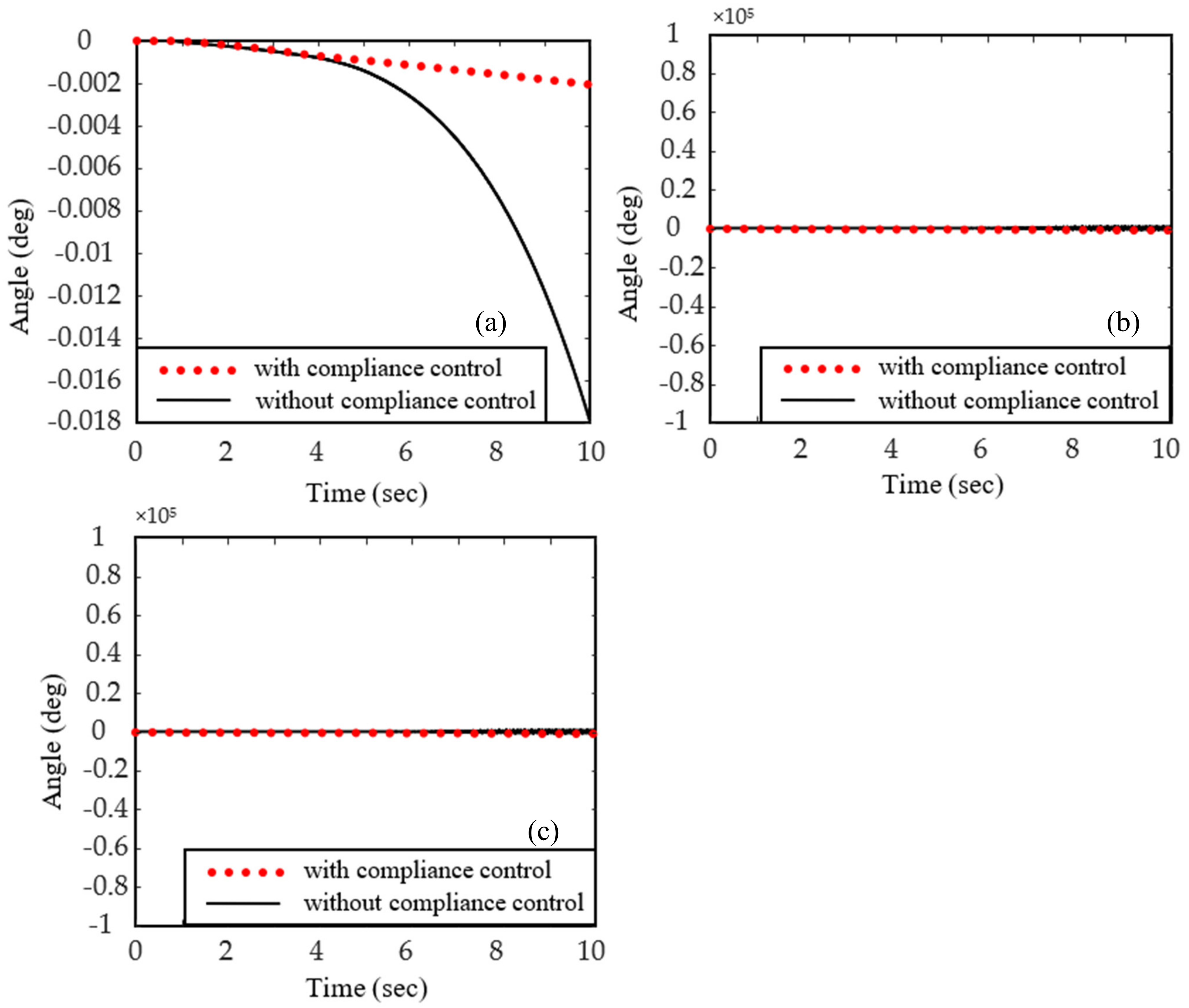
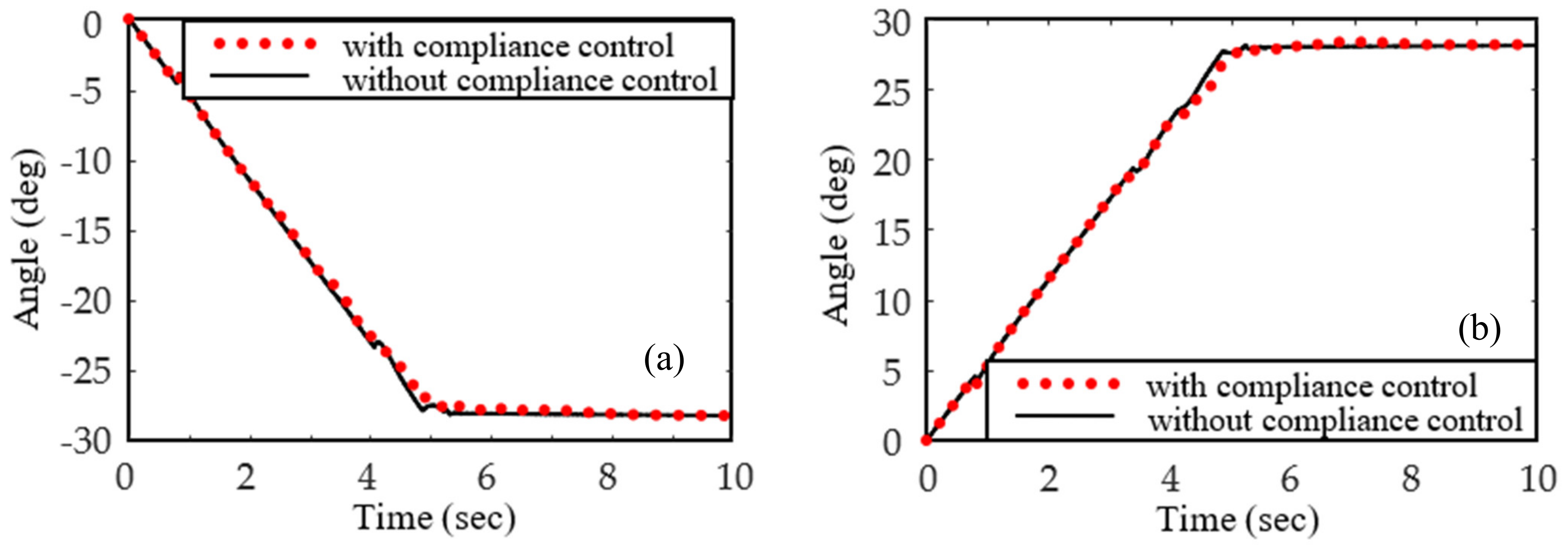
Figure 4 depicts the state of the space robot in the pre-capture and post-capture phases. Figure 5, Figure 6, Figure 7 and Figure 8 present the simulation results for Cases 1 and 2, where Figure 5 and Figure 7 are the time histories of the attitude of the robot base, and Figure 6 and Figure 8 are those of the rotation angle of the hands B6 and B7; the solid line represents the results of Case 1 and the dotted line Case 2. From Figure 5 and Figure 7, it can be observed that capturing operation only causes the plane motion of the robot system and does not produce rotational motions in the Y and Z directions. This is because the space robot is initially in the O-YZ plane, and the middle position of the target is grasped. The change in rotational angle of the robot base around the X-axis using an active compliance controller is smaller than that without using the controller, which demonstrates the effectiveness of the controller in reducing the capture impact on the robot. From Figure 6 and Figure 8, we can observe that the target can finally be firmly grasped for the two cases.
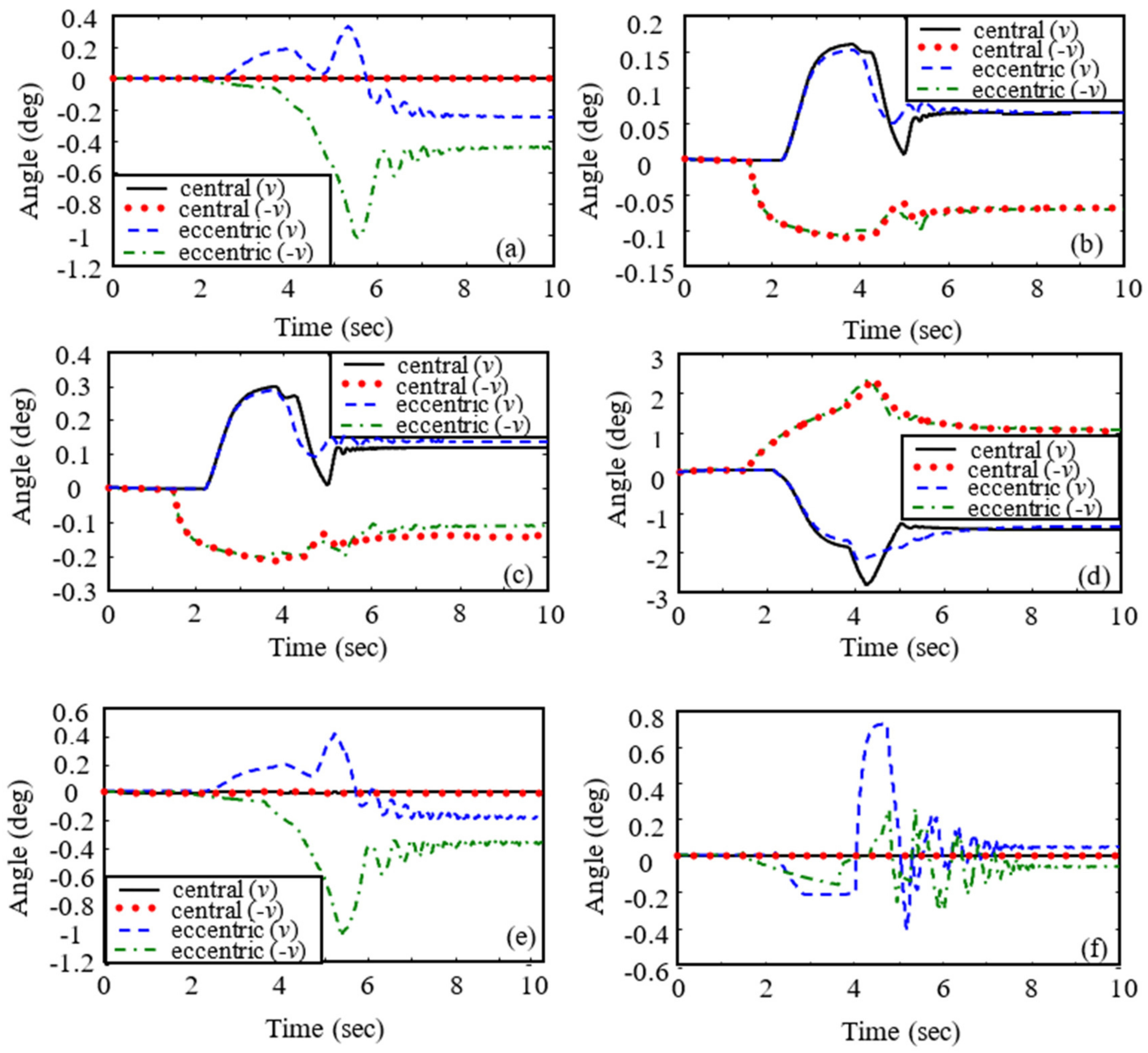
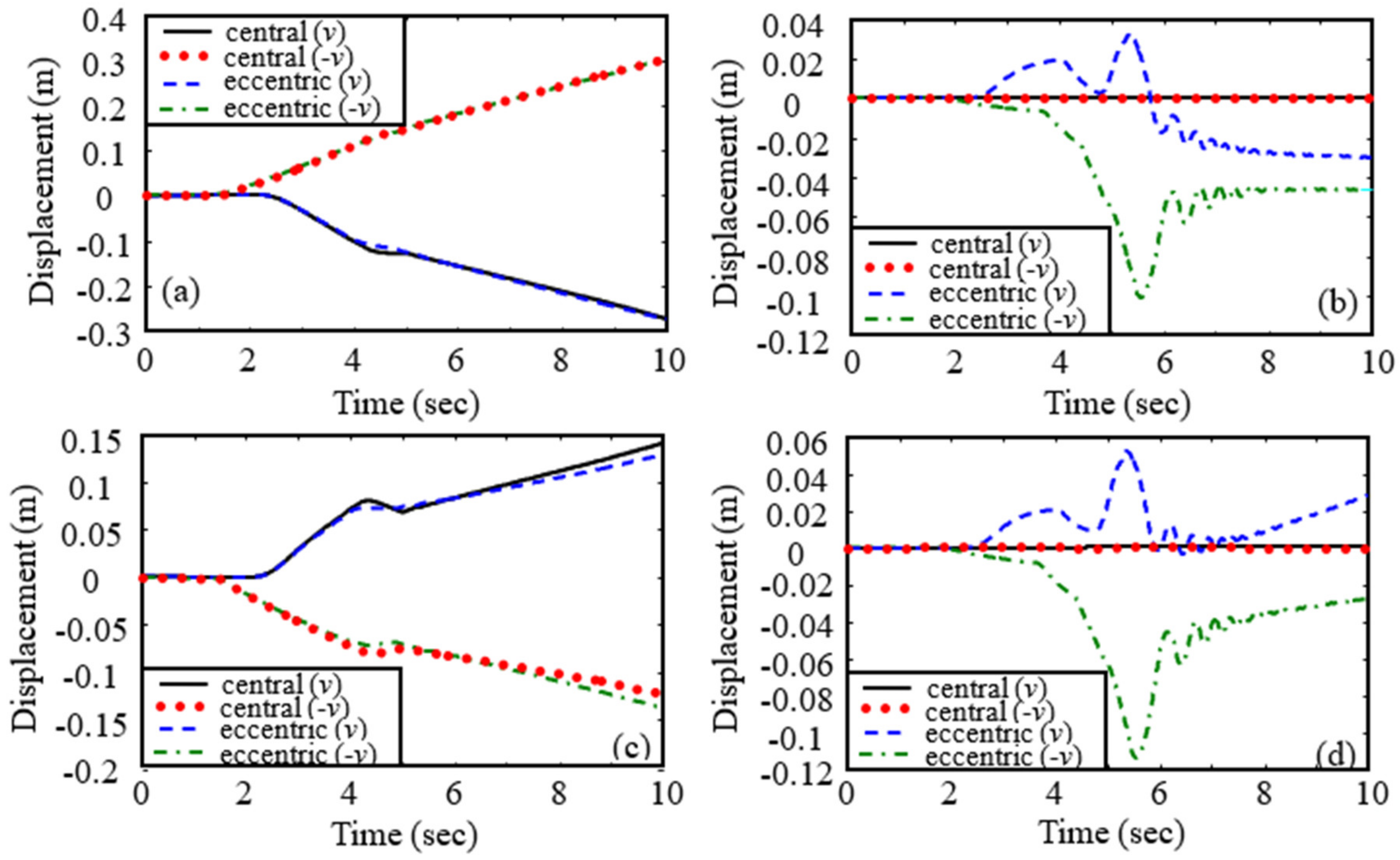
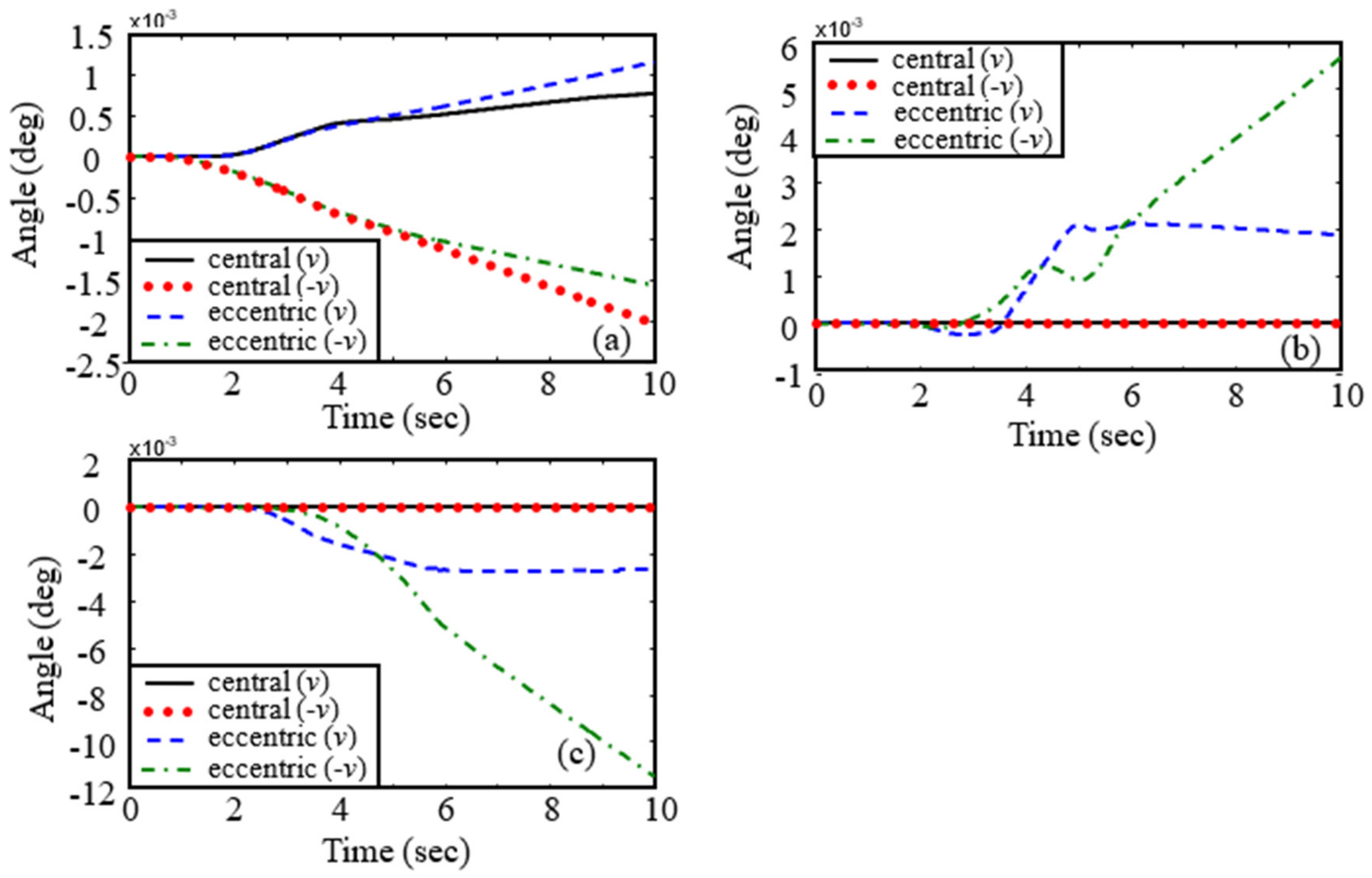
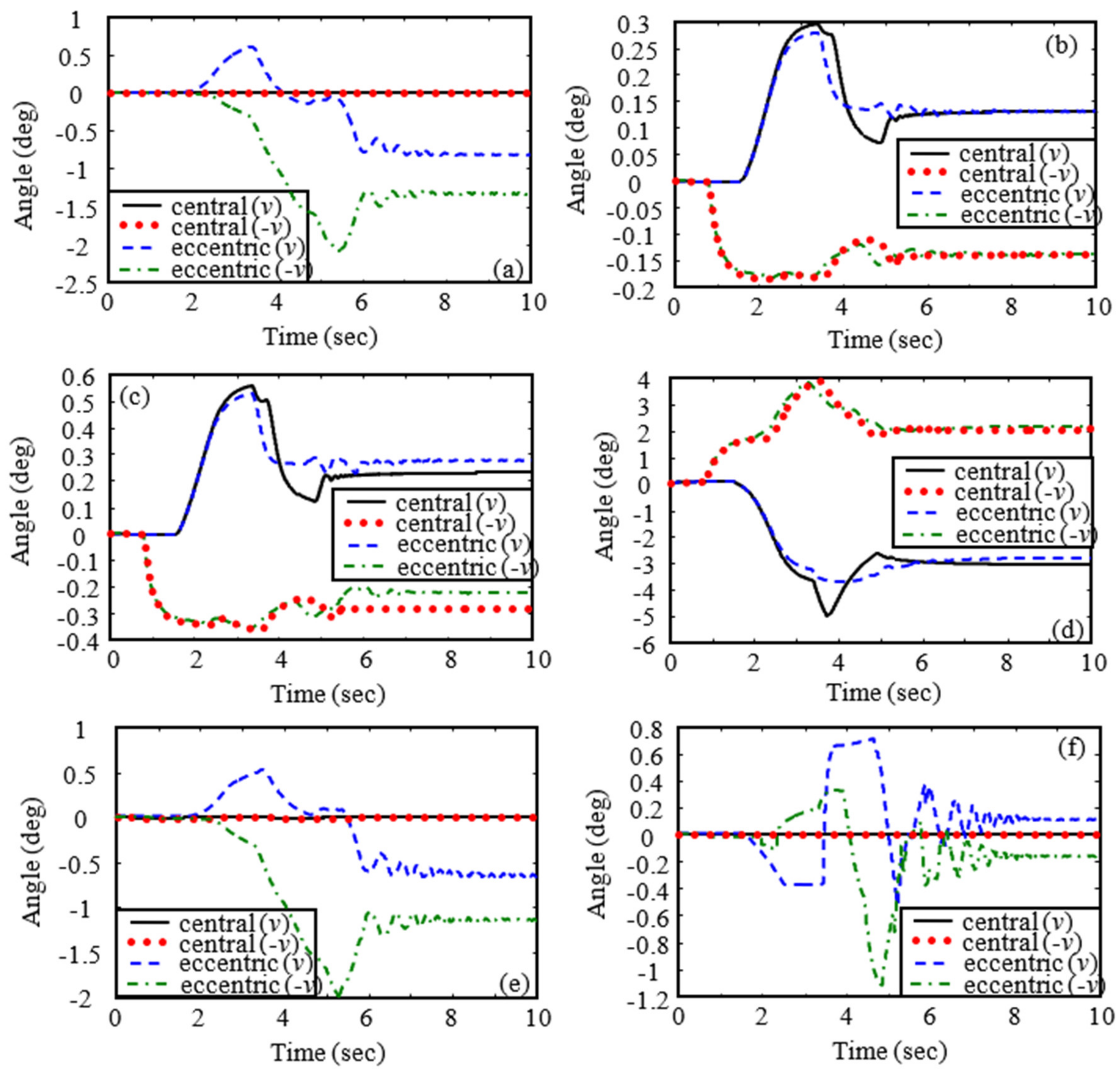
The results above indicate that the active compliance control of the manipulator could effectively reduce the capture impact on the robot. Next, extensive simulations are conducted to further demonstrate the influence of impact. The four impact cases shown in Figure 9 are considered. In these cases, the Y1 and Z1 positions of the mass center of the target cylinder B8 in the O1-X1Y1Z1 frame are 25.05 m and 1 m, respectively, and the cylinder axis parallels the X1 axis. For the first and second impact cases (Figure 8b and Figure 9a), the relative position of the mass center of the target cylinder in the X1 direction is 0 m, and the impact is central impact, and for the third and fourth impact cases (Figure 8d and Figure 9c), the relative position is 0.05 m, and the impact is eccentric impact. In these two cases, the tumbling motion of B8 caused by the capturing operation will appear. Assume that v is the relative velocity between the target cylinder B8 and the end effecter. Two different relative velocities, v = 0.05 m/s and v = 0.1 m/s, are considered in the simulations. The absolute angular velocity of the target cylinder B8 is (0, 0, 0) and the absolute translation velocity of the target cylinder B8 is (0, v m/s, 0) for the first and third impact cases (Figure 9a,c), and they are (0, 0, 0) and (0, −v m/s, 0) for the second and fourth impact cases (Figure 9b,d). In other words, the target cylinder B8 moves at a constant speed v m/s along the Y direction with no rotation towards or away from the robot. The six joints of the manipulator and the two hands B6 and B7 are all controlled in the capturing process. In controller design, K and D are chosen as the same as those in Case 2, namely all elements of K are chosen to be zeros except K25,25 = K26,26 = 200, and D = diag [01×6 100 100 01×6 100 01×6 100 100 100 50 50]. The desired rotational velocities of B6 and B7 are both also 0.1 rad/s. The simulation results are given in Figure 10, Figure 11, Figure 12, Figure 13, Figure 14, Figure 15, Figure 16, Figure 17, Figure 18 and Figure 19, where Figure 10 and Figure 14 are the attitude change of the robot base B1 for v = 0.05 m/s and v = 0.1 m/s, respectively. Figure 11 and Figure 15 are the angular displacement change of the six joints of the robot manipulator, Figure 12 and Figure 16 are the rotation angle change of the two hands of the end effecter, Figure 13 and Figure 17 are the tip responses of the flexible links B2 and B3 in the floating frames O2-X2Y2Z2 and O3-X3Y3Z3. Figure 18 and Figure 19 are the attitude change of the target B8. The conclusions drawn from Figure 10, Figure 11, Figure 12, Figure 13, Figure 14, Figure 15, Figure 16, Figure 17, Figure 18 and Figure 19 are:
(1)
From Figure 10 and Figure 14, we can observe that central impact only causes the attitude change of the robot base B1 in the X direction, but the eccentric impact could cause the attitude change in all directions.
(2)
From Figure 11 and Figure 15, we can observe that the controller designed in this paper can stabilize the motion of joint angles of the manipulator. It is observed from Figure 11a,e,f and Figure 15a,e,f that eccentric impact could cause the joint angle change of the manipulator in the Axis 1, Axis 5, and Axis 6 directions, while central impact could not.
(3)
It is observed from Figure 12 and Figure 16 that the end effecter can successfully capture the target for the four cases.
(4)
From Figure 13 and Figure 17, we can observe that central impact and eccentric impact can both lead to the deformation of the flexible links B2 and B3 in the Y2 and Y3 directions, but only the eccentric impact can lead to the deformation of B2 and B3 in the Z2 and Z3 directions.
(5)
As depicted in Figure 18 and Figure 19, we can observe that eccentric impact causes obvious attitude change of B8, meaning B8 is tumbling, but central impact cannot. Meanwhile, it is observed that the attitude evolution trend is changed several times in eccentric impact cases, which shows that there are multiple instances of contact during capturing. Moreover, it demonstrates that the tumbling motion of the target object makes the capturing operation complicated.
(6)
Figure 10, Figure 11, Figure 12, Figure 13, Figure 14, Figure 15, Figure 16, Figure 17, Figure 18 and Figure 19 show the impact on the robot system caused by capturing when the target cylinder moves towards the manipulator are more significant than those when the target moves away from the manipulator.

6. Concluding Remark

In this paper, the process of capturing a space target using a flexible robot is studied in detail. First, the capture dynamics model is established based on the multi-body dynamics and Hertz contact theories. Then, an active compliance controller is designed to reduce the capture impact on the robot system. We found the presence of dynamic behaviors when using a flexible space robot to capture a non-cooperative target by numerical simulation. The capture impact causes attitude change of the space robot and leads to the deformation of the flexible robotic arm. Comparing different capturing scenarios, the scenario of eccentric impact with negative relative velocity may cause more complex dynamic behavior of the robot than others. So, to reduce the risk, that scenario should be avoided. Furthermore, when the proposed active compliance controller is considered, the capture impact on the robot can be effectively offset.

Author Contributions

Conceptualization, X.-F.L. and X.-Y.Z.; methodology, X.-F.L.; software, X.-F.L. and X.-Y.Z.; validation, X.-F.L. and X.-Y.Z.; formal analysis, X.-F.L. and X.-Y.Z.; investigation, X.-F.L. and X.-Y.Z.; resources, X.-F.L. and X.-Y.Z.; data curation, X.-F.L. and X.-Y.Z.; writing—original draft preparation, X.-F.L. and X.-Y.Z.; writing—review and editing, G.-P.C. and W.-J.C.; visualization, G.-P.C. All authors have read and agreed to the published version of the manuscript.

Funding

Natural Science Foundation of China (grant numbers 11772187, 11802174) and SAST-SJTU advanced space technology joint research fund (grant number USCAST2019-22).

Institutional Review Board Statement

Not applicable.

Informed Consent Statement

Not applicable.

Data Availability Statement

Not applicable.

Acknowledgments

This work was supported by the Natural Science Foundation of China (grant numbers 11772187, 11802174) and SAST-SJTU advanced space technology joint research fund (grant number USCAST2019-22).

Conflicts of Interest

The authors declare no conflict of interest.

References

  1. Fukushima, Y.; Inaba, N.; Oda, M. Capture and berthing experiment of a massive object using ETS7 space robot. In Proceedings of the AIAA Astrodynamics Specialist Conference, Denver, CO, USA, 14–17 August 2000; pp. 635–638. [Google Scholar]
  2. Friend, R.B. Orbital Express program summary and mission overview. In Proceedings of the SPIE Sensors and Systems for Space Applications II, Orlando, FL, USA, 17–18 April 2008; pp. 695801–695803. [Google Scholar]
  3. Van, V.J.; Sharf, I.; Ma, O. Experimental validation of contact dynamics simulation of constrained robotic tasks. Int. J. Robot. Res. 2000, 19, 1203–1217. [Google Scholar]
  4. Wee, L.B.; Walker, M.W. On the dynamics of contact between space robots and configuration control for impact minimization. IEEE Trans. Robot. Autom. 1993, 9, 581–591. [Google Scholar]
  5. Cyril, X.; Jaar, G.J.; Misra, A.K. The effect of payload impact on the dynamics of a space robot. In Proceedings of the IEEE/RSJ International Conference on Intelligent Robots and Systems, Yokohama, Japan, 26–30 July 1993; pp. 2070–2075. [Google Scholar]
  6. Cyril, X.; Misra, A.K.; Ingham, M.; Jaar, G.J. Postcapture dynamics of a spacecraft-manipulator-payload system. J. Guid. Control Dyn. 2000, 23, 95–100. [Google Scholar] [CrossRef]
  7. Yoshida, K.; Sashida, N.; Kurazume, R.; Umetani, Y. Modeling of collision dynamics for space free-floating links with extended generalized inertia tensor. In Proceedings of the IEEE International Conference on Robotics and Automation, Nice, France, 12–14 May 1992; Volume 1, pp. 899–904. [Google Scholar]
  8. Yoshida, K.; Sashida, N. Modeling of impact dynamics and impulse minimization for space robots. In Proceedings of the IEEE/RSJ International Conference on Intelligent Robots and Systems, Yokohama, Japan, 26–30 July 1993; Volume 3, pp. 2064–2069. [Google Scholar]
  9. Yoshida, K.; Mavroidis, C.; Dubowsky, S. Impact dynamics of space long reach manipulator. In Proceedings of the IEEE International Conference on Robotics and Automation, Minneapolis, MN, USA, 22–28 April 1996; pp. 1909–1916. [Google Scholar]
  10. Yoshida, K.; Nakanishi, H. Impedance matching in capturing a satellite by a space robot. In Proceedings of the IEEE/RSJ International Conference on Intelligent Robots and Systems, Las Vegas, NV, USA, 27–31 October 2003; Volume 4, pp. 3059–3064. [Google Scholar]
  11. Yoshida, K.; Nakanishi, H.; Ueno, H.; Inaba, N.; Nishimaki, T.; Oda, M. Dynamics, control and impedance matching for robotic capture of a non-cooperative satellite. Adv. Robot. 2004, 18, 175–198. [Google Scholar] [CrossRef]
  12. Yoshida, K.; Dimitrov, D.; Nakanishi, H. On the capture of tumbling satellite by a space robot. In Proceedings of the IEEE/RSJ International Conference on Intelligent Robots and Systems, Beijing, China, 9–15 October 2006; pp. 4127–4132. [Google Scholar]
  13. Shibli, M.; Aghili, F.; Su, C.-Y. Modeling of a free-flying space robot manipulator in contact with a target satellite. In Proceedings of the IEEE Conference on Control Applications, Toronto, ON, Canada, 28–31 August 2005; pp. 559–564. [Google Scholar]
  14. Shibli, M.; Su, C.-Y.; Aghili, F. Adaptive inverse dynamics control of free-flying space robot contact with a target satellite: A Hubble space telescope case. In Proceedings of the IEEE Canadian Conference on Electrical and Computer Engineering, Ottawa, ON, Canada, 7–10 May 2006; pp. 1275–1278. [Google Scholar]
  15. Matunaga, S.; Kanzawa, T.; Ohkami, Y. Rotational motion-damper for the capture of an uncontrolled floating satellite. Control Eng. Pract. 2001, 9, 199–205. [Google Scholar] [CrossRef]
  16. Uyama, N.; Hirano, D.; Nakanishi, H.; Nagaoka, K.; Yoshida, K. Impedance-based contact control of a free-flying space robot with respect to coefficient of restitution. In Proceedings of the IEEE/SICE International Symposium on System Integration (SII), Kyoto, Japan, 20–22 December 2011; pp. 1196–1201. [Google Scholar]
  17. Uyama, N.; Nakanishi, H.; Nagaoka, K.; Yoshida, K. Impedance-based contact control of a free-flying space robot with a compliant wrist for non-cooperative satellite capture. In Proceedings of the IEEE/RSJ International Conference on Intelligent Robots and Systems, Vilamoura-Algarve, Portugal, 7–12 October 2012; pp. 4477–4482. [Google Scholar]
  18. Thai, C.; Nguyen, H.; Inna, S. Capture of spinning target with space manipulator using magneto rheological damper. In Proceedings of the AIAA Guidance, Navigation, and Control Conference, Toronto, ON, Canada, 2–5 August 2010; p. 7753. [Google Scholar]
  19. Xu, W.F.; Liang, B.; Li, C.; Liu, Y.; Wang, X.Q. A modelling and simulation system of space robot for capturing non-cooperative target. Math. Comp. Model. Dyn. 2009, 15, 371–393. [Google Scholar] [CrossRef]
  20. Xu, W.F.; Meng, D.S.; Chen, Y.Q.; Qian, H.H.; Xu, Y.S. Dynamics modeling and analysis of a flexible-base space robot for capturing large flexible spacecraft. Multibody Syst. Dyn. 2014, 32, 357–401. [Google Scholar] [CrossRef]
  21. Liu, X.-F.; Li, H.-Q.; Chen, Y.-J.; Cai, G.-P.; Wang, X. Dynamics and control of capture of a floating rigid body by a spacecraft robotic arm. Multibody Syst. Dyn. 2015, 33, 315–332. [Google Scholar] [CrossRef]
  22. Yu, Z.-W.; Liu, X.-F.; Cai, G.-P. Dynamics modeling and control of a 6-DOF space robot with flexible panels for capturing a free floating target. Acta Astronaut. 2016, 128, 560–572. [Google Scholar] [CrossRef]
  23. Nishida, S.; Yoshikawa, T. Space debris capture by a joint compliance controlled robot. In Proceedings of the IEEE/ASME International Conference on Advanced Intelligent Mechatronics, Kobe, Japan, 20–24 July 2003; Volume 1, pp. 496–502. [Google Scholar]
  24. Nishida, S.; Yoshikawa, T. Capture and motion braking of space debris by a space robot. In Proceedings of the International Conference on Control, Automation and Systems, Seoul, Korea, 17–20 October 2007; pp. 706–711. [Google Scholar]
  25. Nishida, S.-I.; Kawamoto, S.; Okawa, Y.; Terui, F.; Kitamura, S. Space debris removal system using a small satellite. Acta Astronaut. 2009, 65, 95–102. [Google Scholar] [CrossRef]
  26. Nishida, S.; Kawamoto, S. Strategy for capturing of a tumbling space debris. Acta Astronaut. 2011, 68, 113–120. [Google Scholar] [CrossRef]
  27. Liu, J.; Huang, Q.; Yang, T.; Deng, T. Compliant control of a space robot with multi arms for capturing large tumbling target. In Proceedings of the IEEE International Conference on Mechatronics and Automation, Takamatsu, Japan, 6–9 August 2017; pp. 1859–1864. [Google Scholar]
  28. Liu, X.-F.; Cai, G.-P.; Wang, M.-M.; Chen, W.-J. Contact control for grasping a non-cooperative satellite by a space robot. Multibody Syst. Dyn. 2020, 50, 119–141. [Google Scholar] [CrossRef]
  29. Liu, X.F.; Zhang, X.Y.; Chen, P.C.; Cai, G.P. Hybrid control scheme for grasping a non-cooperative tumbling satellite. IEEE Access 2020, 8, 54963–54978. [Google Scholar] [CrossRef]
  30. Stolfi, A.; Gasbarri, P.; Sabatini, M. A combined impedance-PD approach for controlling a dual-arm space manipulator in the capture of a non-cooperative target. Acta Astronaut. 2017, 139, 243–253. [Google Scholar] [CrossRef]
  31. Stolfi, A.; Gasbarri, P.; Sabatini, M. A parametric analysis of a controlled deployable space manipulator for capturing a non-cooperative flexible satellite. Acta Astronaut. 2018, 148, 317–326. [Google Scholar] [CrossRef]
  32. Zarafshan, P.; Moosavian, S. Fuzzy tuning control approach to perform cooperative object manipulation by a rigid–flexible multibody robot. Multibody Syst. Dyn. 2017, 40, 213–233. [Google Scholar] [CrossRef]
  33. Zarafshan, P.; Larimi, R.; Moosavian, S.; Siciliano, B. Which impedance strategy is the most effective for cooperative object manipulation? Ind. Robot 2017, 44, 198–209. [Google Scholar] [CrossRef]
  34. Liu, X.F.; Li, H.Q.; Wang, J.S.; Cai, G.P. Dynamics analysis of flexible space robot with joint friction. Aerosp. Sci. Technol. 2015, 47, 164–176. [Google Scholar] [CrossRef]
  35. Johnson, K.L. Contact Mechanics; Cambridge University Press: Cambridge, UK, 1984. [Google Scholar]
  36. Ericson, C. Real-Time Collision Detection; Elsevier: Amsterdam, The Netherlands, 2005. [Google Scholar]
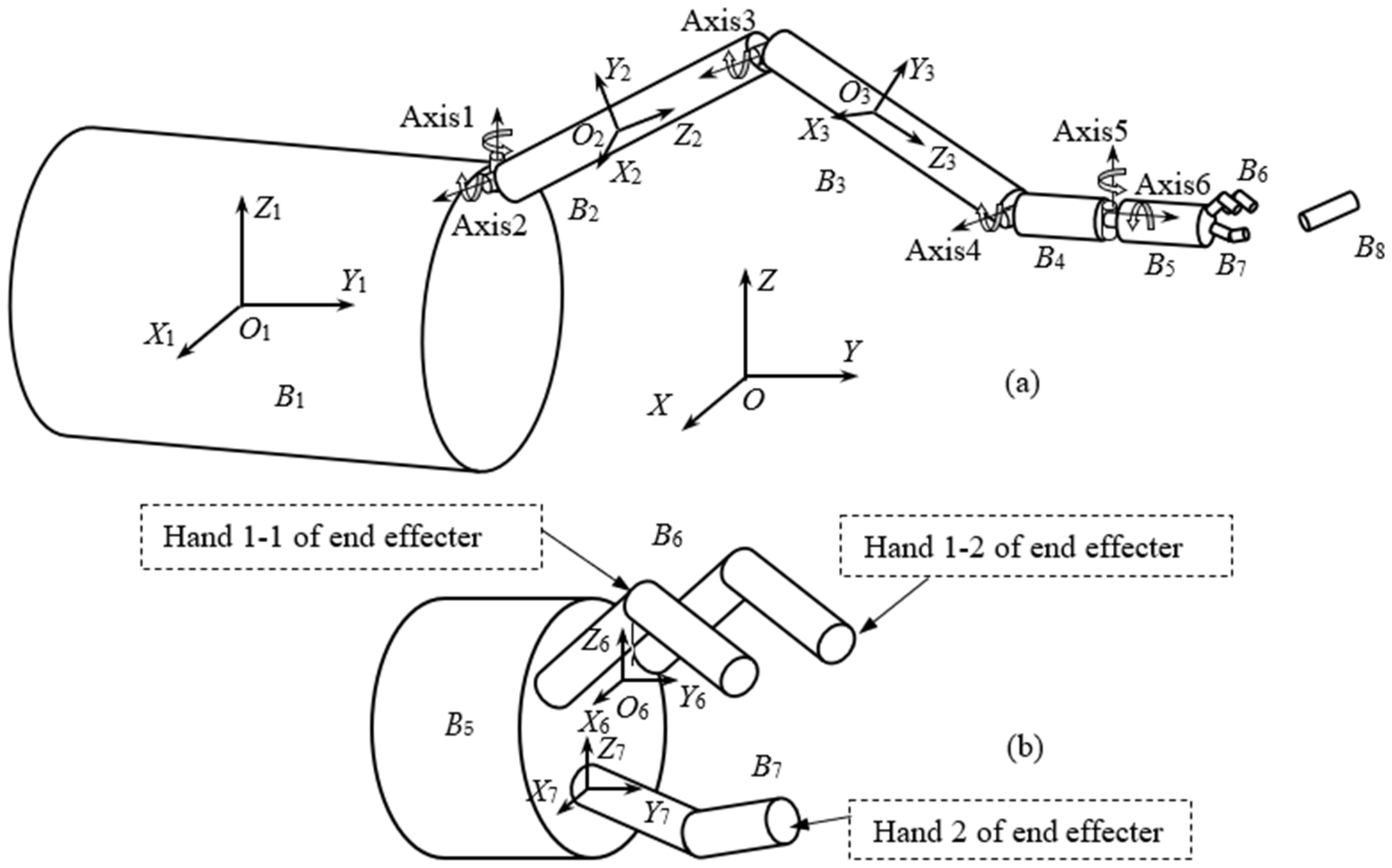
Figure 1. Space robot and the object to be captured: (a) the total diagram of the robot system, and (b) enlarged drawing of the end effecter.
Applsci 12 00984 g001
Figure 2. Schematic diagram of contact detection.
Applsci 12 00984 g002
Figure 3. Positions of the two hands and the captured object: (a) initial position, (b) final position, and (c) grasped position of B8.
Applsci 12 00984 g003
Figure 4. State of the space robot in the process of capturing: (a) pre-capture, and (b) post-capture.
Applsci 12 00984 g004
Figure 5. Time histories of angular displacement of the robot base B1 with and without active compliance control of the manipulator (0.05m/s): (a) the X axis, (b) the Y axis, and (c) the Z axis.
Applsci 12 00984 g005
Figure 6. Time histories of rotation angle of the two hands B6 and B7 with and without active compliance control of the manipulator (0.05 m/s): (a) B6, and (b) B7.
Applsci 12 00984 g006
Figure 7. Time histories of angular displacement of the robot base B1 with and without active compliance control of the manipulator (0.1 m/s): (a) the X axis, (b) the Y axis, and (c) the Z axis.
Applsci 12 00984 g007
Figure 8. Time histories of rotation angle of the two hands B6 and B7 with and without active compliance control of the manipulator (0.1 m/s): (a) B6, and (b) B7.
Applsci 12 00984 g008
Figure 9. Four impact cases.
Applsci 12 00984 g009
Figure 10. Time histories of angular displacements of the robot base B1 (v = 0.05 m/s): (a) the X axis, (b) the Y axis, and (c) the Z axis.
Applsci 12 00984 g010
Figure 11. Time histories of angular displacements of the manipulator (v = 0.05 m/s): (a) Axis 1, (b) Axis 2, (c) Axis 3, (d) Axis 4, (e) Axis 5, and (f) Axis 6.
Applsci 12 00984 g011
Figure 12. Time histories of the rotation angles of the two hands (v = 0.05 m/s): (a) B6, (b) B7.
Applsci 12 00984 g012
Figure 13. Tip displacements of the flexible links B2 and B3 (v = 0.05 m/s): (a) B2 in the Y2 direction, (b) B2 in the Z2 direction, (c) B3 in the Y3 direction, and (d) B3 in the Z3 direction.
Applsci 12 00984 g013
Figure 14. Time histories of angular displacements of the robot base B1 (v = 0.1 m/s): (a) the X axis, (b) the Y axis, and (c) the Z axis.
Applsci 12 00984 g014
Figure 15. Time histories of angular displacements of the manipulator (v = 0.1 m/s): (a) Axis 1, (b) Axis 2, (c) Axis 3, (d) Axis 4, (e) Axis 5, and (f) Axis 6.
Applsci 12 00984 g015
Figure 16. Time histories of the rotation angles of the two hands (v = 0.1 m/s): (a) B6, and (b) B7.
Applsci 12 00984 g016
Figure 17. Tip displacements of the flexible links B2 and B3 (v = 0.1 m/s): (a) B2 in the Y2 direction, (b) B2 in the Z2 direction, (c) B3 in the Y3 direction, and (d) B3 in the Z3 direction.
Applsci 12 00984 g017
Figure 18. Time histories of angular displacements of the target B8: (a) v = 0.05m/s, (b) v = 0.05 m/s, (c) v = −0.05 m/s, and (d) v = −0.05 m/s.
Applsci 12 00984 g018
Figure 19. Time histories of angular displacements of the target B8: (a) v = 0.1 m/s, (b) v = 0.1 m/s, (c) v = −0.1 m/s, and (d) v = −0.1 m/s.
Applsci 12 00984 g019
Table 1. Physical parameters of the space robot.
BodyMass (kg)Ixx (kg·m2)Iyy (kg·m2)Izz (kg·m2)EI (N·m2)GJ (N·m2)EA (N)
B11.0179 × 1055.0894 × 1064.9113 × 1064.9113 × 106
B21380.399471.82471.824.04 × 1062.040 × 1062.8 × 109
B385.060.4348.01348.012.81 × 1061.417 × 1061.2 × 109
B480.20.760.76
B5410.25.025.02
B612.250.1630.1360.2759
B76.1250.0820.00680.0767
B8480.351.180.70.7
Publisher’s Note: MDPI stays neutral with regard to jurisdictional claims in published maps and institutional affiliations.