Abstract
Currently, a significant trend in control in robotic systems is developing and improving linear and nonlinear control algorithms to improve the overall quality of production with high accuracy and adaptability. The present study considers a synergistic synthesis of throttle control of a pneumatic distributor valve and backpressure control for piston rod positioning. The article presents the synthesis of control laws for the position of a pneumatic cylinder piston using the method of analytical design of aggregated regulators (ADAR) of synergetic control theory (STC), which allows operation with nonlinear mathematical models, eliminating the loss of information about the object during linearization. A comparative calculation of the energy efficiency of backpressure control and throttle control methods was carried out, while the numerical value of the total airflow with throttle control is 0.0569 m3⁄s and, with backpressure control, it is 0.0337 m3⁄s. Using a P controller in a linear model gives a transient oscillatory process damped in 2–2.5 s. When using a PID controller, the process has an overshoot equal to 11.5%, while the synergistic controller allows you to smoothly move the drive stem to a given position without overshoot. The parametric uncertainty analysis of the considered mathematical model is carried out. The model’s main parameters are identified, which change the actual functioning of the system under study. The inconsistency of applying classical control laws based on typical controllers to parametrically indeterminate mathematical models is shown.
1. Introduction
In recent years, an important trend in control in robotic systems has been developing and improving algorithms for linear and nonlinear control to enhance the overall quality of production with high accuracy and high adaptability [1,2,3]. At present, the technological relevance of controlling an electro-pneumatic system (EPS) is associated with accurate and smooth braking of the pneumatic drive piston in each co-ordinate of its trajectory in various operating modes of the system under conditions of disturbing external factors.
To achieve control goals, linear and nonlinear automatic control theory methods are used, including intelligent algorithms for constructing fuzzy controllers. At the same time, there are difficulties associated with the need to consider external disturbances and changes in the parameters of the dynamic model described by nonlinear differential equations.
The analysis showed [4,5,6] that, when synthesizing algorithms for controlling pneumatic systems, the developer is faced with a rather complex analytical description of thermodynamic processes associated with the nonlinear movement of air passing through the holes of the pneumatic distributor. To simplify mathematical models, these assumptions are used to linearize “inconvenient” nonlinear dependencies [7,8], reduce the system dimension, and introduce additional correction factors and further research of the linear pneumatic system.
For a modern, accurate control of the pneumatic system, it is impractical to use a linear model with a reduced order of the system of equations, and the use of PID controllers in linearized models with significant nonlinearity, to which the pneumatic system belongs, leads to difficulties in choosing the parameters of the controller and, consequently, their limited efficiency. The solution to this problem is a scientific problem [9,10,11] associated with the construction of new models of automatic control.
1.1. Fuzzy Adaptive Control
In recent decades, the development of microprocessor technology has led to improvement of regulator tuning algorithms. Now, there are industrial controllers with automatic tuning of the parameters of mobile robotic systems using adaptive algorithms, neural networks, fuzzy logic methods, and genetic algorithms [12,13,14,15].
In [16], a path-tracking controller with geometric constraints and built-in intelligence for collision avoidance was proposed based on a dual hybrid control law. The hybrid control law combines a linearization feedback controller with a fuzzy logic controller. The feedback linearization controller helps the mobile robot stay on the target path, and the fuzzy logic controller helps the mobile robot avoid critical obstacles on the reference path.
Due to intractable errors in approximating nonlinear dependencies, existing controllers may receive only limited results and require speed feedback to perform an online estimate. To overcome the drawbacks, in [17], a new controller with output feedback was developed to accurately track the trajectory and obtain state estimates for the class of Euler–Lagrange mechatronic systems. Firstly, a group of auxiliary variables was created to reconstruct velocities without numerical differential operations accurately. Then, unknown model information and dead zones/drive faults are simultaneously approximated online using only the available output information.
The authors of [18] propose a fuzzy control method for undefined nonlinearity, unknown modeling parameters, and an inaccessible state. First, an interval fuzzy logic system type 2 (IT2 FLS) and a state observer based on the IT2 FLS are created to estimate the systems’ uncertain nonlinearity and unavailable state. A target performance control (PPC) method is then proposed to achieve the target tracking characteristics of steer-by-wire (SbW) systems.
A hypersonic apparatus is considered in [19] as a typical nonlinear and indefinite model, which has parameters and characteristics of strong coupling that change rapidly over time. The authors proposed an adaptive method for compensating unknown disturbances of the aircraft model in real time and improving control characteristics by developing a nonlinear control law. The tracking differentiator smoothly tracks the manipulated variable error, and an extended state observer is created based on the unknown disturbances to perform a single real-time estimate. The nonlinear controller improves control efficiency and allows the controlled object to quickly and stably track the trajectory. Simulation results for a hypersonic vehicle controller demonstrate that fuzzy ADRC (FADRC) has an advantage in tracking speed and effect over traditional methods and simplifies the ADRC parameter design process.
Active noise cancellation control (ANCC) is used in attitude control of a quadcopter to solve the problem of destabilization in flight control [20]. The authors proposed an algorithm for fractional optimization of a swarm of fuzzy particles to optimize ANCC parameters for quadcopters. In addition, a turbulent airflow model has been created to test the effectiveness of the suppression of disturbances by the controller. After optimizing the parameters with the proposed algorithm, the results show that the regulator has a small overshoot and a stronger interference suppression ability.
The disadvantages of controllers based on fuzzy logic include: the impossibility of mathematical analysis of fuzzy systems using existing methods, a slight increase in accuracy compared to the probabilistic approach, and increasing the number of input variables increases the computational complexity exponentially, making it difficult to comprehend.
1.2. Neural Network Control
Intelligent control of dynamic systems by means of neuro regulators is widely used [21,22,23,24,25]. In a neuro regulator, the neural network acts as a regulator covered by negative feedback.
A fail-safe method for controlling the flight of a multi-rotor uncrewed aerial vehicle (UAV) in the event of an actuator failure and external wind disturbances was proposed in [26]. The control method is based on ANCC and space–time neural networks with a radial basis function, which can be used to achieve stable control of the system when the parameters of the UAV mathematical model change. The new radial basis function neural network outputs are used to estimate fusion parameters containing actuator malfunctions and model uncertainties to design an active fault-tolerant controller for a multi-rotor vehicle.
A method for improving autonomous maneuvering of an autonomous underwater vehicle (AUV) with four degrees of freedom (4DOF) for trajectory tracking tasks in a disturbed underwater environment is presented in [27]. In this study, four input-affine nonlinear equations of the second order are considered for the translational (x, y, z) and rotational (course) dynamics of a real AUV, considering the uncertainties of the hydrodynamic parameters. The authors proposed the dynamic neural control system (DNCS) control scheme as a combination of an adaptive neural controller based on a nonparametric identification of the influence of unknown dynamics and a parametric estimate of the added gain dependent on mass.
The development of vehicle stability controllers based on the nonlinearity and uncertainty of external disturbance parameters was carried out in [28]. An adaptive two-layer Kalman filter is used to calculate the sideslip angle, and an algorithm for controlling the stability of a vehicle with an adaptive fuzzy radial basis of a neural network for slip mode control is proposed. The proposed models are actively used in mechanical engineering and other industries [29,30,31].
In the neural network approach, as in the case of control based on fuzzy logic, there is a need to access a large amount of data for training and assess the complexity of the mathematical analysis of the selected controller structure.
1.3. Adaptive and Robust Control
The task of synthesizing effective control laws with adaptive properties to external disturbances is quite relevant. This is confirmed by a large number of scientific papers devoted to the development of various methods for adaptive and robust control of a pneumatic actuator. Methods of classical control based on typical linear controllers as applied to parametrically uncertain models show unsatisfactory results. Therefore, unique robust and adaptive control methods are used to study models with undefined parameters under conditions of external disturbances [32,33,34,35,36].
In [37], an optimal adaptive control approach is established for solving robust control problems for nonlinear systems with internal and input uncertainties. First, the robust control is transformed into an optimal control solution containing a nominal or auxiliary system with a predetermined efficiency index. Then, based on Bellman’s principle of optimality, online algorithms are proposed for calculating robust controllers for consistent and noncoincident non-defined systems. It is shown that the optimal control law ensures the global asymptotic stability of the system under consideration under all admissible uncertainties.
A robust adaptive control strategy for synchronizing a class of uncertain chaotic systems with unknown time delays was proposed in [38]. Based on the proposed adaptation rules, an adaptive controller has been developed for stable synchronization of uncertain systems, which proves the robust stability of the proposed control mechanism using the Lyapunov theorem.
In this paper, we consider the synthesis of nonlinear synergistic laws for controlling the position of the pneumatic drive piston. Synthesis of control laws is carried out using the ADAR STC method. One of the indisputable advantages of the ADAR STC method is that, in the synthesis of the control law, an initially nonlinear model is used, which most fully describes the processes in the system compared to linearized models, which are often tested in many other works discussed above.
2. Methods
The concept of synergetic control theory (SCT) is based on the method of analytical design of aggregated controllers (ADAR), which allows control laws to be synthesized in an analytical form for nonlinear, multidimensional, multi-connected objects, which include an electro-pneumatic system (EPS) [39].
This paper presents a synthesis of the laws for controlling the position of the piston of a pneumatic cylinder using the synergistic method of the ADAR, which considers the system’s nonlinear dynamics under consideration.
The procedure for the synthesis of synergistic control is based on the introduction of a sequence of invariant manifolds, based on the technological problem of positioning the pneumatic cylinder rod at the required position, and the subsequent step-by-step decomposition of the original dynamic system.
2.1. Formulation of the Control Problem for EPS and Methods of Its Implementation
The investigated dynamic system is a nonlinear dissipative system. Namely, in such systems, the properties of self-organization of movement are manifested due to the presence of attractors in their phase space.
One of the initial stages of the synthesis of the control law (CC) according to the ADAR method is the selection of control objectives invariants that are set based on the technological problem, taking into account the physical essence of the dynamics of the processes occurring in the system under study [40]. Since the considered EPS is described by the equations of the dynamics of the piston motion and the equations of thermodynamic equilibrium, it is necessary to set technological and thermodynamic invariants, which will be the final goal of the state of the system. According to the task of control, pneumatic drives are divided into positional and tracking; thus, the ultimate goal of control technological invariants can be positioning the co-ordinate of the piston l to a given position, as well as changing the speed of the piston V according to a given time law.
Thermodynamic invariants should reflect the “internal” balance of forces of the system, which will ensure the fulfillment of the final technological control task. Similar forces in the system under study are the pressure of compressed air in the filling chamber p1, which is essentially the “working” pressure affecting the movement of the piston, as well as the pressure in the exhaust chamber p2, a change that affects the deceleration of the piston and, consequently, its speed movement. Thus, a systemic control model is traced, in which the equilibrium of the system state variables will correspond to certain control objectives.
According to the ADAR method, the number of control channels must correspond to the number of specified target functions. Control in the EPS is carried out through two channels:
- -
- Control of the incoming mass air flow, which forms the pressure p1 in the filling chamber, is carried out by changing the cross-sectional area f1 of the pneumatic distributor valve PR1;
- -
- Control of the mass flow rate of air leaving the exhaust chamber, which is physically reflected in the form of pressure p2, is carried out by changing the cross-sectional area f2 of the PR2 valve.
In industrial pneumatic automation, two methods of controlling pneumatic drives [40] have been patented, which, in their essence, consist of the method of braking the piston at the end of the working stroke: these are throttle control and backpressure control.
2.2. Procedure for Synergistic Synthesis of Nonlinear Laws of Throttle Control of EPS
In the EPS, the generated pressure p1 in the filling chamber is responsible for the starting and further movement of the piston, and the increase in pressure p2 in the exhaust chamber decelerates the piston. With throttle control, the piston is decelerated in a given position by regulating the pressure p2 of the airflow leaving the exhaust chamber of the pneumatic cylinder by correspondingly changing the cross-sectional area of the PR2 valve.
The main task of control is that it is necessary to synthesize such control actions that provide specific ratios of pressures p1 and p2, at which the piston of the pneumatic cylinder makes a smooth stop at a given position l.
Before proceeding to the procedure for the synthesis of control laws by the ADAR method, it is necessary to designate the state variables of the system under study and control actions as follows: x1 = l; x2 = V; x3 = p1; x4 = p2; f1 = U1f; f2 = U2f.
Moreover, for a more compact representation of the mathematical model of the EPS and further ergonomic mathematical transformations, the following coefficients are introduced: ; ; , where R—specific gas constant (for dry air R = 287 J/(kg × K); k = 1.4—adiabatic exponent for air; TM = 290 K—line temperature; S1 and S2—areas of rodless and rod surfaces, respectively; pa—atmospheric pressure acting on the end surface of the rod; M—the mass of the moving part of the piston and rod; η—kinematic coefficient of viscous friction; L—piston stroke length; l01, l02—start and end co-ordinates of the piston location; ξ—throttle resistance coefficient in the cylinder cavity.
After the designations and coefficients defining and the transformation, mathematical modeling of the EPS (MM EPS) will look like this:
Based on the previous, let us formulate the control problem as follows. First, it is necessary to carry out two-channel control of the position of the piston x1 by changing the pressures in the filling chamber x3 and the exhaust chamber x4 of the pneumatic drive using the control actions U1f and U2f, which are the areas of flow areas PR1 and PR2.
From the STC point of view, this equation means that it is necessary to synthesize a vector of control actions U1f (x1, x2, x3, x4) and U2f (x1, x2, x3, x4) as a function of phase co-ordinates, which would transfer the representing point (RP) of the system from the initial state to the required final state, provided that the required quality criteria are met.
According to the technological task of positioning the pneumatic cylinder rod at the required position formulated in Section 2.1, we introduce the first in-option corresponding to the control goal:
where x1—the current position of the bar, x1*—required value.
The second invariant of the system is assumed to be the condition:
corresponding to the problem of pressure stabilization in the exhaust chamber, where x4* is a given value of pressure p2.
Proceeding from the fact that a change in the flow area U1f (xn) on PR1 affects the dynamics of pressure change in the filling chamber x3, and a change in the flow area U2f (xn) on PR2 affects the dynamics of pressure change in the exhaust chamber x4, it is advisable to introduce the following collection of invariant varieties:
The second manifold contains some function φ1(x1, x2), which determines the desired character of the pressure change x3 at the intersection of the invariant manifolds ψ1 = 0 and ψ2 = 0. The function φ1(x1, x2) is determined during the synthesis of control laws based on conditions for the fulfillment of invariant (2).
According to the ADAR method, the macro variables ψ1 and ψ2 must satisfy the solution of the system of basic functional equations:
where T1 > 0 and T2 > 0 provide the conditions for the asymptotic stability of the motion of the system.
When the RP system hits the intersection of the manifolds ψ1 = ψ2 = 0, an exact dynamic decomposition of the system (1) occurs, and the equations describe the dynamics of the closed-loop system:
The function φ1(x1, x2), in the decomposed system (6), can be considered as an “internal” control that directly affects the movement and speed of the rod.
At the second synthesis stage, to search for control and, therefore, the definition of the function φ1(x1, x2), an additional invariant manifold is introduced, which should ensure the stability of the closed-loop system and the fulfillment of the technological invariant (2). Based on this, we introduce the manifold:
The following equation describes the dynamics of the system on this manifold:
the stability condition of which, with respect to x1 = x1*, is the inequality k < 0.
For the condition ψ3 = 0 to be fulfilled, the macro variable ψ3 must satisfy the solution of the functional equation:
where T3 > 0 is the condition of asymptotic stability of the motion of the representing point of the system to the invariant manifold.
Substitute (7) into (9) to define the internal control φ1:
Further, the equations of the decomposed system (6) are substituted into Equation (10), as a result of which the following expression is obtained:
Let us express the internal control φ1 from the expression (11):
The desired control law is found as a joint solution of the system of Equations (5), (6), and (12) and has the following form:
where pm—line pressure value.
The time constants T1, T2, and T3 included in the control actions (13) and (14) reflect the dynamics of the system’s motion in the phase space.
To analyze the behavior of a closed-loop system, taking into account the control law obtained in an analytical form, a computer simulation of the system was carried out in the Maple package using the Runge–Kutta numerical solver.
In this simulation, the Camozzi pneumatic cylinder parameters were used, the characteristics of which are summarized in Table 1.

Table 1.
Parameters of the simulated EPS.
Figure 1, Figure 2, Figure 3 and Figure 4 show the results of the numerical solution of the system of differential equations (DE) with control laws (13) and (14) in the Maple package environment for the given initial conditions of the system: x1 = 0 m; x2 = 0 m/s; x3 = 105 Pa; x4 = 105 Pa, and the desired values of piston displacement x1* = 0.1 m and pressure in the exhaust chamber x4*=1.25 Pa.
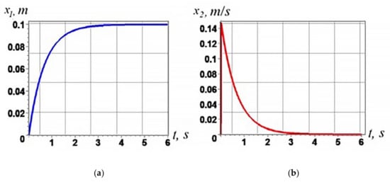
Figure 1.
Graphs of changes in the phase variables of the EPS: (a) piston displacement; (b) piston speeds.
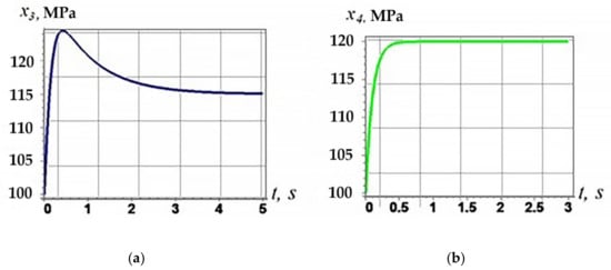
Figure 2.
Graphs of changes in the phase variables of the EPS: (a) change in the pressure in the inlet chamber; (b) change in pressure in the exhaust chamber.
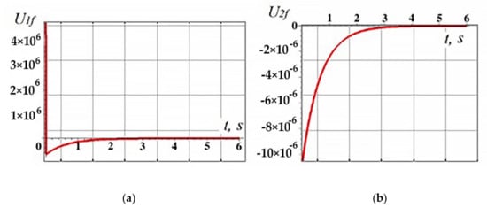
Figure 3.
Diagrams of transient processes during throttle control: (a) control action PR1; (b) control action PR2.
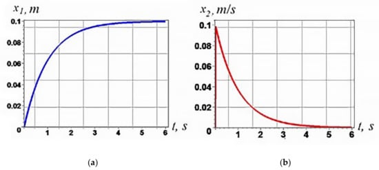
Figure 4.
Graphs of changes in the phase variables of the EPS with co-ordinated control: (a) piston displacement; (b) piston speeds.
According to the graphs of transient processes shown in Figure 1, it can be seen that the position of the rod reaches the desired value of displacement in a time of 3 s (Figure 1a), which indicates the adequacy of the synthesized memory device, as well as its asymptotic stability. The graph of the change in the speed of the pneumatic cylinder rod (Figure 1b) shows that the speed, increasing to a maximum at the beginning of the movement of the pneumatic cylinder, decreases, taking on a zero value when a given displacement is reached.
The graphs of the pressure change in the filling chamber and in the exhaust chamber are shown in Figure 2. It can be seen from the graphs that the process of piston movement is accompanied by a natural change in the volumes of the cavities of the pneumatic cylinder. The pressure in the filling chamber increases rapidly at the initial moment of time (Figure 2a). Then, the pressure decreases due to the increase in the volume of the filling chamber due to the piston movement. The pressure in the exhaust chamber reaches the desired value x4* (Figure 2b), while the pressure x4 at the end of the piston stroke cycle is slightly higher than the pressure x3, which is explained by the smaller volume of the exhaust chamber due to the presence of the piston rod within it.
Figure 3 shows graphs of the laws of control of valves of pneumatic control valves PR1 and PR2. At the initial moment of time, all PR holes are closed, which corresponds to a zero value of the control action. PR1, located on the inlet line, is connected to the compressed air power source. When the valve is opened (Figure 3a), a portion of compressed air enters the filling chamber; this happens in a fraction of a second, then the valve closes completely in 2 s. The exhaust valve PR2 is fully open (Figure 3b), which allows the exhaust air to be discharged into the atmosphere. The PR2 valve closes gradually when the piston reaches the preset position.
Thus, negative values of control actions indicate the release of compressed air into the atmosphere, and positive values indicate the connection of the valve with the supply line.
The results of modeling a closed-loop system with the obtained synergistic memory devices show the asymptotic stability of the dynamics of the system, as well as the achievement of control goals, which are the movement of the pneumatic cylinder rod to a given position and the maintenance of pressure in the exhaust chamber.
As can be seen from the above simulation, in the throttle control, the piston is decelerated due to excess pressure in the exhaust chamber, which is achieved due to a corresponding decrease in the control action of the PR2 valve.
This control method is quite simple to implement technically. However, in practical use, the disadvantages of throttle control were identified, including energy losses associated with the consumption of a large amount of compressed air to create excess pressure in the chambers of the pneumatic cylinder.
In this case, compressed air under pressure leads to an increase in the temperature of the chambers of the pneumatic drive. As a result, the body and internal components are heated, which negatively affects the functional properties of the EPS.
Therefore, in practice, another control method is more often used, in which, after acceleration of the piston, compressed air is supplied to the exhaust chamber by connecting the PR2 to the power source. Thus, a smooth, uniform change in pressure in the chambers of the pneumatic drive is achieved, leading to lower consumption of compressed air and reduced energy losses.
In this regard, it is advisable to consider the synthesis of nonlinear synergistic laws of backpressure control to position the pneumatic actuator piston, which is presented in the next paragraph of this study.
2.3. Synthesis of Nonlinear Synergistic Laws of Control of EPS Backpressure
In the given variant of the throttle control synthesis, separate pressure control in the pneumatic cylinder chambers is provided; the pressure in the filling chamber p1 is directly responsible for the positioning of the rod x1, and the pressure in the exhaust chamber p2 is stabilized at a certain preset value x4*.
At the same time, the control channel U1f remains “passive” in solving the technological problem. In addition, the stabilized pressure in the exhaust chamber p2, as mentioned above in Section 2.2, may be excessive or insufficient, which leads to additional energy costs for maintaining it.
Co-ordinated control, the purpose of which will be to stabilize the pressures, is carried out by supplying compressed air to the exhaust chamber. In contrast, the exhaust air from the exhaust chamber will not escape into the atmosphere. Still, such a pneumatic cylinder control is called backpressure control in an environment with increased pressure.
When the drive comes to a complete stop, the pressures in the inlet and outlet chambers will be equal to each other, respectively. Thus, during the movement of the rod, the pressure is equalized. It is possible to reflect this alignment by the corresponding invariant manifolds during the synergistic synthesis procedure. In the meantime, to ensure this condition, it is necessary to introduce invariant (3) of the following form:
Then, the set of introduced invariant manifolds takes the form:
Moreover, the manifolds must satisfy the functional equations:
When the system hits the introduced manifolds (16), the decomposed DE system takes the form:
where φ1 (x1, x2)—internal control.
To find the internal control φ1, a manifold is introduced that is responsible for the motion of the system on the attractor:
For the asymptotically stable motion of the system on the attractor to the control goal x1 = x1*, (19) must satisfy the functional equation:
The joint solution of the functional Equation (20) and the introduced manifold (19), considering the decomposed system (18), allows us to find the internal control:
Further, substituting (21) into the second manifold (16) and solving together with functional Equations (17) and model (1), we obtain the valve control law on PR1:
where:
and, also, the law of control of the valve on PR2:
where:
Figure 4, Figure 5, Figure 6 and Figure 7 show the results of modeling the system with the obtained synergistic memory devices (22) and (23) in the Maple package environment, under similar initial conditions of the system (Section 2.2) and the desired values of piston displacement x1* = 0.1 m and pressure in exhaust chamber x4 = x3 = 105 Pa. The following controller parameters have been set: T1 = T2 = 0.1; T3 = 1 s, k = –5.5.
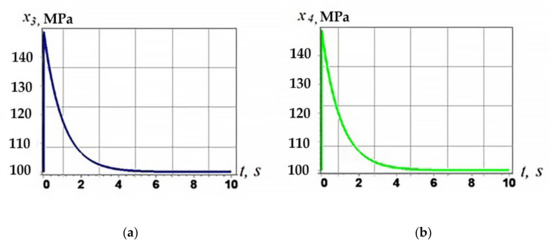
Figure 5.
Graphs of changes in the phase variables of the EPS: (a) change in the pressure in the inlet chamber; (b) change in pressure in the exhaust chamber.
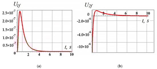
Figure 6.
Transient graphs for co-ordinated control: (a) control action PR1; (b) control action PR2.
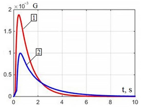
Figure 7.
Airflow dependencies: 1—throttle control; 2—backpressure control.
Comparative analysis of the graphs of transient processes presented in Figure 1 and Figure 4 shows that the movement of the rod with co-ordinated control takes a second longer (Figure 4a), while the rod speed decreases (Figure 4b). This fact is related to the time required to equilibrate the pressures. The graphs of the pressure changes in the intake and exhaust chambers are shown in Figure 5.
PR1 operates in the chamber filling mode. Its port is connected to the power supply. A positive control value (Figure 6a) corresponds to the opening of the compressed air inlet port. At the initial moment, PR2 operates at the outlet of compressed air from the chamber (Figure 6b), which corresponds to negative values of the control actions; then, the PR2 port is connected to the compressed air supply line and the discharge pressure enters the exhaust chamber, which allows smooth stabilizing of the pressures in the filling chambers and exhaust to atmospheric value.
From the simulation results with co-ordinated control of the backpressure, in order to balance the pressures in the chambers of the pneumatic cylinder, the following conclusions can be drawn: the time to reach the set value of the rod movement increases, which is associated with the process of pressure stabilization.
This backpressure control is often used in pneumatic automation due to the possibility of smooth movement of the rod in actual experimental conditions.
The results of mathematical modeling of the controls presented in Section 2.2 and Section 2.3 are reflected in [4,6,9].
2.4. Calculation of the Output Characteristics of the Throttle Control and Backpressure Control of the Pneumatic Actuator
In this paragraph, it is proposed to conduct a comparative analysis of the flow characteristics, with two methods of controlling the movement of the pneumatic actuator piston considered in Section 2.2 and Section 2.3: throttle control and backpressure control.
In pneumatic actuators, the volumetric airflow is related to the cross-sectional area of the PR hole by the following linear relationship:
where f is the cross-sectional area of the PR, m2; v is the airflow speed in a given section, m/s.
The airflow velocity is expressed from the formula for the dynamic pressure of the airflow pdyn (Pa), which characterizes the kinetic energy in the cross-section of the hole:
where ρ is the air density (kg⁄m3).
Air density is the mass per unit volume of air. According to the Claiperon equation, the density of pure air at a temperature of 20 °C is as follows:
where R is the specific gas constant (for dry air R = 286.7 J/(kg⋅K)); Tm is the line temperature Tm = 290 K.
Expressing the airflow rate from (25) and substituting into (24), we obtain the volume flow function:
Figure 7 shows the dependences of the airflow rate from the supply lines to the pneumatic drive chambers on the pressure during throttle control and backpressure control, implemented in the application software package for solving MATLAB technical computation problems.
The numerical value of the total airflow in throttle control is 0.0569 m3⁄s and, in backpressure control, is 0.0337 m3⁄s.
Since the energy parameter of pneumatic actuators is the mass flow rate of air coming from the power supply line, by analyzing the flow characteristics graphs shown in Figure 7, we can conclude that the pneumatic actuator is controlled by the counterpressure method in terms of lower energy loss compared to the throttle control method.
3. Results and Discussion
3.1. Comparative Analysis of Synergistic Control Laws with Classical Control Methods
In this section, a comparative analysis of the nonlinear synergetic control laws obtained in Section 2.2 and Section 2.3 with the typical linear three-parameter proportional-integral-differentiating controllers (PID controllers) most widely used in pneumatic automation is carried out.
Of all the typical control laws, the PID controller is the most universal, since it allows the increase of the stability margins, control accuracy, and system performance due to the properties of the additively introduced P, I, D-specific dynamic links. The transfer function of the PID controller, taking into account the implemented differential component, has the following form:
where kp, Tu, Td, and Tp—tuning parameters of the PID controller, and Tp “Tu and Tp” TD.
Since the typical control laws are applicable to the class of linear one-dimensional control systems, the MM EPS (1) linearization was carried out using the Maple package. Linearization was carried out at the point of the equilibrium position, which is the end position of the actuator rod. The following values of the state variables at the linearization point were used: x1 = 0.1 M; x2 = 0 M/c; x3 = x4 = 105 Pa.
Note that, when the state variables at the linearization point are substituted into the linearization coefficients, some elements of the DE system are reset to zero. This leads to a linear relationship between the state variables x4 and x1, a decrease in the mathematical model’s order, and the elimination U2f of the second control channel from the system of equations.
As a result, based on the linearized system of differential equations of the EPS:
The block diagram of the control object was implemented in the environment of the Simulink package, shown in Figure 8.
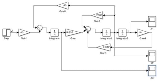
Figure 8.
Block diagram of the linearized EPS.
The control object possesses first-order astatism due to the natural dependence of the displacement on the piston speed. Therefore, from a formal point of view, it is sufficient to use a P controller to obtain an astatic pneumatic cylinder control system with a high static accuracy of working off a step action.
Transient processes of displacement, speed, and pressure in the filling chamber, taking into account proportional control, are shown in Figure 9, Figure 10 and Figure 11. The gain k = 0.00003 is found on the basis of the analysis of the logarithmic amplitude-frequency characteristic (LFC) and the logarithmic phase-frequency characteristic (LFC) of the open-loop system.
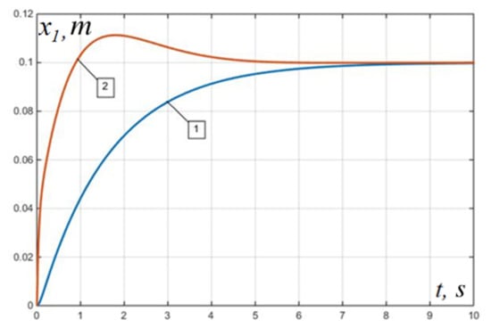
Figure 9.
Transient processes of rod movement for a linear model: (1) with a P controller; (2) with a PID controller.
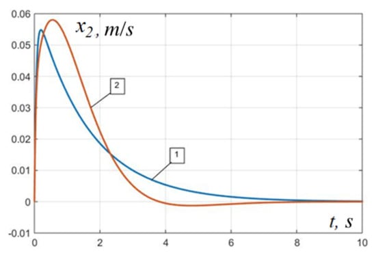
Figure 10.
Transient speed processes for a linear model: (1) with a P controller; (2) with PID controller.
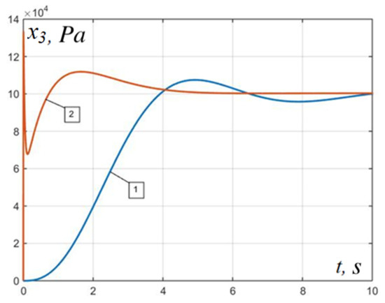
Figure 11.
Inlet pressure transients for the linear model: (1) with a P controller; (2) with a PID controller.
With a more complex form of the input signal, for example, with a power disturbance, a static error appears, which cannot be eliminated only by changing the value of the gain of the P controller. Therefore, to effectively counteract the disturbing influences, the control device must have an integral component of the control law. This can increase the order of astatism and improve the processing of complex input signals and lead to specific problems, such as the appearance of over-regulation and the occurrence of dangerous self-oscillating processes.
The situation can be improved by introducing a differentiating component into the control device, which expands the possibility of choosing the cutoff frequency of an open-loop system, thereby neutralizing the negative influence of the integrating component. This is confirmed by the graphs of transient displacement, speed, and pressure processes using the PID controller, presented in Figure 9, Figure 10 and Figure 11. The parameters of the PID controller were obtained using the LAFC and LPFC of the open-loop system: k = 0.002; Td = 0.0025; Tu = 1.
Comparing the transient processes of the nonlinear controller synthesized using the ADAR method and the linear PID controller, we can conclude that the decay of the transient processes occurs approximately in the same time range, which is 2–5 s. However, when using PID control at the initial moments of time, short-term fluctuations in the amplitude of the drive rod are observed.
It should be noted that the synthesized P and PID controllers are applied to the linearized model shown in Figure 8.
Let us check the performance of the regulators with the selected parameters in relation to the nonlinear plant shown in Figure 12. To do this, add a controller block to the block diagram of the nonlinear mathematical model of the EPS and close the negative feedback along the channel U1 − x1.
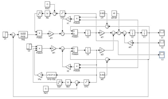
Figure 12.
Nonlinear mathematical model of EPS in the Simulink software.
Note that, in the implemented nonlinear multidimensional model of the EPS, the second input control signal U2f does not participate in the control, the use of which could improve the quality indicators of the system, not to mention other properties of the system. Transient processes of displacement, rod speed, and pressure changes in the filling chamber for a nonlinear EPS with a P controller are shown in Figure 13a, Figure 14a and Figure 15a. Analysis of the graphs shows that the use of a P controller with a selected gain based on the properties of the linearized MM gives satisfactory results; the regulation time is 2 s, while there is a slight overshoot, and the change in filling pressure has unrealistic values.
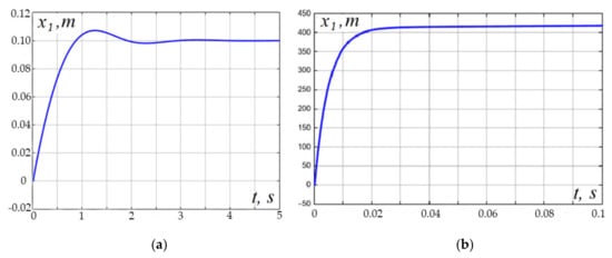
Figure 13.
Transient processes of rod movement for a nonlinear model: (a) with a P controller; (b) PID controller.
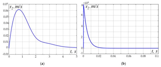
Figure 14.
The transient processes of rod velocity for a nonlinear model: (a) with a P controller; (b) PID controller.
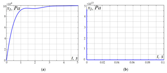
Figure 15.
Transient filling pressure processes for a nonlinear model: (a) with a P controller; (b) PID controller.
Figure 13b, Figure 14b and Figure 15b show the state variable transients for a nonlinear EPS using the linear model PID parameters. At the same time, changes in displacement, speed, and pressure have physically unrealizable, unacceptable values compared to the actual technical characteristics of the type of pneumatic cylinder selected as a simulation.
As a result, we note that finding the optimal parameters of the controller is a rather complicated nonformalized process that requires a creative engineering approach. The results of control of a linear object differ significantly from the results of applying the same control principles, taking into account the nonlinear properties of the model, which will naturally be reflected in the real implementation of control in the technological process. In addition, the linearized MM does not consider the second pressure control channel in the exhaust chamber.
The MM considered in this work is an idealized mathematical description of the functioning of the EPS, considering the conditions for describing thermodynamic processes adopted in [4,6,9]. In this case, it is assumed that the MM describes the system’s behavior with sufficient accuracy, and an assumption is made about the invariability of some parametric characteristics during the operation of the system.
It is quite evident that, in real operating conditions of the EPS, in addition to changing some parameters of the MM EPS, the control system will also be affected by some disturbing external factors, the action of which can significantly reject the desired change in the controlled value.
At the same time, the assumptions made in the formation of the model can lead to a significant discrepancy between the results of mathematical modeling of the synthesized control laws with the values of the controlled parameter change during the real operation of the control system.
3.2. Analysis of Parametric Uncertainties of MM EPS and Application of Typical Control Laws
One of the undefined parameters, the values of which can change during the operation of the control system, is the change in the mass of the load when the control object is moved. Since the mass of an object M is a measure of its inertia, its change in a certain maximum permissible range will directly affect the state variables of the system under study.
Another undefined parameter is the change in gas temperature during its compression and expansion in the cavities of the pneumatic cylinder. So, the compression of air is accompanied by an increase in its temperature, which leads to the expansion of the gas and a decrease in density, while the viscosity of the air increases. In turn, the coefficient of air viscosity determines the value of the friction force and linearly affects the speed of piston movement. The process of gas expansion is accompanied by reverse changes in the properties of air.
Thus, a change in gas temperature directly affects the state variables of the system speed and displacement. This isothermal process is difficult to describe from the point of view of mathematical modeling. To simplify the simulation, it is assumed that, in the system under consideration, the change in the state of the gas occurs according to an adiabatic process, without taking into account heat exchange with the environment. Therefore, in MM EPS, the change in the gas temperature in the filling cavity is not taken into account, but is taken to be equal to the temperature of the main line Tm, while the unknown change in temperature T2 in the exhaust cavity is expressed through the pressure p2 from the equation of coupling of the parameters of the adiabatic process:
Obviously, this assumption will also introduce some corrections in the real change in the controlled values.
Moreover, the force of dry friction Fdry is neglected when simulating, which is a nonlinear discontinuous function of speed sign (V). This is due to the fact that the dry friction force is on the right side of the Cauchy system of equations, which complicates the further analysis of the model, since the DE system must be continuously differentiable concerning all variables included in it.
In turn, the force of viscous friction linearly depends on the speed of movement of the rod (24) through the viscosity coefficient η, the exact value of which can be obtained only by empirical methods. In the absence of experimental data, the averaged piston viscosity coefficient is selected for ideal air parameters in accordance with the type of pneumatic cylinder used, subject to equilibrium quasi-stationary processes.
Based on the foregoing, it can be concluded that the investigated MM of the EPS is parametrically uncertain, and special methods of robust and adaptive control are used to study such models.
It is known that classical control methods based on typical controllers in relation to parametrically uncertain models show unsatisfactory results.
This is illustrated in Figure 16, Figure 17 and Figure 18 by graphs of state variables obtained by varying the model parameters in a nonlinear system (Figure 12) with a P and a PID controller. In this case, the following values of the varied parameters were taken: load mass M = 0.5 kg, coefficient of viscous friction of the rod η = 0.05 (N ∙ s)/m.
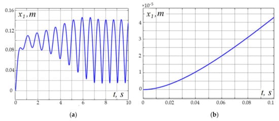
Figure 16.
Transient processes of movement of the model rod with changed parameters: (a) with a P controller; (b) PID controller.
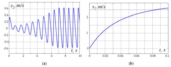
Figure 17.
Transient processes of the stock speed of the model with changed parameters: (a) with a P controller; (b) PID controller.
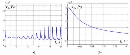
Figure 18.
Transient pressure processes in the model with changed parameters: (a) with a P controller; (b) PID controller.
As can be seen from the graphs in Figure 16, Figure 17 and Figure 18, the methods of classical control theory based on the use of typical linear controllers are unsuitable for controlling a system that has inaccurately defined parametric values in MM.
Analyzing the obtained synergistic and cybernetic control methods, the undeniable advantage of the nonlinear control laws obtained in Section 2.2 and Section 2.3 should be noted, the robustness of which are already incorporated in synergetic control, which consists in the system’s immunity to some permissible changes in its parameters [4,6,9]. This is achieved due to the attractive natural properties of the invariant manifolds introduced into the model.
An analysis of the results shown in Figure 13, Figure 14, Figure 15, Figure 16, Figure 17 and Figure 18 shows that the developed control algorithms based on STC use allow increasing of the speed of positioners. At the same time, smooth braking is ensured when the system reaches the terminal state without overshoot, which can be seen from the simulation of the piston movement to the desired trajectory coordinate presented in Figure 1a and Figure 4a.
The proposed algorithms of the synergetic control theory for the case of throttle control of the pneumatic cylinder piston position, based on the ADAR method, made it possible to solve the problem of the speed of positioners by 20–30%, while providing a positioning error not exceeding 0.1 mm, compared with neural methods and fuzzy algorithms, represented by those found in [3,8,10].
The proposed algorithms for synergistic control of the position of the pneumatic cylinder piston in the case of backpressure control guarantee the smooth braking of the piston in a given co-ordinate of the positioner’s trajectory, in comparison with the results obtained by the authors of [11,41,42], as well as the asymptotic stability of a closed pneumatic control system.
Thus, the obtained laws of synergistic control of the position of the pneumatic cylinder piston can become a theoretical basis for the software and hardware implementation of a new class of pneumatic cylinder control systems that provide speed and accuracy.
4. Conclusions
The article poses a technological problem of controlling the position of the piston of a pneumatic cylinder, which is carried out by synthesizing nonlinear synergetic control laws based on the ADAR method.
A nonlinear synergistic law of throttle control has been developed, in which the compressed air flow is controlled by changing the control action of the PR valve located at the outlet of the exhaust chamber. In addition, a nonlinear synergistic law of backpressure control has been developed, which is carried out by injecting a certain amount of compressed air through the PR into the exhaust chamber.
The proposed procedure for the synergistic synthesis of a controller for throttle control of the position of the pneumatic drive rod allows control laws to be obtained based on a nonlinear mathematical model, which significantly expands the stability area of the synthesized systems compared to traditional ones.
The backpressure control method is implemented due to a co-ordinated change in pressures in the chambers of the pneumatic cylinder, which makes it possible to reduce the flow of incoming compressed air into the filling chamber, due to which some energy efficiency of this control method is achieved compared to the throttle control method, which is confirmed by the above calculations of mass airflow rates. The numerical value of the total airflow in throttle control is 0.0569 m3⁄s and, in backpressure control, is 0.0337 m3⁄s.
Achievement of the set control goals with the help of the nonlinear synergetic control laws obtained in this work is carried out by specifying invariant manifolds, which are attractive surfaces in the phase space of the state, to which the phase trajectories of the system rush. In this case, the stability of the phase motion of the system to invariant manifolds is ensured by introducing functional equations.
A comparative analysis with the most frequently used pneumo-automatics control, the method of standard regulators, is carried out. The resulting linear P and PID controllers were used to control both linear and nonlinear mathematical models of the system. At the same time, the use of a P controller in a linear model gives an oscillatory transient process damped in 2–2.5 s and, when using a PID controller, the process has an overshoot equal to 11.5%. The P and PID control showed satisfactory results in the linearized model of the system, while the control of the obtained standard controllers by the nonlinear model was destructive. This indicates that typical regulators are able to operate effectively only in a limited range of deviations from the stationary regime.
The analysis of the parametric uncertainty of the considered mathematical model is carried out, the main parameters of the model are highlighted, which undergo changes in the course of the real functioning of the system under study.
The inconsistency of the application of classical control laws based on typical controllers to parametrically indefinite mathematical models is shown.
Author Contributions
Conceptualization, E.O. and G.E.V.; methodology, E.O., G.E.V. and P.O.; software, E.O., A.B., S.A.S., E.M.S. and P.O.; validation, E.O. and G.E.V.; formal analysis, E.O., P.O. and G.E.V.; investigation, E.O., G.E.V., A.B., S.A.S. and E.M.S.; resources, P.O; data curation, G.E.V.; writing—original draft preparation, E.O., A.B., S.A.S. and E.M.S.; writing—review and editing, E.O., A.B., S.A.S. and E.M.S.; visualization, E.O., A.B., S.A.S. and E.M.S.; supervision, G.E.V.; project administration, A.B. and G.E.V.; funding acquisition, A.B. All authors have read and agreed to the published version of the manuscript.
Funding
This research received no external funding.
Institutional Review Board Statement
Not applicable.
Informed Consent Statement
Not applicable.
Data Availability Statement
Not applicable.
Acknowledgments
The authors would like to acknowledge the administration of Don State Technical University for their resources and financial support.
Conflicts of Interest
The authors declare no conflict of interest. The funders had no role in the design of the study; in the collection, analyses, or interpretation of data; in the writing of the manuscript, or in the decision to publish the results.
References
- Zhai, A.; Zhang, H.; Wang, J.; Lu, G.; Li, J.; Chen, S. Adaptive neural synchronized impedance control for cooperative manipulators processing under uncertain environments. Robot. Comput.-Integr. Manuf. 2022, 75, 102291. [Google Scholar] [CrossRef]
- Kostoglotov, A.A.; Lazarenko, S.V.; Agapov, A.A. Development of a Structurally Fuzzy Regulator Based on the Condition of the Maximum of the Generalized Power Function Under Constraints on Control. In Proceedings of the Fifth International Scientific Conference “Intelligent Information Technologies for Industry” (IITI’21); Lecture Notes in Networks and Systems; Springer: Cham, Switzerland, 2022; Volume 330, pp. 582–588. [Google Scholar] [CrossRef]
- Nie, Y.; Zhang, M.; Zhang, X. Trajectory Tracking Control of Intelligent Electric Vehicles Based on the Adaptive Spiral Sliding Mode. Appl. Sci. 2021, 11, 11739. [Google Scholar] [CrossRef]
- Obukhova, E. Synergistic method of pneumatic drive control. AIP Conf. Proc. 2019, 2188, 030004. [Google Scholar] [CrossRef]
- Boldareva, K.; Lukyanov, A.; Vernezi, M. Development of a Mechatronic Systems Module Control System Based on MEMS Orientation Sensors. In Proceedings of the 2021 International Conference on Industrial Engineering, Applications and Manufacturing (ICIEAM), Sochi, Russia, 17–21 May 2021; pp. 642–646. [Google Scholar] [CrossRef]
- Obukhova, E. Study of nonlinear synergy control laws on the experimental stand of pneumatic actuators. IOP Conf. Ser. Mater. Sci. Eng. 2021, 1029, 012018. [Google Scholar] [CrossRef]
- Benavoli, A.; Balleri, A.; Farina, A. Joint Waveform and Guidance Control Optimization by Statistical Linearisation for Target Rendezvous. In Proceedings of the 2021 IEEE Radar Conference (RadarConf21), Atlanta, GA, USA, 7–14 May 2021; pp. 1–6. [Google Scholar] [CrossRef]
- Riaz, M.; Rehan, M.; Ashraf, M. Synchronization of nonlinear master-slave systems under input delay and slope-restricted input nonlinearity. Complexity 2016, 21, 220–233. [Google Scholar] [CrossRef]
- Obukhova, E.; Veselov, G. Synergetic Synthesis of Adaptive Control of an Electro-pneumatic System. In Proceedings of the 2020 7th International Conference on Control, Decision and Information Technologies (CoDIT), Prague, Czech Republic, 29 June–2 July 2020; pp. 13–18. [Google Scholar]
- Ng, J.; Asada, H.H. Model Predictive Control and Transfer Learning of Hybrid Systems Using Lifting Linearization Applied to Cable Suspension Systems. IEEE Robot. Autom. Lett. 2022, 7, 682–689. [Google Scholar] [CrossRef]
- Veselov, G.; Tselykh, A.; Sharma, A. Introduction to the Special Issue: Futuristic trends and the emergence of technology in biomedical, nonlinear dynamics and control engineering. J. Vibroeng. 2021, 23, 1315–1317. [Google Scholar] [CrossRef]
- Prvulovic, C.; Mosorinski, P.; Radosav, D.; Tolmac, J.; Josimovic, M.; Sinik, V. Determination of the temperature in the cutting zone while processing machine plastic using fuzzy-logic controller (FLC). Ain Shams Eng. J. 2022, 13, 101624. [Google Scholar] [CrossRef]
- Silva, F.L.; Silva, L.C.A.; Eckert, J.J.; Yamashita, R.Y.; Lourenço, M.A.M. Parameter influence analysis in an optimized fuzzy stability control for a four-wheel independent-drive electric vehicle. Control. Eng. Pract. 2022, 120, 105000. [Google Scholar] [CrossRef]
- Salem, A.A.; ElDesouky, A.A.; Alaboudy, A.H.K. New analytical assessment for fast and complete pre-fault restoration of grid-connected FSWTs with fuzzy-logic pitch-angle controller. Int. J. Electr. Power Energy Syst. 2022, 136, 107745. [Google Scholar] [CrossRef]
- Angundjaja, C.Y.; Wang, Y.; Jiang, W. Power Management for Connected EVs Using a Fuzzy Logic Controller and Artificial Neural Network. Appl. Sci. 2022, 12, 52. [Google Scholar] [CrossRef]
- Mondal, S.; Ray, R.; Reddy, S.; Nandy, S. Intelligent controller for nonholonomic wheeled mobile robot: A fuzzy path following combination. Math. Comput. Simul. 2022, 193, 533–555. [Google Scholar] [CrossRef]
- Yang, T.; Sun, N.; Fang, Y. Adaptive Fuzzy Control for Uncertain Mechatronic Systems With State Estimation and Input Nonlinearities. IEEE Trans. Ind. Inform. 2022, 18, 1770–1780. [Google Scholar] [CrossRef]
- Luo, G.; Li, H.; Ma, B.; Wang, Y. Design and experimental research of observer-based adaptive type-2 fuzzy steering control for automated vehicles with prescribed performance. Mechatronics 2022, 81, 102700. [Google Scholar] [CrossRef]
- Zhang, Z.; Feng, T.; Zheng, Z.; Wu, H.; Tan, Y. Fuzzy Active Disturbance Rejection Control for Hypersonic Vehicle. In Advances in Guidance, Navigation and Control; Lecture Notes in Electrical Engineering; Springer: Singapore, 2022; Volume 644, pp. 2501–2513. [Google Scholar] [CrossRef]
- Zhang, Q.; Wei, Y.; Li, X. Quadrotor Attitude Control by Fractional-Order Fuzzy Particle Swarm Optimization-Based Active Disturbance Rejection Control. Appl. Sci. 2021, 11, 11583. [Google Scholar] [CrossRef]
- Razzaghian, A. A fuzzy neural network-based fractional-order Lyapunov-based robust control strategy for exoskeleton robots: Application in upper-limb rehabilitation. Math. Comput. Simul. 2022, 193, 567–583. [Google Scholar] [CrossRef]
- Yang, Y.; Li, Y.; Liu, X.; Huang, D. Adaptive neural network control for a hydraulic knee exoskeleton with valve deadband and output constraint based on nonlinear disturbance observer. Neurocomputing 2022, 473, 14–23. [Google Scholar] [CrossRef]
- Shetty, N.; Kumar, P. Comparative Study on Flyback Converter with PID Controller and Neural Network Controller. In Advances in Renewable Energy and Electric Vehicles; Lecture Notes in Electrical Engineering; Springer: Singapore, 2022; Volume 767, pp. 77–87. [Google Scholar] [CrossRef]
- Liu, Z.-G.; Tian, Y.-P.; Sun, Z.-Y. An adaptive homogeneous domination method to time-varying control of nonlinear systems. Int. J. Robust Nonlinear Control 2022, 32, 527–540. [Google Scholar] [CrossRef]
- Khinikadze, T.; Rybak, A.; Vyborova, N.; Zubtsov, V. Adaptive Hydromechanical Drilling Rig Drive. In XIV International Scientific Conference “INTERAGROMASH 2021”, Proceedings of the INTERAGROMASH 2021, Rostov-on-Don, Russia, 24–26 February 2021; Lecture Notes in Networks and Systems; Springer: Cham, Switzerland, 2022; Volume 246, pp. 192–197. [Google Scholar] [CrossRef]
- Rybak, A.; Gorbunov, R.; Olshevskaya, A.; Ugrekhelidze, N.; Egyan, M. Mathematical Model of a Throttle Flow Divider with an Elastic Regulating Element. In XIV International Scientific Conference “INTERAGROMASH 2021”, Proceedings of the INTERAGROMASH 2021, Rostov-on-Don, Russia, 24–26 February 2021; Lecture Notes in Networks and Systems; Springer: Cham, Switzerland, 2022; Volume 246, pp. 207–216. [Google Scholar] [CrossRef]
- Huang, Z.; Xu, Y.; Ren, W.; Fu, C.; Cao, R.; Kong, X.; Li, W. Design of Position Control Method for Pump-Controlled Hydraulic Presses via Adaptive Integral Robust Control. Processes 2022, 10, 14. [Google Scholar] [CrossRef]
- Chen, Q.; Chen, H.; Zhu, D.; Li, L. Design and Analysis of an Active Disturbance Rejection Robust Adaptive Control System for Electromechanical Actuator. Actuators 2021, 10, 307. [Google Scholar] [CrossRef]
- Beskopylny, A.; Lyapin, A.; Anysz, H.; Meskhi, B.; Veremeenko, A.; Mozgovoy, A. Artificial Neural Networks in Classification of Steel Grades Based on Non-Destructive Tests. Materials 2020, 13, 2445. [Google Scholar] [CrossRef] [PubMed]
- Beskopylny, A.; Meskhi, B.; Beskopylny, N.; Chukarina, I.; Isaev, A.; Veremeenko, A. Strengthening of Welded Joints of Load-Bearing Structures of Robotic Systems with Ball-Rod Hardening. In Robotics, Machinery and Engineering Technology for Precision Agriculture; Smart Innovation, Systems and Technologies; Springer: Singapore, 2022; Volume 247, pp. 1–11. [Google Scholar] [CrossRef]
- Beskopylny, A.; Meskhi, B.; Beskopylny, N.; Bezuglova, M. Quality Control of Frame Structures of Robotic Systems by Express Nondestructive Methods. Robotics, Machinery and Engineering Technology for Precision Agriculture; Smart Innovation, Systems and Technologies; Springer: Singapore, 2022; Volume 247, pp. 13–20. [Google Scholar] [CrossRef]
- Ren, H.-P.; Jiao, S.-S.; Li, J.; Deng, Y. Adaptive neural network control of pneumatic servo system considering state constraints. Mech. Syst. Signal Processing 2022, 162, 107979. [Google Scholar] [CrossRef]
- Liu, W.; Mehdipour, N.; Belta, C. Recurrent Neural Network Controllers for Signal Temporal Logic Specifications Subject to Safety Constraints. IEEE Control Syst. Lett. 2022, 6, 91–96. [Google Scholar] [CrossRef]
- Hua, L.; Zhang, J.; Li, D.; Xi, X. Fault-Tolerant Active Disturbance Rejection Control of Plant Protection of Unmanned Aerial Vehicles Based on a Spatio-Temporal RBF Neural Network. Appl. Sci. 2021, 11, 4084. [Google Scholar] [CrossRef]
- Muñoz, F.; Cervantes-Rojas, J.S.; Valdovinos, J.M.; Sandre-Hernández, O.; Salazar, S.; Romero, H. Dynamic Neural Network-Based Adaptive Tracking Control for an Autonomous Underwater Vehicle Subject to Modeling and Parametric Uncertainties. Appl. Sci. 2021, 11, 2797. [Google Scholar] [CrossRef]
- Zhang, Z.; Chu, L.; Zhang, J.; Guo, C.; Li, J. Design of Vehicle Stability Controller Based on Fuzzy Radial Basis Neural Network Sliding Mode Theory with Sideslip Angle Estimation. Appl. Sci. 2021, 11, 1231. [Google Scholar] [CrossRef]
- Xu, D.; Wang, Q.; Li, Y. Adaptive Optimal Robust Control for Uncertain Nonlinear Systems Using Neural Network Approximation in Policy Iteration. Appl. Sci. 2021, 11, 2312. [Google Scholar] [CrossRef]
- Zare, A.; Mirrezapour, S.Z.; Hallaji, M.; Shoeibi, A.; Jafari, M.; Ghassemi, N.; Alizadehsani, R.; Mosavi, A. Robust Adaptive Synchronization of a Class of Uncertain Chaotic Systems with Unknown Time-Delay. Appl. Sci. 2020, 10, 8875. [Google Scholar] [CrossRef]
- Kolesnikov, A.A. Synergetics and Problems of Control Theory; FIZMATLIB: Moscow, Russia, 2004; 504p, ISBN 5-9221-0336-9. Available online: https://www.studentlibrary.ru/book/ISBN5922103369.html (accessed on 8 January 2022).
- Popov, D.N. Mechanics of Hydraulic and Pneumatic Drives; Bauman University: Moscow, Russia, 2001; Volume 7, 320p, ISBN 5-7038-1777-3. Available online: https://www.labirint.ru/books/539113/ (accessed on 8 January 2022).
- Zakovorotny, V.; Gvindjiliya, V.E. Synergies in control of the cutting processes. MATEC Web Conf. 2018, 226, 02009. [Google Scholar] [CrossRef][Green Version]
- Zakovorotny, V.; Gvindjiliya, V.E. Correlation of the dynamic properties of the manufacturing process on metal-cutting machines and energy efficiency of the process. IOP Conf. Ser. Mater. Sci. Eng. 2020, 900, 012007. [Google Scholar] [CrossRef]


Publisher’s Note: MDPI stays neutral with regard to jurisdictional claims in published maps and institutional affiliations. |
© 2022 by the authors. Licensee MDPI, Basel, Switzerland. This article is an open access article distributed under the terms and conditions of the Creative Commons Attribution (CC BY) license (https://creativecommons.org/licenses/by/4.0/).