Article

Human Activity Signatures Captured under Different Directions Using SISO and MIMO Radar Systems

Faculty of Engineering and Science, University of Agder, 4898 Grimstad, Norway
*
Author to whom correspondence should be addressed.
Appl. Sci. 2022, 12(4), 1825; https://doi.org/10.3390/app12041825
Submission received: 4 January 2022 / Revised: 28 January 2022 / Accepted: 1 February 2022 / Published: 10 February 2022
(This article belongs to the Special Issue Sensor-Based Human Activity Recognition in Real-World Scenarios)

Abstract

:
In this paper, we highlight and resolve the shortcomings of single-input single-output (SISO) millimeter wave (mm-Wave) radar systems for human activity recognition (HAR). A 2 × 2 distributed multiple-input multiple-output (MIMO) radar framework is presented to capture human activity signatures under realistic conditions in indoor environments. We propose to distribute the two pairs of collocated transmitter–receiver antennas in order to illuminate the indoor environment from different perspectives. For the proposed MIMO system, we measure the time-variant (TV) radial velocity distribution and TV mean radial velocity to observe the signatures of human activities. We deploy the Ancortek SDR-KIT 2400T2R4 mm-Wave radar in a SISO as well as a 2 × 2 distributed MIMO configuration. We corroborate the limitations of SISO configurations by recording real human activities in different directions. It is shown that, unlike the SISO radar configuration, the proposed MIMO configuration has the ability to obtain superior human activity signatures for all directions. To signify the importance of the proposed 2 × 2 MIMO radar system, we compared the performance of a SISO radar-based passive step counter with a distributed MIMO radar-based passive step counter. As the proposed 2 × 2 MIMO radar system is able to detect human activity in all directions, it fills a research gap of radio frequency (RF)-based HAR systems.

1. Introduction

1.1. General Background

In recent years, the number of application areas of human activity recognition (HAR) has greatly increased, such as remote health assessment [1], smart home [2], smart surveillance [3], human–computer interaction [4], sports [5], autopilots [6], and social robotics [7]. RF-based in-home sensing is still considered a developing technology facing some key challenges regarding HAR. However, the attractive features of RF-based HAR systems have brought them to the forefront of indoor HAR systems. Alternatively, vision-based and wearable sensor-based HAR systems have already produced numerous and adequate results. However, unlike RF sensors, visual sensors such as cameras or light detection and ranging (LiDAR) may suffer from issues such as privacy invasion, sensitivity to lighting, and obstructive illumination. On the other hand, wearable sensors such as accelerometers, magnetometers, gyroscopes, and emergency push buttons are radically intrusive, fragile, must be carried by the user, and are prone to user negligence.
RF sensors such as Wi-Fi and radar systems must have robustness to environmental variations, lighting conditions, user’s privacy, and nonobstructive illumination. Over the years, two established technologies, Wi-Fi and radar, have been explored in RF sensing for HAR [8,9,10,11]. Unfortunately, commercial Wi-Fi devices suffer from carrier frequency offsets due to hardware limitations and environmental variations [12]. As a consequence of carrier frequency offsets, the phases of the channel frequency response are particularly noisy in commercial Wi-Fi devices and thus hard to utilize [8,10,11,13]. In contrast, with the application of radar signal processing [11,14,15,16], data fusion techniques [17,18], machine learning, and deep learning algorithms, it will be possible in the coming years to track and classify multiple human activities by means of radar systems in unprecedented complex settings. The work presented in this paper is a step forward in that direction, where we have addressed the problem of the direction-independent recognition of human activities and proposed an effective solution in the context of RF sensing. It should be mentioned that radars have traditionally been deployed by official or governmental entities in application areas such as weather [19], naval [20] and aerial surveillance [21], air defense [22], ground traffic control [23], altimeters [24], geology [25], and astronomical research [26]. However, due to their miniaturization and cost effectiveness, the current radar systems have found utilization in self-driving cars [27,28,29], emerging medical solutions [30], and HAR systems [31,32,33,34].

1.2. Related Work

One crucial challenge for radar-based HAR systems is the direction of motion of certain activity in relation to the illuminating radar. For instance, a person may fall in a direction either parallel or perpendicular to the radar’s boresight. Conceivably, a monostatic single-input single-output (SISO) radar will not be able to detect the fall if the fall direction is perpendicular to the boresight of the radar. This is due to the fact that the radar systems are merely sensitive to the changes in the scatterer’s radial distance with respect to the radar itself. A scatterer moving perpendicular to the radar’s boresight has zero Doppler frequency and thus appears as a stationary object to the radar and can therefore not be distinguished from other stationary objects in an indoor environment by the radar system. Generally, a strong degradation of the classification performance is expected for activities with a greater angle of motion to the radar’s boresight. The prior state-of-the-art approaches to alleviate this problem are delineated here along with their limitations.
The authors in [35,36] suggest that a SISO radar positioned on the ceiling can detect fall activities. However, this is not a general solution for direction-independent HAR. For direction-independent HAR, it is understandably compelling to use monostatic beamforming multiple-input multiple-output (MIMO) radars that are capable of measuring the angular information [37]. However, these systems are often limited by their angular resolution, which in turn limits their cross-range resolution significantly. Such monostatic MIMO radars do not perform adequately, especially not for persons relatively far away from the radar, which degrades the overall classification accuracy. The authors in [38] use the phase information of frequency modulated continuous wave (FMCW) monopulse radars to measure the angle of arrival, but the study is limited to hand gesture sensing. The authors in [39] combine the FMCW mode of radars with interferometry to track vital signs and detect position and life activities, but they do not generally address the challenges caused by the direction of human activities. To improve the angular resolution, direction of arrival algorithms such as the “estimation of signal parameters via rotational invariance techniques” (ESPRIT) method and “multiple signal classification” (MUSIC) method can also be used [40], but these direction of arrival algorithms usually require a high signal to noise ratio [41]. Although the authors of [18] discuss a multistatic Doppler radar, the study is limited to the detection of armed persons. A bi-static radar configuration is used in [42] to improve the activity classification performance. However, the quality of data can be improved by using a MIMO radar system instead. The performance of another radar configuration is explored in [43] using a MIMO radar system in bi-static configuration, but the study is limited to personnel localization only.

1.3. Contributions

The problems faced by the aforementioned SISO and MIMO radar systems motivate us to develop a solution for a direction-independent HAR system. To illuminate the indoor environment from different perspectives, we propose to distribute multiple pairs of collocated transmitter–receiver radar antennas in an indoor environment for a direction-independent human activity detection system (see Section 4). This multi-perspective view of a distributed MIMO radar system will allow us to render direction-independence for HAR. The micro-Doppler signatures or radial velocity distribution (see Section 2) obtained using the proposed approach can help us to design HAR systems capable of classifying complex activities. Thus, the proposed framework is a step forward towards a more pragmatic and sophisticated radar-based HAR system.
The principal contributions of this work are listed as follows:
  • A basic multi-perspective 2 × 2 MIMO radar system is presented which can be easily scaled to a higher number of transmitter and receiver antennas for better performance.
  • We analyze the TV radial velocity distribution and TV mean radial velocity for the proposed distributed antenna configuration.
  • For the 2 × 2 MIMO radar configuration, we investigate the impact of a human falling incident and a walking activity on the measured radial velocity distribution and measured mean radial velocity.
  • We analyze the impact of two different activities performed in three different directions on the measured channel characteristics for a SISO and a 2 × 2 MIMO radar system. We corroborate the limitations of the SISO radar system by analyzing the real radar data.
  • We demonstrate the robustness of the proposed 2 × 2 MIMO radar system against different directions of the actual human walking and falling activity. We show that the proposed solution is able to detect the human gross motor activity in the horizontal xy-plane.
  • We analyze the performance of a radar-based passive step counter by integrating it with a SISO radar system. It is shown that the radar-based passive step counter, when used with a SISO radar system, may miss some human walking steps or detect false steps depending on the walking direction.
  • It is shown that by deploying the radar-based passive step counter with the proposed 2 × 2 MIMO radar framework, the step counter would accurately detect the number of steps for all considered human walking directions.
  • Finally, we quantify, compare, and numerically assess the performance of the SISO and 2 × 2 MIMO radar systems by using the dynamic time warping (DTW) [44] distance metric.

1.4. Paper Organization

The paper is organized as follows. The system model and preprocessing techniques are delineated in Section 2. Section 3 describes the problems encountered with SISO radar systems for detecting human activities performed in different directions. Section 4 shows how the proposed 2 × 2 MIMO radar system overcomes the shortcomings of the SISO radar system. The experimental results for actual human activities are detailed in Section 3 and Section 4 for the SISO and 2 × 2 MIMO radar systems, respectively. Finally, Section 6 draws the conclusions.

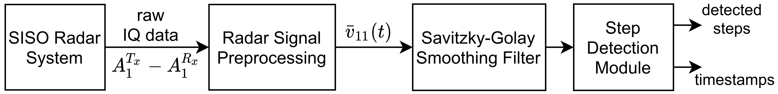
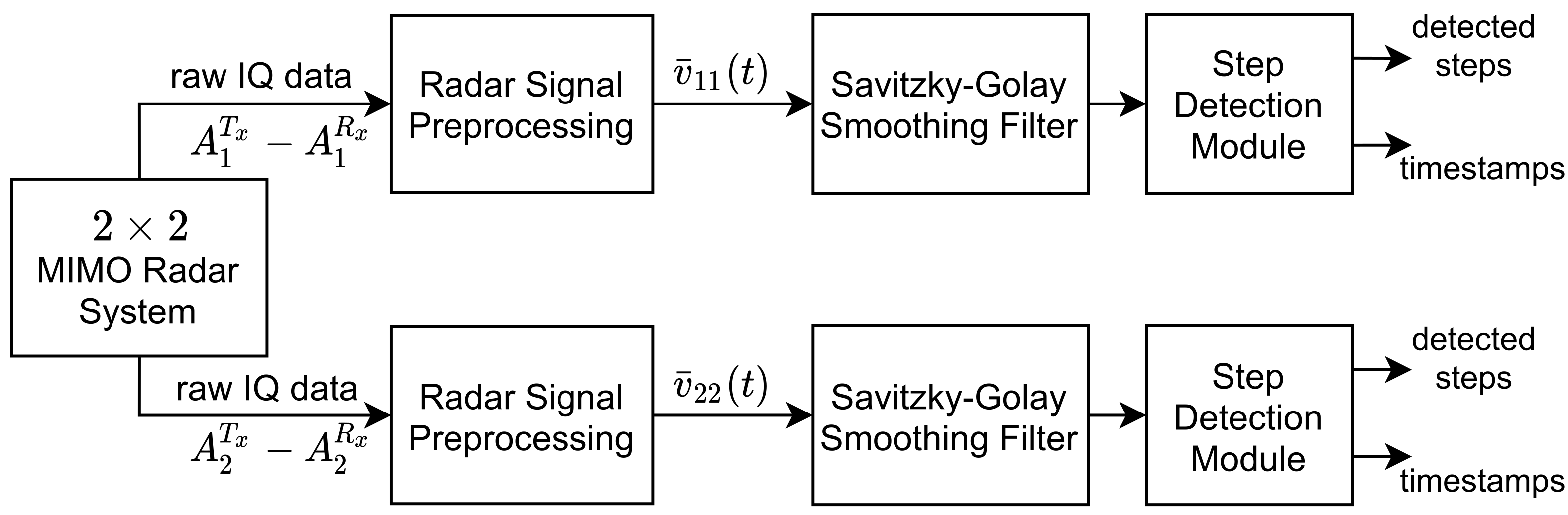
2. Radar Signal Preprocessing

In this paper, we have adopted an FMCW 2 × 2 MIMO radar to capture the micro-Doppler signatures of a moving person from different perspectives. The fundamental waveform transmitted by the ith transmitter antenna A i T x ( i = 1 , 2 ) of the FMCW radar is the chirp waveform [45]
c i ( t ) = exp j 2 π f 0 t + γ 2 t 2 + j ϕ i , 0 t < T s w
where t denotes the fast time, f 0 is the initial RF frequency, γ is the slope of the linear chirp in the time-frequency domain, ϕ i is the initial phase, and T s w is the chirp interval. The two transmitters of the 2 × 2 MIMO radar operate in a time division multiple access (TDMA) mode. For n = 0 , 1 , , the time windows occupied by the ith transmitter are ( 2 n + i 1 ) T s w t < ( 2 n + i ) T s w . The chirp waveform is transmitted periodically by each transmitter in their respective time slot. The overall transmit signal s i ( t , t ) can be represented as a sum of shifted versions of the fundamental waveform c i ( t ) according to
s i ( t , t ) = n = 0 c i ( t ) δ ( t t n , i )
for i = 1 , 2 , where δ ( · ) is a Dirac delta function, t is the slow time, and t n , i is the discrete slow time. For TDMA mode, the discrete slow time t n , i is related to chirp interval  T s w by t n , i = ( 2 n + i 1 ) T s w . The expression (2) allows us to represent the transmit signal  s i ( t , t ) as function of two separate time variables.
The wireless channel link between the ith transmitter antenna A i T x and jth receiver antenna A j R x is denoted by A i T x A j R x , where i , j { 1 , 2 } . When modeling the human body as a cluster of L scatterers [46], the beat signal s b , i j ( l ) ( t , t ) corresponding to the lth scatterer and the channel link A i T x A j R x can be represented by
s b , i j ( l ) ( t , t ) = n = 0 a i j ( l ) exp j 2 π f b , i j ( l ) t + ϕ i j ( l ) δ ( t t n , i )
for l = 1 , 2 , , L . The symbol a i j ( l ) stands for the path gain, which is primarily determined by the path loss and the radar cross section. For simplicity, we assume that the path gain  a i j ( l ) is constant within the observation interval. For the lth scatterer, the beat frequency  f b , i j ( l ) and phase  ϕ i j ( l ) in (3) are given as [47]
f b , i j ( l ) = 2 d i j ( l ) γ c 0
and
ϕ i j ( l ) = 4 π d i j ( l ) λ
respectively, where d i j ( l ) is the total propagation distance, which is given by
d i j ( l ) = 1 2 d l , i T x + d l , j R x + L i T x + L j R x .
The symbol c 0 represents the speed of light in vacuum and λ is the wavelength. The quantity d l , i T x in (6) is the distance between the transmitter antenna A i T x and the lth scatterer. Similarly, the distance between the receiver antenna A j R x and the lth scatterer is represented by d l , j R x . The lengths of the RF cables are denoted as L i T x and L j R x in (6) for the transmitter antenna A i T x and receiver antenna A j R x , respectively. In this paper, the transmitter antenna  A i T x and receiver antenna A j R x are collocated for i = j . As a consequence, the distances from the transmitter antenna  A i T x and receiver antenna  A j R x to the lth scatterer become identical for i = j ; i.e., d l , i T x = d l , j R x ( i = 1 , 2 ). Moreover, the RF cable lengths of the transmitter antenna A i T x and receiver antenna A j R x are the same for i = j , i.e., L i T x = L i R x ( i = 1 , 2 ). For the lth scatterer and the aforementioned antenna placement constraints, the total propagation distance d i j ( l ) in (6) reduces to the sum of the radar radial range r i j ( l ) and the RF cable length  L i ; i.e.,
d i j ( l ) = r i j ( l ) + L i
where the radar radial range r i j ( l ) is the Euclidean distance between the lth scatterer and the transmitter antenna A i T x or the receiver antenna A j R x , and L i = L i T x = L j R x for i = j . Note that we distribute multiple pairs of collocated transmitter–receiver antennas; therefore, the transmitter antenna  A i T x and receiver antenna  A j R x are not collocated for i j . Consequently, to compute the total propagation distance d i j ( l ) , the expression in (6) must be used instead of (7) for i j . With reference to [48], the composite beat signal s b , i j ( t , t ) is the sum of all beat signals s b , i j ( l ) ( t , t ) associated with the cluster of L scatterers, which can be expressed as
s b , i j ( t , t ) = l = 1 L s b , i j ( l ) ( t , t ) .
In an FMCW radar, the composite beat signal s b , i j ( t , t ) is produced by the quadrature mixer component of the radar. The analog to digital converter (ADC) digitizes the composite beat signal s b , i j ( t , t ) with a sampling rate of  F s with respect to fast time  t . For each chirp interval T s w , the digitized data are stacked in a raw data matrix  D i j . The rows and columns of the raw data matrix D i j contain samples of the composite beat signal s b , i j ( t , t ) in the fast-time and slow-time domain, respectively. The slow-time sampling interval is actually equal to the chirp interval  T s w .
The fast Fourier transform (FFT) performed on the raw data matrix D i j with respect to fast time t and slow time t is known as the range FFT and Doppler FFT, respectively. For the channel link A i T x A j R x , the expression for the range FFT, also known as the beat frequency profile  S b , i j ( f b , t ) , is given as
S b , i j ( f b , t ) = 0 T s w s b , i j ( t , t ) e j 2 π f b t d t
where f b represents the beat frequency. The STFT is related to the slow-time domain t and applies on the function resulting from the range FFT in (9). In other words, the data from the beat frequency profile  S b , i j ( f b , t ) are multiplied by a rectangular window function W r ( · ) sliding in slow time t to provide overlapping segments for the FFT operation; i.e.,
X i j ( f b , f , t ) = S b , i j ( f b , t ) W r ( t t ) e j 2 π f t d t
where f is the Doppler frequency and t denotes the running time.
Finally, the TV micro-Doppler signature  S i j ( f , t ) is obtained by integrating X i j ( f b , f , t ) over the beat frequencies  f b from zero to the maximum beat frequency  f b , max and computing the absolute value to the power of 2; i.e., [49]
S i j ( f , t ) = | 0 f b , max X i j ( f b , f , t ) d f b | 2 .
Note that, according to the Nyquist sampling theorem, the maximum beat frequency f b , max is equal to 1 / 2 of the ADC sampling rate F s ; i.e., f b , max = F s / 2 .
The TV mean Doppler shift B i j ( 1 ) ( t ) can be obtained from the micro-Doppler signature  S i j ( f , t ) according to the relation [50]
B i j ( 1 ) ( t ) = f S i j ( f , t ) d f S i j ( f , t ) d f .
As the Doppler frequency f can be mapped on the radial velocity v according to v = c 0 f / ( 2 f 0 ) , we can obtain the TV radial velocity profile  V i j ( v , t ) from the TV micro-Doppler signature  S i j ( f , t ) as
V i j ( v , t ) = S i j 2 f 0 c 0 v , t .
The TV micro-Doppler signature  S i j ( f , t ) in (11) is computed from the composite beat signal s b , i j ( t , t ) , and thus it contains the micro-Doppler information of all L scatterers with their respective strengths. Analogously, the radial velocity profile  V i j ( v , t ) in (13) contains the radial velocity information of each scatterer with respect to the slow time t. The strength or power of the lth scatterer in the radial velocity profile  V i j ( v , t ) depends on the path gain  a i j ( l ) .
From the TV radial velocity profile  V i j ( v , t ) , we can compute the TV radial velocity distribution  p i j ( v , t ) by
p i j ( v , t ) = V i j ( v , t ) V i j ( v , t ) d v
from which we can obtain the mean radial velocity  v ¯ i j ( t ) using the relation
v ¯ i j ( t ) = v p i j ( v , t ) d v .
As good descriptive statistics that quantitatively summarize all the main features of the TV micro-Doppler signature  S i j ( f , t ) or radial velocity distribution  p i j ( v , t ) , we can utilize the mean Doppler shift  B i j ( 1 ) ( t ) or the mean radial velocity  v ¯ i j ( t ) , respectively. The TV mean Doppler shift  B i j ( 1 ) ( t ) in (12) is basically a weighted arithmetic mean of the TV micro-Doppler signature  S i j ( f , t ) . Similarly, the mean radial velocity  v ¯ i j ( t ) in (15) is the weighted average of the velocity components of all L human body segments computed for each time instance t. The TV radial velocity distribution  p i j ( v , t ) and TV mean radial velocity  v ¯ i j ( t ) will play an important role in analyzing real-world measurement data in Section 3 and Section 4.

3. Human Activity Signatures Measured by Using a SISO FMCW Radar System

An FMCW radar modulates its transmit signal frequency to detect the radial range of a target. The electromagnetic signal transmitted by the FMCW radar interacts with stationary and non-stationary objects present in the radar’s range, thus altering the amplitude, phase, and frequency of the transmitted signal. After applying suitable radar signal preprocessing techniques, the phase and frequency variations of the backscattered signal provide the range and micro-Doppler information of the target (see Section 2). As part of the preprocessing, the multipath components originating from objects relatively stationary to the radar system are filtered out, thereby making the radar system merely sensitive to the radial component of the object’s motion. Therefore, detecting and processing a scatterer’s motion perpendicular to the radar’s boresight becomes a major challenge. For a human body under observation, the radar signals are reflected off the human body segments. Generally, human body segments can be modeled as a cluster of point scatterers [46]. The TV radial range and micro-Doppler signature caused by such moving body segments can be measured from the backscattered radar signals.
In this section, we primarily focus on the impact of the direction of human activity on the TV radial velocity distribution  p i j ( v , t ) of a SISO radar system, where i , j = 1 . To highlight the limitations of the SISO radar system deployed in an indoor environment, we first describe the measurement setup. Secondly, we illustrate three different experimental scenarios in which the human activities are performed and analyzed. Thirdly, we show the radial velocity distribution  p 11 ( v , t ) and mean radial velocity  v ¯ 11 ( t ) derived from measurements of a SISO radar system. Finally, the implications of different directions of human activities on the performance of an RF-based step counting algorithm are discussed for the considered SISO radar system.

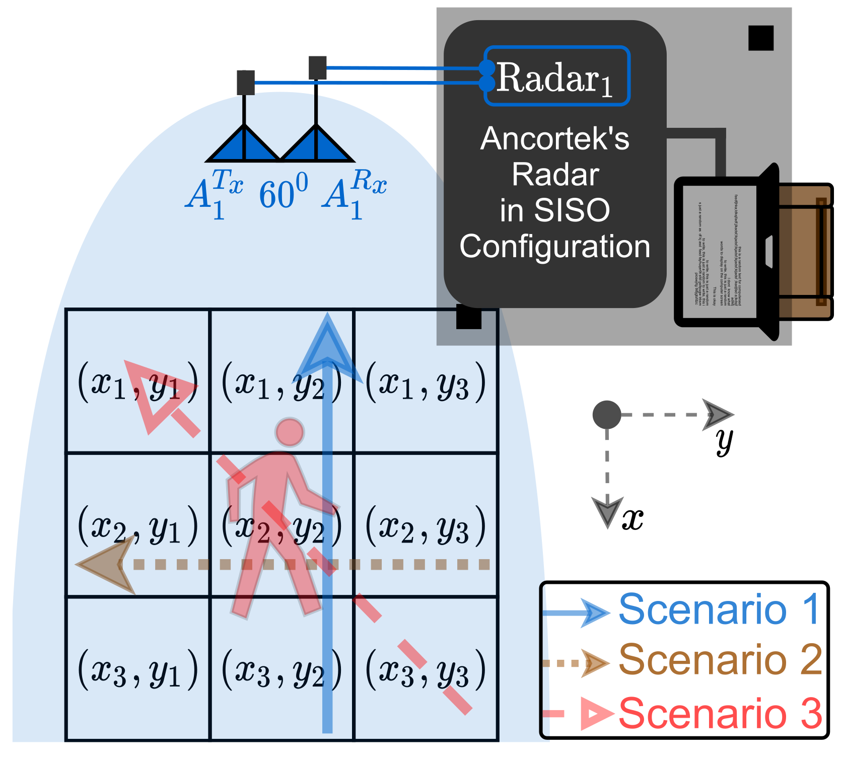
3.1. Measurement Setup

In this paper, we used a commercially available MIMO radar system called Ancortek SDR-KIT 2400T2R4, which is an FMCW millimeter wave (mm-Wave) radar operating at 24 GHz. We configured the radar in SISO mode of operation and used a single transmitter antenna A 1 T x and a single receiver antenna A 1 R x . We used a monostatic configuration of the antennas to capture the micro-Doppler information of a human body moving in the xy-plane. In a monostatic configuration, the transmitter and receiver antennas of the SISO radar system are collocated. The SISO FMCW radar system was configured according to the parameters listed in Table 1. The pulse repetition frequency (PRF) of the SISO FMCW radar system is equal to the inverse of the chirp interval T s w , i.e., PRF = 1 / T s w . This is due to the fact that we do not require the TDMA mode of operation for the SISO radar system. In other words, the transmitter antenna A 1 T x transmits the chirp waveform c i ( t ) in (1) continuously in time.

3.2. Scenarios of Human Activities

The indoor environment is a laboratory cluttered with fixed items such as wooden furniture, computers, routers, and other miscellaneous laboratory tools and electronics. The direction of activities of a person relative to the SISO radar system are depicted in Figure 1. To elucidate the direction of human motion in an experiment, we refer throughout this section to a 3 × 3 grid illustrated in Figure 1, in which three different scenarios of human movement are represented by different markings. The human activities have been carried out in three different directions in order to demonstrate the limitations of the SISO radar system in the context of HAR. Scenario 1 is a trivial scenario, where a person moves towards the SISO radar system. In this case, the human motion is parallel to the radar boresight, implying that the SISO radar system does not encounter any problem capturing the micro-Doppler signatures with high accuracy. Most of the research on HAR is limited to merely Scenario 1 with the SISO radar systems in a monostatic configuration. However, the shortcomings of SISO radar configuration come to the surface if we consider a human activity that is perpendicular to the boresight of the SISO radar system. Thus, in Scenario 2, when a person moves perpendicular to the radar boresight or moves from the position ( x 2 , y 3 ) to ( x 2 , y 1 ) , then the SISO radar system captures a completely different micro-Doppler signature that is suboptimal for HAR. In Scenario 3, the person moves diagonally in the 3 × 3 grid of Figure 1, either from ( x 3 , y 3 ) to ( x 1 , y 1 ) or from ( x 1 , y 1 ) to ( x 3 , y 3 ) . We expect to acquire adequate human activity signatures in Scenario 3, but not as good as the human activity signatures of Scenario 1. For each of Scenarios 1, 2, and 3, we consider a walking and falling activity. The results of the recognized human activities by employing the monostatic SISO radar system are shown in the next subsection for Scenarios 1, 2, and 3.

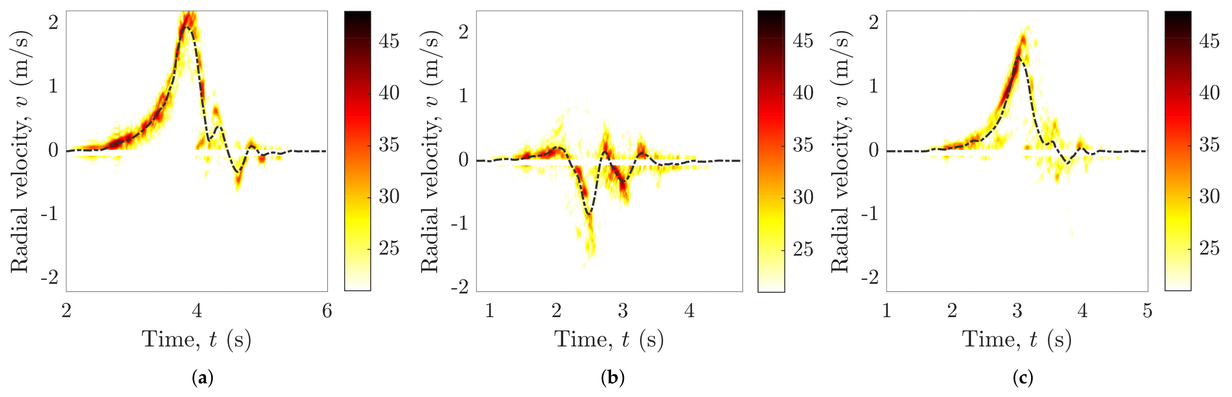
3.3. Results for the Monostatic SISO Configuration

To show the limitations of the aforementioned monostatic SISO radar system, we recorded the human motion in three different directions, which are depicted in Figure 1. We process the recorded raw radar data by means of radar signal preprocessing, as described in Section 2. The radial velocity distribution  p 11 ( v , t ) has been computed by using (14), and the mean radial velocity  v ¯ 11 ( t ) has been obtained from (15) for the human walking and falling activities. Figure 2 and Figure 3 show the measured radial velocity distribution  p 11 ( v , t ) over time t corresponding to a falling and walking activity, respectively. The black dashed lines in Figure 2 and Figure 3 represent the measured mean radial velocity  v ¯ 11 ( t ) . We can see from Figure 2 and Figure 3 that the measured mean radial velocity  v ¯ 11 ( t ) provides a descriptive statistic, which quantitatively summarizes all the main features of the TV radial velocity distribution  p 11 ( v , t ) .
Recall from Figure 1 that in Scenario 1, a person moves parallel to the SISO radar boresight—i.e., from position ( x 3 , y 2 ) to ( x 1 , y 2 ) —whereas in Scenario 2, the person moves perpendicular to the SISO radar boresight—i.e., from position ( x 2 , y 3 ) to ( x 2 , y 1 ) . Figure 2a,b shows a person falling parallel (Scenario 1) and perpendicular (Scenario 2) to the radar boresight direction, respectively. Note that in Scenario 1, the person suddenly moves closer to the SISO radar system upon falling. Thus, the falling activity produces high and abrupt positive changes of the radial velocity distribution  p 11 ( v , t ) , which leads us to suppose that the fall of a person parallel to the radar boresight will be captured perfectly by the SISO radar system, as illustrated in Figure 2a. On the other hand, a fall perpendicular to the radar boresight does not cause a high and abrupt change in the radial velocity distribution  p 11 ( v , t ) , as shown in Figure 2b.
The same observations can be made for a person walking in the direction parallel and perpendicular to the radar boresight presented in Figure 3a,b, respectively. Thus, the activity fingerprints captured by the SISO radar system as shown in Figure 2 and Figure 3 are not sufficient to effectively classify different human activities, especially when the direction of the activity is perpendicular to the radar’s boresight. Furthermore, in Scenario 3, the person moves diagonally in the 3 × 3 grid of Figure 1; i.e., from ( x 3 , y 3 ) to ( x 1 , y 1 ) . The SISO radar system is able to generate adequate human activity signatures in Scenario 3 as shown in Figure 2c and Figure 3c for the falling and walking activities, respectively. It should be mentioned that unlike the falling activity related to Scenario 3, the initial and final positions of the walking activity are ( x 1 , y 1 ) and ( x 3 , y 3 ) , respectively. As the person is walking away from the SISO radar system in Scenario 3, the radial velocity components of the TV radial velocity distribution  p 11 ( v , t ) are negative, as can be seen in Figure 3c.

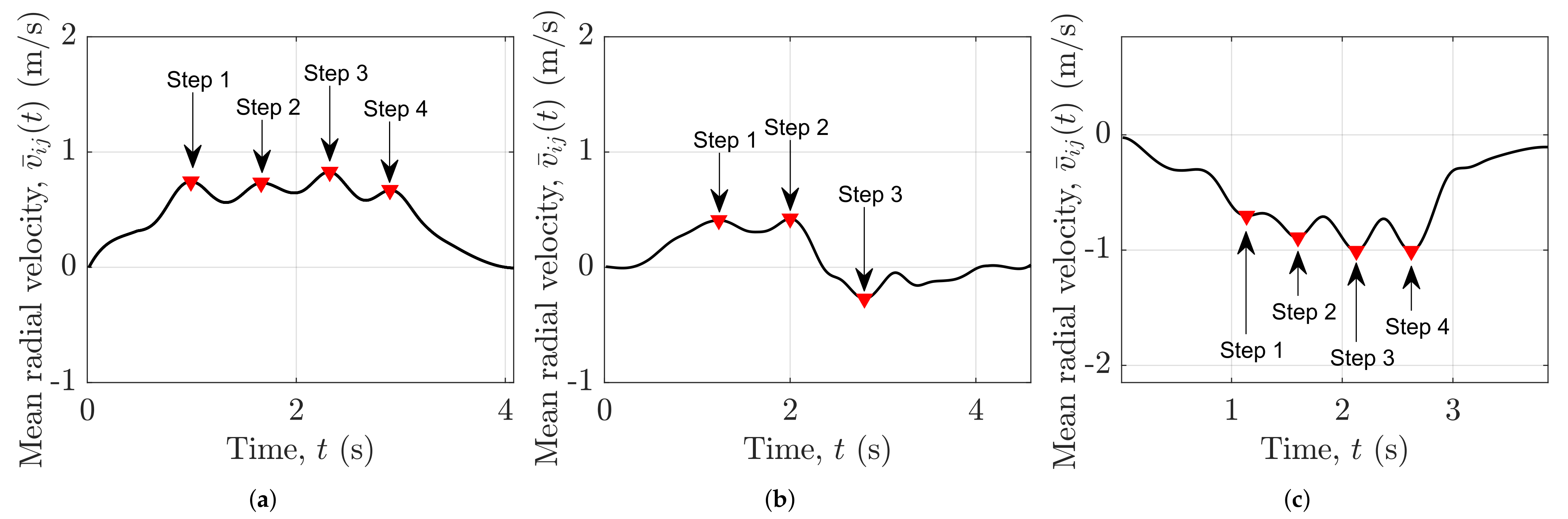
3.4. Implications on the Performance of an RF-Based Step Counter

In this subsection, we investigate how the SISO radar system affects the performance of an RF-based step counter under three different experimental scenarios. The radar-based passive step counter [49] was developed in order to count the number of steps in an unobtrusive manner for an SISO FMCW radar system. The authors of [49] compared the performance of their radar-based passive step counter with the wearable Garmin Forerunner 935 step counter. The reported accuracy of the radar-based passive step counter was more than 98%, which was similar to the accuracy of the Garmin Forerunner 935 step counter system. However, the walking activity of a person was restricted to merely Scenario 1, where a person would walk either towards or away from the SISO radar system. This restriction was naturally enforced by the limitations of the SISO radar system in the context of activity direction. In this section, the performance of the radar-based passive step counter is shown for Scenarios 1, 2, and 3.
To detect the number of steps in a particular walk activity, the SISO radar’s raw data are processed according to the block diagram shown in Figure 4. The Ancortek radar in a SISO configuration produces raw in-phase and quadrature (IQ) data for the wireless channel link  A i T x A j R x . The raw IQ data are processed by the radar signal preprocessing block (see Section 2) to generate the radial velocity distribution  p 11 ( v , t ) and mean radial velocity  v ¯ 11 ( t ) . The Savitzky–Golay smoothing filter [51] has been adopted to smooth the mean radial velocity  v ¯ 11 ( t ) using the MATLAB command “smooth(y,span,’sgolay’,degree)”, where “y” is the input vector or mean radial velocity vector v ¯ 11 ( t ) , “span” is the number of data points used for smoothing, “sgolay” is the Savitzky–Golay smoothing filter, and “degree” is the polynomial degree of the Savitzky–Golay filter. In our experiments, the “span” and “degree” are chosen to be 60 and 4, respectively.
The solid black curves in Figure 5a–c show the smoothed mean radial velocity v ¯ 11 ( t ) for Scenarios 1, 2, and 3, respectively. The smoothed mean radial velocity v ¯ 11 ( t ) is processed by the RF step detector to detect the number of steps and their corresponding timestamps. The detected steps of the RF step detector are distinctly marked and labeled in Figure 5. In Scenario 1, the human subject started walking from the position ( x 3 , y 2 ) and took four steps towards the position ( x 1 , y 2 ) . We can see from Figure 5a that the RF step detection algorithm has successfully detected the four steps. However, in Scenario 2, when the human subject walked with four steps from the position ( x 2 , y 3 ) towards the position ( x 2 , y 1 ) , the SISO radar system is unable to produce an intelligible walking activity signature. Consequently, the RF step detection algorithm is unable to detect all the steps that were taken by the human subject. Apparently, the RF step detector missed one of the four steps in Scenario 2 as shown in Figure 5b. Moreover, in Scenario 3, where a person walked from the position ( x 1 , y 1 ) towards the position ( x 3 , y 3 ) taking only four steps, the SISO radar system is able to produce a fair walking activity signature. Thus, the RF step detector is able to detect the four steps successfully as depicted in Figure 5c. Thus, we can conclude that the monostatic SISO radar system is not sufficient to capture the human micro-Doppler signatures with high precision in all directions.
It is now evident that the aforementioned limitations of the SISO radar system restrict the detection of the scatterer’s motion in the horizontal xy-plane. We must observe the environment from different perspectives to effectively detect the scatterer’s motion. Thus, we need a distributed RF sensing system to effectively determine the TV trajectories of the object under observation. For this reason, we propose to distribute at least two collocated transmitter–receiver antenna pairs in an indoor environment and preprocess the data for each wireless channel link (see Section 2 and Section 4). It should be mentioned that for SISO radar-based HAR systems, the classification accuracy will drop as the direction of the human motion relative to the radar’s boresight changes from parallel to perpendicular. Furthermore, as we increase the overall system complexity in the context of human activity classification, the performance of a machine learning or deep learning classifier is expected to further degrade for a SISO radar system. For instance, the system complexity is increased by classifying more than two kinds of activities such as falling, walking, sitting on a chair, and standing from a chair. We can now safely assert that a monostatic SISO radar system is not an apposite choice for direction-independent human activity detection.

4. Human Activity Signatures by Using a Distributed MIMO FMCW Radar System

The lack of the multi-perspective illumination of SISO radar systems is their major limitation, preventing the realization of a direction-independent HAR system (as described in Section 3). To overcome this limitation, we propose to utilize a MIMO radar system and distribute its antennas in an indoor environment to realize a direction-independent HAR system. We have distributed two pairs of collocated transmitter–receiver antennas to illuminate the indoor environment from different perspectives. For the sake of simplicity, we have limited the number of antennas to four, but the proposed approach can be straightforwardly scaled for a larger number of antennas. A separate radar signal preprocessing chain (as described in Section 2) has been adopted for each pair of collocated transmitter–receiver antennas. Thus, we have deployed a 2 × 2 MIMO radar system, which consists of two radar subsystems denoted as Radar 1 and Radar 2 . Radar 1 comprises a transmitter antenna A 1 T x and a receiver antenna A 1 R x . Analogously, Radar 2 consists of a transmitter antenna A 2 T x and a receiver antenna A 2 R x . We propose to position the two radar subsystems such that their boresight axes are orthogonal to each other, which enables the 2 × 2 MIMO radar system to effectively capture the scatterer motion in the horizontal xy-plane.
In this section, we mainly emphasize the impact of the direction of human activities on the TV radial velocity distribution p i i ( v , t ) of the link from A i T x to A i R x for i { 1 , 2 } . First, we discuss the measurement setup for the proposed 2 × 2 MIMO radar system. Second, three different experimental scenarios are illustrated in which the human activities are performed and analyzed. Third, we discuss the radial velocity distribution p i i ( v , t ) and mean radial velocity v ¯ i i ( t ) derived from measurements of the 2 × 2 MIMO radar system. Finally, the implications of different directions of human activities on the performance of an RF-based step counter are discussed.

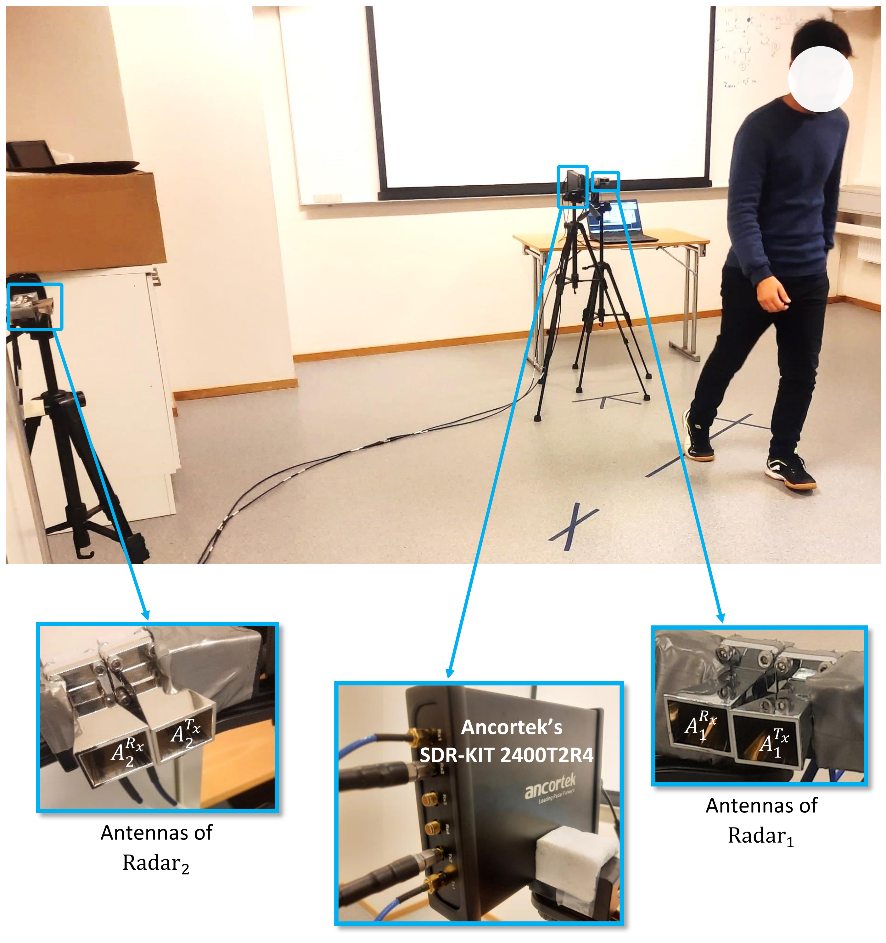
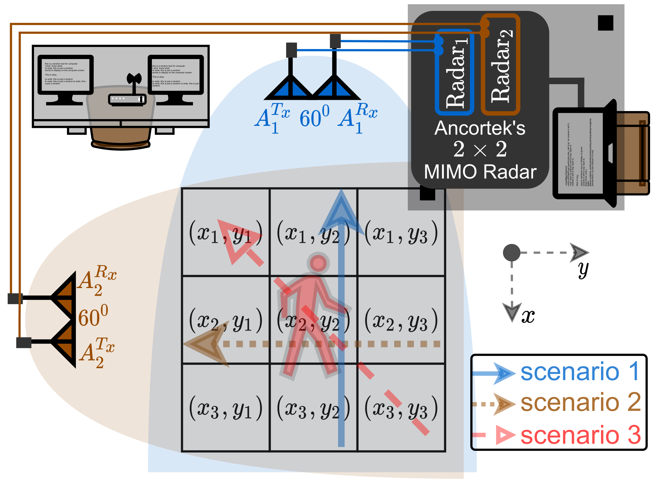
4.1. Measurement Setup

To realize the proposed distributed 2 × 2 MIMO radar configuration, we have used an FMCW mm-Wave radar operating at 24 GHz to capture the micro-Doppler information of a human body moving in the xy-plane. The MIMO FMCW radar system operating in the TDMA mode was configured according to the parameters listed in Table 2. For the Ancortek SDR-KIT 2400T2R4 radar system, we deployed RF cables with different lengths to avoid interchannel interference [47]. Owing to the TDMA mode of operation, the PRF of the 2 × 2 MIMO FMCW radar system is equal to 1/2 of the inverse of the chirp interval T s w ; i.e., PRF = 1 / ( 2 T s w ) . In TDMA mode, the transmitter antennas A 1 T x and A 2 T x of the radar subsystems Radar 1 and Radar 2 , respectively, transmit the chirp waveform c i ( t ) alternately and periodically in their respective time slot according to (2).
For the proposed distributed 2 × 2 MIMO configuration, the indoor environment remains exactly the same as described in Section 3. The activities of a person are observed in a laboratory cluttered with fixed objects such as electronics, chairs, tables, and other miscellaneous items, as shown in Figure 6. This Figure 6 also illustrates the actual experimental setup, where the placement of antennas shows a close resemblance to the proposed 2 × 2 distributed MIMO radar configuration depicted in Figure 7. The boresights of the two radar subsystems are orthogonal to each other, which enables the 2 × 2 MIMO radar system to capture the radial velocity distribution p i i ( v , t ) using (14) regardless the direction of activity. For practical reasons, we have marked the 2 × 2 MIMO radar’s operation region according to the field of view (FOV) of the two radar subsystems ( Radar 1 and Radar 2 ) as shown in Figure 6.

4.2. Scenarios of Human Activities
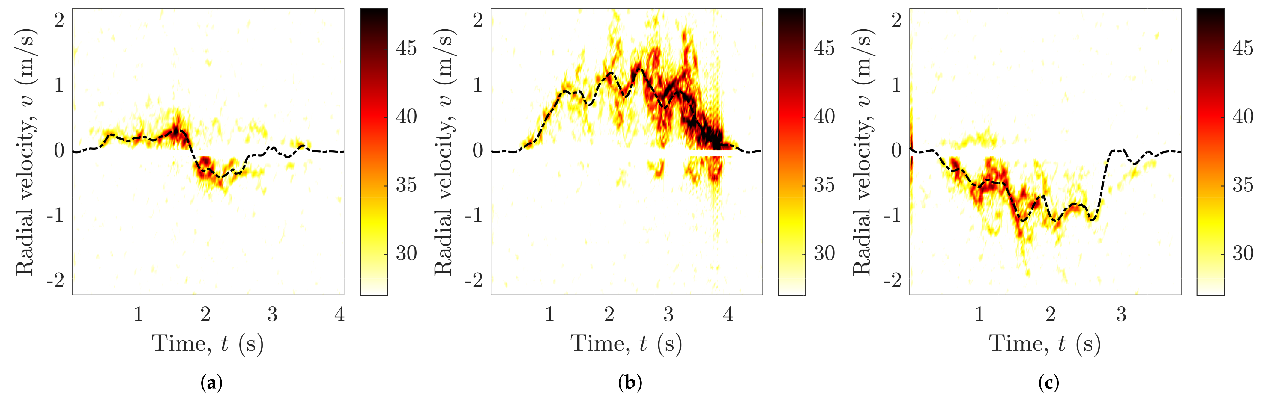
To overcome the limitations of the SISO radar system in terms of activity directions, we illuminate the environment from different perspectives via the proposed distributed 2 × 2 MIMO radar framework as shown in Figure 7. Recall that Radar i comprises a transmitter antenna A i T x and a receiver antenna A i R x ( i = 1 , 2 ) as illustrated in Figure 7. The two radar subsystems have a common illumination region as depicted by a 3 × 3 grid in Figure 7, which depends on the FOV and the maximum unambiguous range of the radar. This common area essentially limits the region of operation, within which all activities have to be performed. A moving human body under observation is illuminated from two different angles, as shown in Figure 7. This multi-perspective view helps us to overcome the limitations of the SISO radar system. For instance, if the subject moves in the direction parallel to the boresight of Radar 2 , then the Doppler frequencies measured with Radar 2 change considerably more over a larger range than the Doppler frequencies measured with Radar 1 . In this case, Radar 2 will detect the motion of the subject more effectively than Radar 1 . However, if the subject moves parallel to the Radar 1 boresight, then Radar 1 will obtain a much better micro-Doppler signature. The two radar subsystems in Figure 7 complement each other in the way that when the direction of motion changes from the x-axis to y-axis, the movement signature of the subject gradually disappears from the Radar 1 radial velocity distribution p 11 ( v , t ) and appears in the Radar 2 radial velocity distribution p 22 ( v , t ) .
To show the effectiveness of the proposed 2 × 2 MIMO scheme, we recorded the human motion in three different directions. In order to illustrate the direction of human motion in a particular experiment, we refer throughout this section to the 3 × 3 grid shown in Figure 7, in which three different scenarios of human movement are represented by different markings. The radial velocity distributions p 11 ( v , t ) and p 22 ( v , t ) of the two radar subsystems have been computed, and the results are delineated in the next subsection for a walking and falling activity of a person.

4.3. Results for the Proposed 2 × 2 MIMO Configuration

We have connected the Ancortek MIMO radar system with a signal processor, which processes the MIMO radar’s raw IQ data according to the method discussed in Section 2. For this research, we have recorded the radar’s raw IQ data for a 2 × 2 distributed MIMO radar system, and then we have processed the data offline using MATLAB. Identical but independent radar signal preprocessing chains are implemented for the two subchannels. For each human activity, we have computed the radial velocity distribution p i i ( v , t ) using (14) and mean radial velocity v ¯ i i ( t ) using (15) for i { 1 , 2 } . Figure 8 and Figure 9 correspond to Radar 2 , which show the TV radial velocity distribution p 22 ( v , t ) for the falling and walking activities, respectively. Note that, for the monostatic SISO configuration and 2 × 2 MIMO configuration in Section 3 and Section 4, respectively, the positions of the transmitter antenna A 1 T x and receiver antenna A 1 R x are identical. Therefore, Radar 1 of the 2 × 2 MIMO radar system is identical to the monostatic SISO radar system. As a consequence, the TV radial velocity distributions p 11 ( v , t ) corresponding to Radar 1 and the SISO radar system are the same. Recall that the TV radial velocity distributions p 11 ( v , t ) corresponding to Radar 1 are shown in Figure 2 and Figure 3 for the falling and walking activities, respectively. For all observed activities, we have also computed the mean radial velocity v ¯ i i ( t ) , which is represented by the black dashed line in Figure 2, Figure 3, Figure 8 and Figure 9. The falling and walking activities were performed in three different scenarios to see the effect of the human activity direction on the measured TV radial velocity distribution p i i ( v , t ) .
In Figure 7, we can see that the direction of movement is parallel to the boresight of Radar 1 and orthogonal to the boresight of Radar 2 for Scenario 1. To perform the walking activity in Scenario 1, the person walks from the position ( x 3 , y 2 ) towards the position ( x 1 , y 2 ) in a straight line. Similarly, to perform a falling activity, the person first stands still on the position ( x 3 , y 2 ) and then falls onto a mattress facing towards the antennas of Radar 1 . Figure 2a and Figure 8a show the impact of the falling activity on the measured TV radial velocity distributions p 11 ( v , t ) and p 22 ( v , t ) , respectively. For the walking activity, Figure 3a and Figure 9a show the measured TV radial velocity distributions p 11 ( v , t ) and p 22 ( v , t ) , respectively. Evidently from Figure 2a, Figure 8a, Figure 3a and Figure 9a, the 2 × 2 MIMO radar system is able to acquire good multi-perspective human activity signatures for Scenario 1. As the direction of the activity is towards Radar 1 in Scenario 1, it is obvious that Figure 2a and Figure 3a give better activity signatures than Figure 8a and Figure 9a, respectively.
The walking and falling activities are repeated for Scenario 2, where the initial and final positions are at ( x 2 , y 3 ) and ( x 2 , y 1 ) , respectively, as shown in Figure 7. Thus, the direction of motion in Scenario 2 is orthogonal to the boresight of Radar 1 and parallel to the boresight of Radar 2 . In Figure 2b and Figure 8b, the TV radial velocity distribution p i i ( v , t ) of the falling activity is shown for Radar 1 and Radar 2 , respectively. Analogously, Figure 3b and Figure 9b show the TV radial velocity distribution p i i ( v , t ) of the walking activity corresponding to Radar 1 and Radar 2 , respectively. From the measurement results, we can see that the distributed MIMO radar system captures good human activity signatures for Scenario 2 as well. For Scenario 2, as the direction of the activity is towards Radar 2 , we observe that Figure 8b and Figure 9b give better activity signatures than Figure 2b and Figure 3b, respectively. In other words, Radar 2 produces better human activity signatures than Radar 1 for Scenario 2.
In Scenario 3, the direction of movement is roughly diagonal to the boresights of Radar 1 and Radar 2 , as shown in Figure 7. For the human falling activity, the initial and final positions are ( x 3 , y 3 ) and ( x 1 , y 1 ) , respectively. This is in contrast to the walking activity, where the initial and final positions are ( x 1 , y 1 ) and ( x 3 , y 3 ) , respectively. Figure 2c and Figure 8c show the TV radial velocity distribution p i i ( v , t ) of the falling activity with respect to Radar 1 and Radar 2 . Analogously, Figure 3c and Figure 9c show the TV radial velocity distribution p i i ( v , t ) of the walking activity corresponding to Radar 1 and Radar 2 , respectively. Note that both Radar 1 and Radar 2 capture adequate human activity signatures for Scenario 3. It is evident from the measurement results that unlike the SISO radar system, the distributed MIMO radar system has the innate capability to provide better multi-perspective human activity signatures for all three scenarios.

4.4. Implications on the Performance of an RF-Based Step Counter

To illustrate the utility of the proposed distributed 2 × 2 MIMO radar system, we now investigate the performance of a radar-based passive step counter [49] for the MIMO configuration. As mentioned in Section 3, the radar-based passive step counter was designed only for human walking activities in accordance with Scenario 1. We have already shown the performance limitations of the SISO radar system with the radar-based passive step counter module in Section 3. In this section, we show how the integration of the radar-based passive step counter module with the proposed 2 × 2 MIMO radar system will mitigate the shortcomings that we encountered with the SISO radar system. Recall that illuminating the indoor environment from different perspectives, as shown in Figure 7, will enable the distributed 2 × 2 MIMO radar to capture the walking activity signature regardless of its direction.
A basic block diagram of the 2 × 2 MIMO radar-based RF step counter is shown in Figure 10, where it can be seen that the step counter module has been implemented separately for Radar 1 and Radar 2 . To detect the number of steps in a particular walking activity, the 2 × 2 MIMO radar’s raw IQ data are processed by the radar signal preprocessor module (see Section 2). The radar signal preprocessor module generates the TV mean radial velocities v ¯ 11 ( t ) and v ¯ 22 ( t ) for Radar 1 and Radar 2 , respectively. The TV mean radial velocity v ¯ i i ( t ) is smoothed by a Savitzky–Golay filter to be further processed by the RF step detection module.
In Figure 5 and Figure 11, the solid black curves show the smoothed TV mean radial velocities v ¯ 11 ( t ) and v ¯ 22 ( t ) for Radar 1 and Radar 2 , respectively. By processing the smoothed mean radial velocity v ¯ i i ( t ) , the RF step detection module detects the number of steps and their corresponding timestamps for the walking activity. The detected steps of the MIMO radar-based RF step detector are distinctly marked and labeled in Figure 5 and Figure 11 for Radar 1 and Radar 2 , respectively. For Scenario 1, the human subject started walking from the position ( x 3 , y 2 ) and took four steps towards the position ( x 1 , y 2 ) . We can see from Figure 5a that the RF step detection algorithm has successfully detected the four steps for the radar subsystem Radar 1 . However, the RF step detection algorithm has detected five steps in Figure 11a due to the poor quality of the data from Radar 2 . Thus, we can easily discard the data from Radar 2 and select the number of steps counted by the RF step counter associated with Radar 1 .
On the other hand, for Scenario 2, when the human subject walked with four steps from the position ( x 2 , y 3 ) towards the position ( x 2 , y 1 ) , Radar 2 is able to produce an intelligible walking activity signature. For Scenario 2, we can choose the results from the Radar 2 -based RF step counter, which accurately counts the number of steps, as shown in Figure 11b. Therefore, unlike the SISO-based RF step counter, the 2 × 2 MIMO-based RF step counter is able to detect all the steps that were taken by the human subject in Scenario 1 and 2. Moreover, for Scenario 3, when a person walked from the position ( x 1 , y 1 ) towards the position ( x 3 , y 3 ) taking only four steps, both radar systems Radar 1 and Radar 2 are able to produce good walking activity signatures. Thus, the RF step counter detects the four steps successfully as depicted in Figure 5c and Figure 11c for Scenario 3. It is now clear that by observing the environment from different perspectives, the proposed 2 × 2 MIMO radar system is able to detect the scatterer’s motion in the horizontal xy-plane. We can conclude that a distributed 2 × 2 MIMO radar system is sufficient to capture the human activity signatures in all directions.

5. Discussion

From the experimental results of Section 3 and Section 4, we can see that the proposed fundamental 2 × 2 MIMO radar system ameliorates the limitations posed by the SISO radar configuration. In Figure 2, Figure 3, Figure 8, and Figure 9, adequate falling and walking activity signatures were observed irrespective of the activity direction. Furthermore, to quantify and numerically assess the performance of the SISO and 2 × 2 MIMO radar systems for each scenario, we have computed the DTW [44] distance for the walking activity. A numerical analysis of the falling activity signatures yields similar results. Therefore, to be concise, we have only shown the performance of the SISO and 2 × 2 MIMO radar systems for the walking activity.
The DTW algorithm performs a time series analysis by evaluating the similarity between two temporal sequences. In this algorithm, the two temporal sequences are expanded or stretched such that the overall Euclidean distance between the two sequences is minimized, which makes the algorithm robust to any speed variations, accelerations, or decelerations in the data. This algorithm has been widely used in speech [52], gesture [53], and gait [54,55] recognition. To quantify whether a radar system has captured an adequate human activity signature or not, we first need a reference human activity signature for comparison. The reference activity signature is obtained in favorable conditions, where a person walks in the direction parallel to the boresight of the SISO radar. For each radar subsystem, the DTW distance is computed between the reference human activity signature and the captured human activity signature of a particular scenario. For the SISO radar system, equivalent to Radar 1 , we obtain a single DTW distance metric for each walking scenario as shown in the second and fourth columns of Table 3. However, for the proposed 2 × 2 MIMO radar system, we obtain two distinct DTW distance metrics, one for each radar subsystem ( Radar 1 and Radar 2 ). For the 2 × 2 MIMO radar system, the measured DTW distance metrics of Radar 1 and Radar 2 are compared, and the activity signature with the minimum DTW distance metric is chosen as shown in the last column of Table 3. Note that the radar subsystem with the minimum DTW distance is chosen because its signature would resemble the higher similarity to the reference activity signature.
A performance summary of the SISO and 2 × 2 MIMO radar system is based on the results shown in Table 3. It is clear that the SISO radar system is unable to obtain an adequate activity signature in Scenario 2 as its DTW distance is very large (see the underlined DTW distance metric in Table 3). Unlike the SISO radar system, the 2 × 2 MIMO radar system is able to perform well in all three scenarios, as evident from the measured DTW distances and the results from Section 3 and Section 4.
Although we have presented the basic 2 × 2 distributed MIMO radar system to successfully capture the human activity signature in all directions, this study does not include a machine learning or deep learning-based classification network to recognize the type of human activity. However, an RF-based direction-independent HAR system using the proposed MIMO radar configuration would be considered as an extension of this research. To develop such a direction-independent HAR system, the data observed by Radar 1 and Radar 2 need to be merged or fused together. As previous studies have shown the performance improvements due to the fusion of the data obtained from either homogeneous sensors [17,56] or heterogeneous sensors [9], we can expect to achieve similar performance gains by fusing the data of Radar 1 and Radar 2 . In all likelihood, the TV radial velocity distribution p i i ( v , t ) generated by the proposed 2 × 2 MIMO radar system would ameliorate the classification performance upon appropriate data fusion. Therefore, a learning network based on the proposed 2 × 2 MIMO radar data would be able to recognize different activities in different directions.
For a computationally efficient machine learning algorithm, we can extract multiple features from the TV radial velocity distributions p 11 ( v , t ) and p 22 ( v , t ) . For instance, we have computed a key parameter known as TV mean radial velocity v ¯ i i ( t ) , which is shown by the black dashed line in Figure 2, Figure 3, Figure 8, and Figure 9. Higher-order parameters and features can be readily computed for the data obtained from the proposed 2 × 2 MIMO radar system. Alternatively, a separate convolutional neural network (CNN) [57] may be adopted to extract features from the data of Radar 1 and Radar 2 . Then, the obtained features corresponding to Radar 1 and Radar 2 can be merged using a deep neural network for the classification of human activity. Conceivably, the proposed 2 × 2 MIMO solution combined with a machine learning or deep learning-based classifier would mitigate the concerns regarding a direction-independent HAR system.

6. Conclusions

We have proposed a fundamental 2 × 2 MIMO approach to analyze the radial velocity distribution and mean radial velocity for falling and walking activities. We confirmed the limitations of SISO RF sensing and emphasized the importance of a distributed MIMO RF system in the context of different directions of human activities. Unlike the state-of-the-art monostatic SISO or MIMO radar systems, our proposed 2 × 2 distributed MIMO radar system enables the realization of a direction-independent HAR system using TV channel characteristics of human activities obtained from different aspect angles. A comparison with the performance of a radar-based passive step counter has been demonstrated for a SISO and a proposed 2 × 2 MIMO radar system. It is shown that the 2 × 2 MIMO radar-based step counter is able to accurately detect the number of walking steps in all scenarios, while the SISO radar-based step counter fails to perform. Moreover, the DTW distance metric is used to numerically assess the performance of the SISO and 2 × 2 MIMO radar systems.
Although the fundamental approach presented in this paper may be adopted for various applications, we plan to extend this work to a direction-independent HAR system, where we intend to increase the overall performance of the RF-based HAR system by increasing the number of antennas. The proposed 2 × 2 MIMO radar system can straightforwardly be scaled to an N × N MIMO radar system. Moreover, from the obtained multi-perspective channel characteristics, multiple features can be extracted for a classical machine learning-based HAR system. For a more complex HAR problem, a deep CNN can be adopted based on the data from the proposed distributed MIMO radar framework.

Author Contributions

Conceptualization and methodology, S.W., M.M., and M.P.; software, S.W. and M.M.; validation and formal analysis, S.W., M.M., and M.P.; investigation, resources, and data curation, S.W. and M.M.; writing—original draft preparation, S.W. and M.M.; writing—review and editing, S.W. and M.P.; visualization, S.W.; supervision and funding acquisition, M.P. All authors have read and agreed to the published version of the manuscript.

Funding

This work has been carried out within the scope of the CareWell project funded by the Research Council of Norway under the grant number 300638.

Institutional Review Board Statement

Not applicable.

Informed Consent Statement

Not applicable.

Data Availability Statement

The authors may provide the presented measurement data upon request.

Conflicts of Interest

The authors declare no conflict of interest.

References

  1. Al-khafajiy, M.; Baker, T.; Chalmers, C.; Asim, M.; Kolivand, H.; Fahim, M.; Waraich, A. Remote health monitoring of elderly through wearable sensors. Multimed. Tools Appl. 2019, 78, 24681–24706. [Google Scholar] [CrossRef] [Green Version]
  2. Kim, K.; Jalal, A.; Mahmood, M. Vision-based human activity recognition system using depth silhouettes: A smart home system for monitoring the residents. J. Electr. Eng. Technol. 2019, 14, 2567–2573. [Google Scholar] [CrossRef]
  3. Rashmi, M.; Ashwin, T.S.; Guddeti, R.M.R. Surveillance video analysis for student action recognition and localization inside computer laboratories of a smart campus. Multimed. Tools Appl. 2021, 80, 2907–2929. [Google Scholar] [CrossRef]
  4. Gurcan, F.; Cagiltay, N.E.; Cagiltay, K. Mapping human–computer interaction research themes and trends from its existence to today: A topic modeling-based review of past 60 years. Int. J. Hum.-Comput. Interact. 2021, 37, 267–280. [Google Scholar] [CrossRef]
  5. Tuncer, T.; Ertam, F.; Dogan, S.; Subasi, A. An automated daily sports activities and gender recognition method based on novel multikernel local diamond pattern using sensor signals. IEEE Trans. Instrum. Meas. 2020, 69, 9441–9448. [Google Scholar] [CrossRef]
  6. Tammvee, M.; Anbarjafari, G. Human activity recognition-based path planning for autonomous vehicles. Signal Image Video Process. 2021, 15, 809–816. [Google Scholar] [CrossRef]
  7. Rodriguez Lera, F.J.; Martín Rico, F.; Guerrero Higueras, A.M.; Olivera, V.M. A context-awareness model for activity recognition in robot-assisted scenarios. Expert Syst. 2020, 37, e12481. [Google Scholar] [CrossRef]
  8. Muaaz, M.; Chelli, A.; Pätzold, M. WiHAR: From Wi-Fi channel state information to unobtrusive human activity recognition. In Proceedings of the 2020 IEEE Vehicular Technology Conference, Antwerp, Belgium, 25–28 May 2020. [Google Scholar] [CrossRef]
  9. Muaaz, M.; Chelli, A.; Abdelgawwad, A.A.; Mallofre, A.C.; Pätzold, M. WiWeHAR: Multimodal human activity recognition using Wi-Fi and wearable sensing modalities. IEEE Access 2020, 8, 164453–164470. [Google Scholar] [CrossRef]
  10. Wang, W.; Liu, A.X.; Shahzad, M.; Ling, K.; Lu, S. Device-free human activity recognition using commercial WiFi devices. IEEE J. Sel. Areas Commun. 2017, 35, 1118–1131. [Google Scholar] [CrossRef]
  11. Erol, B.; Amin, M.G. Radar data cube processing for human activity recognition using multisubspace learning. IEEE Trans. Aerosp. Electron. Syst. 2019, 55, 3617–3628. [Google Scholar] [CrossRef]
  12. Wang, W.; Liu, A.X.; Shahzad, M.; Ling, K.; Lu, S. Understanding and modeling of WiFi signal based human activity recognition. In Proceedings of the 21st Annual International Conference on Mobile Computing and Networking, Paris, France, 7–11 September 2015; pp. 65–76. [Google Scholar]
  13. Wang, W.; Liu, A.X.; Shahzad, M. Gait recognition using WiFi signals. In Proceedings of the 2016 ACM International Joint Conference on Pervasive and Ubiquitous Computing, Heidelberg, Germany, 12–16 September 2016; pp. 363–373. [Google Scholar]
  14. Ding, C.; Hong, H.; Zou, Y.; Chu, H.; Zhu, X.; Fioranelli, F.; Le Kernec, J.; Li, C. Continuous human motion recognition with a dynamic range-Doppler trajectory method based on FMCW radar. IEEE Trans. Geosci. Remote Sens. 2019, 57, 6821–6831. [Google Scholar] [CrossRef]
  15. Waqar, S.; Yusaf, H.; Sana, S.; Waqas, M.; Siddiqui, F.A. Reconfigurable monopulse radar tracking processor. In Proceedings of the 2018 15th International Bhurban Conference on Applied Sciences and Technology (IBCAST), Islamabad, Pakistan, 9–13 January 2018; pp. 805–809. [Google Scholar]
  16. Amin, M.G.; Zhang, Y.D.; Ahmad, F.; Ho, K.C.D. Radar signal processing for elderly fall detection: The future for in-home monitoring. IEEE Signal Process. Mag. 2016, 33, 71–80. [Google Scholar] [CrossRef]
  17. Erol, B.; Amin, M.G.; Boashash, B. Range-Doppler radar sensor fusion for fall detection. In Proceedings of the 2017 IEEE Radar Conference (RadarConf), Seattle, WA, USA, 8–12 May 2017; pp. 819–824. [Google Scholar]
  18. Fioranelli, F.; Ritchie, M.; Griffiths, H. Aspect angle dependence and multistatic data fusion for micro-Doppler classification of armed/unarmed personnel. IET Radar Sonar Navig. 2015, 9, 1231–1239. [Google Scholar] [CrossRef] [Green Version]
  19. Louf, V.; Protat, A.; Warren, R.A.; Collis, S.M.; Wolff, D.B.; Raunyiar, S.; Jakob, C.; Petersen, W.A. An integrated approach to weather radar calibration and monitoring using ground clutter and satellite comparisons. J. Atmos. Ocean. Technol. 2019, 36, 17–39. [Google Scholar] [CrossRef] [Green Version]
  20. Watts, S. The ASV 21 maritime surveillance radar. In Proceedings of the 2017 IEEE Radar Conference (RadarConf), Seattle, WA, USA, 8–12 May 2017; pp. 27–32. [Google Scholar] [CrossRef]
  21. Xiaodong, L.; Koga, T. DAPS based adaptive tracking system for high-assurance air traffic surveillance. In Proceedings of the 2014 Integrated Communications, Navigation and Surveillance Conference (ICNS) Conference Proceedings, Herndon, VA, USA, 8–10 April 2014; pp. 1–4. [Google Scholar] [CrossRef]
  22. Nguyen, D.A.; Cho, B.; Seo, C.; Park, J.; Lee, D.H. Analysis of the optimal frequency band for a ballistic missile defense radar system. J. Electromagn. Eng. Sci. 2018, 18, 231–241. [Google Scholar] [CrossRef] [Green Version]
  23. Gómez-del Hoyo, P.J.; Del-Rey-Maestre, N.; Mata-Moya, D.; Jarabo-Amores, M.P.; Benito-Ortiz, M.C. Coherent detection and 3D tracking stages of a DVB-T based passive radar for terrestrial traffic monitoring. In IOP Conference Series: Materials Science and Engineering; IOP Publishing: Bristol, UK, 2019; Volume 524, p. 012002. [Google Scholar] [CrossRef]
  24. Bandini, F.; Sunding, T.P.; Linde, J.; Smith, O.; Jensen, I.K.; Köppl, C.J.; Butts, M.; Bauer-Gottwein, P. Unmanned Aerial System (UAS) observations of water surface elevation in a small stream: Comparison of radar altimetry, LIDAR and photogrammetry techniques. Remote Sens. Environ. 2020, 237, 111487. [Google Scholar] [CrossRef]
  25. Frigeri, A.; Ercoli, M. The ScanMars subsurface radar sounding experiment on AMADEE-18. Astrobiology 2020, 20, 1338–1352. [Google Scholar] [CrossRef]
  26. Margot, J.L. A Data-Taking System for Planetary Radar Applications. J. Astron. Instrum. 2021, 10. [Google Scholar] [CrossRef]
  27. Waldschmidt, C.; Hasch, J.; Menzel, W. Automotive Radar—From First Efforts to Future Systems. IEEE J. Microw. 2021, 1, 135–148. [Google Scholar] [CrossRef]
  28. Liu, Z.; Cai, Y.; Wang, H.; Chen, L.; Gao, H.; Jia, Y.; Li, Y. Robust target recognition and tracking of self-driving cars with radar and camera information fusion under severe weather conditions. IEEE Trans. Intell. Transp. Syst. 2021, 1–14. [Google Scholar] [CrossRef]
  29. Uysal, F. Phase-coded FMCW automotive radar: System design and interference mitigation. IEEE Trans. Veh. Technol. 2020, 69, 270–281. [Google Scholar] [CrossRef] [Green Version]
  30. Kranold, L.; Taherzadeh, M.; Nabki, F.; Coates, M.; Popovic, M. Microwave breast screening prototype: System miniaturization with IC pulse radio. IEEE J. Electromagn. RF Microw. Med. Biol. 2021, 5, 168–178. [Google Scholar] [CrossRef]
  31. Du, H.; Jin, T.; He, Y.; Song, Y.; Dai, Y. Segmented convolutional gated recurrent neural networks for human activity recognition in ultra-wideband radar. Neurocomputing 2020, 396, 451–464. [Google Scholar] [CrossRef]
  32. Li, X.; He, Y.; Jing, X. A survey of deep learning-based human activity recognition in radar. Remote Sens. 2019, 11, 1068. [Google Scholar] [CrossRef] [Green Version]
  33. Luo, F.; Poslad, S.; Bodanese, E. Human activity detection and coarse localization outdoors using micro-Doppler signatures. IEEE Sens. J. 2019, 19, 8079–8094. [Google Scholar] [CrossRef]
  34. Jokanovic, B.; Amin, M. Fall detection using deep learning in range-Doppler radars. IEEE Trans. Aerosp. Electron. Syst. 2018, 54, 180–189. [Google Scholar] [CrossRef]
  35. Liu, L.; Popescu, M.; Skubic, M.; Rantz, M.; Yardibi, T.; Cuddihy, P. Automatic fall detection based on Doppler radar motion signature. In Proceedings of the 2011 5th International Conference on Pervasive Computing Technologies for Healthcare (PervasiveHealth) and Workshops, Dublin, Ireland, 23–26 May 2011; pp. 222–225. [Google Scholar]
  36. Liu, L.; Popescu, M.; Ho, K.C.; Skubic, M.; Rantz, M. Doppler radar sensor positioning in a fall detection system. In Proceedings of the 2012 Annual International Conference of the IEEE Engineering in Medicine and Biology Society, San Diego, CA, USA, 28 August–1 September 2012; pp. 256–259. [Google Scholar]
  37. Sana, S.; Waqar, S.; Yusaf, H.; Waqas, M.; Siddiqui, F.A. Software defined digital beam forming processor. In Proceedings of the 13th International Bhurban Conference on Applied Sciences and Technology, IBCAST 2016, Islamabad, Pakistan, 12–16 January 2016; pp. 671–676. [Google Scholar] [CrossRef]
  38. Molchanov, P.; Gupta, S.; Kim, K.; Pulli, K. Short-range FMCW monopulse radar for hand-gesture sensing. In Proceedings of the IEEE National Radar Conference-Proceedings, Arlington, VA, USA, 10–15 May 2015; pp. 1491–1496. [Google Scholar] [CrossRef]
  39. Wang, G.; Gu, C.; Inoue, T.; Li, C. A hybrid FMCW-interferometry radar for indoor precise positioning and versatile life activity monitoring. IEEE Trans. Microw. Theory Tech. 2014, 62, 2812–2822. [Google Scholar] [CrossRef]
  40. Jian, M.; Lu, Z.; Chen, V.C. Drone detection and tracking based on phase-interferometric Doppler radar. In Proceedings of the 2018 IEEE Radar Conference (RadarConf18), Oklahoma City, OK, USA, 23–27 April 2018; pp. 1146–1149. [Google Scholar]
  41. Kim, S.; Kim, B.S.; Jin, Y.; Lee, J. Extrapolation-RELAX estimator based on spectrum partitioning for DOA estimation of FMCW radar. IEEE Access 2019, 7, 98771–98780. [Google Scholar] [CrossRef]
  42. Fioranelli, F.; Ritchie, M.; Griffiths, H. Bistatic human micro-Doppler signatures for classification of indoor activities. In Proceedings of the 2017 IEEE Radar Conference (RadarConf), Seattle, WA, USA, 8–12 May 2017; pp. 610–615. [Google Scholar]
  43. Abuduaini, A.; Shiraki, N.; Honma, N.; Nakayama, T.; Iizuka, S. Performance evaluation of multiple human-body localization using bistatic MIMO radar. In Proceedings of the 2019 IEEE Asia-Pacific Microwave Conference (APMC), Singapore, 10–13 December 2019; pp. 575–577. [Google Scholar]
  44. Berndt, D.J.; Clifford, J. Using dynamic time warping to find patterns in time series. In Proceedings of the 94 Workshop on Knowledge Discovery in Databases, Seattle, WA, USA, 31 July–1 August 1994; Volume 10, pp. 359–370. [Google Scholar]
  45. Bekar, M.; Baker, C.J.; Hoare, E.G.; Gashinova, M. Joint MIMO radar and communication system using a PSK-LFM waveform with TDM and CDM approaches. IEEE Sens. J. 2021, 21, 6115–6124. [Google Scholar] [CrossRef]
  46. Chen, V.C. The Micro-Doppler Effect in Radar; Artech House: Norwood, MA, USA, 2019; p. 174. [Google Scholar]
  47. Waqar, S.; Pätzold, M. Interchannel interference and mitigation in distributed MIMO RF sensing. Sensors 2021, 21, 7496. [Google Scholar] [CrossRef]
  48. Lulu, A.; Mobasseri, B.G. High-resolution range-Doppler maps by coherent extension of narrowband pulses. IEEE Trans. Aerosp. Electron. Syst. 2020, 56, 3099–3112. [Google Scholar] [CrossRef]
  49. Muaaz, M.; Waqar, S.; Matthias, P. Radar-based passive step counter and its comparison with a wrist-worn physical activity tracker. In Proceedings of the 4th International Conference on Intelligent Technologies and Applications INTAP 2021, Grimstad, Norway, 11–13 October 2021. [Google Scholar]
  50. Abdelgawwad, A.; Borhani, A.; Pätzold, M. Modelling, analysis, and simulation of the micro-Doppler effect in wideband indoor channels with confirmation through pendulum experiments. Sensors 2020, 20, 1049. [Google Scholar] [CrossRef] [PubMed] [Green Version]
  51. Savitzky, A.; Golay, M.J.E. Smoothing and differentiation of data by simplified least squares procedures. Anal. Chem. 1964, 36, 1627–1639. [Google Scholar] [CrossRef]
  52. Ismail, A.; Abdlerazek, S.; El-Henawy, I.M. Development of smart healthcare system based on speech recognition using support vector machine and dynamic time warping. Sustainability 2020, 12, 2403. [Google Scholar] [CrossRef] [Green Version]
  53. Fugini, M.; Finocchi, J.; Trasa, G. Gesture recognition using dynamic time warping. In Proceedings of the Workshop on Enabling Technologies: Infrastructure for Collaborative Enterprises, Virtual, 10–13 September 2020; pp. 279–282. [Google Scholar] [CrossRef]
  54. Muaaz, M.; Mayrhofer, R. Smartphone-based gait recognition: From authentication to imitation. IEEE Trans. Mob. Comput. 2017, 16, 3209–3221. [Google Scholar] [CrossRef]
  55. Muaaz, M.; Mayrhofer, R. Orientation independent cell phone based gait authentication. In Proceedings of the 12th International Conference on Advances in Mobile Computing and Multimedia, MoMM 2014, Kaohsiung, Taiwan, 8–10 December 2014; pp. 161–164. [Google Scholar] [CrossRef]
  56. Chen, Z.; Li, G.; Fioranelli, F.; Griffiths, H. Personnel recognition and gait classification based on multistatic micro-Doppler signatures using deep convolutional neural networks. IEEE Trans. Geosci. Remote Sens. Lett. 2018, 15, 669–673. [Google Scholar] [CrossRef] [Green Version]
  57. Muaaz, M.; Chelli, A.; Gerdes, M.W.; Pätzold, M. Wi-Sense: A passive human activity recognition system using Wi-Fi and convolutional neural network and its integration in health information systems. Ann. Telecommun. 2021, 1–13. [Google Scholar] [CrossRef]
Figure 1. A SISO radar system in the presence of a moving person in a cluttered indoor environment.
Applsci 12 01825 g001
Figure 2. For a SISO radar system, the measured radial velocity distribution p 11 ( v , t ) and mean radial velocity v ¯ 11 ( t ) of a human falling activity for (a) Scenario 1, (b) Scenario 2, and (c) Scenario 3.
Applsci 12 01825 g002
Figure 3. For a SISO radar system, the measured radial velocity distribution p 11 ( v , t ) and mean radial velocity v ¯ 11 ( t ) of a human walking activity for (a) Scenario 1, (b) Scenario 2, and (c) Scenario 3.
Applsci 12 01825 g003
Figure 4. The block diagram of the RF-based step counter for a SISO radar system.
Applsci 12 01825 g004
Figure 5. For a SISO radar, the number of steps detected from the smoothed mean radial velocity v ¯ 11 ( t ) of a human walking activity according to (a) Scenario 1, (b) Scenario 2, and (c) Scenario 3.
Applsci 12 01825 g005
Figure 6. The distributed 2 × 2 MIMO radar setup in the presence of a moving person walking in an indoor environment.
Applsci 12 01825 g006
Figure 7. Two radar subsystems forming a 2 × 2 distributed MIMO radar system in the presence of a moving person in a cluttered indoor environment.
Applsci 12 01825 g007
Figure 8. For Radar 2 , the measured radial velocity distribution p 22 ( v , t ) and mean radial velocity v ¯ 22 ( t ) of a human falling activity in (a) Scenario 1, (b) Scenario 2, and (c) Scenario 3.
Applsci 12 01825 g008
Figure 9. For Radar 2 , the measured radial velocity distribution p 22 ( v , t ) and mean radial velocity v ¯ 22 ( t ) of a human walking activity in (a) Scenario 1, (b) Scenario 2, and (c) Scenario 3.
Applsci 12 01825 g009
Figure 10. The block diagram of the RF-based step counter for a 2 × 2 MIMO radar system.
Applsci 12 01825 g010
Figure 11. For Radar 2 , the number of steps detected from the smoothed mean radial velocity v ¯ 22 ( t ) of a human walking activity according to (a) Scenario 1, (b) Scenario 2, and (c) Scenario 3.
Applsci 12 01825 g011
Table 1. System parameters of the SISO experimental setup.
DescriptionSymbolsValues
RF cable lengths ( L 1 T x , L 1 R x ) ( 0.3 , 0.3 ) m
Carrier frequency f c 24.125 GHz
Radar’s bandwidth BW 250 MHz
Sweep time T s w 500 μ s
Pulse repetition freq. PRF 2 kHz
Table 2. System parameters of the 2 × 2 MIMO experimental setup.
DescriptionSymbolsValues
RF cable lengths ( L 1 T x , L 1 R x , L 2 T x , L 2 R x ) ( 0.3 , 0.3 , 7 , 7 ) m
Carrier frequency f c 24.125 GHz
Radar’s bandwidth BW 250 MHz
Sweep time T s w 500 μ s
Pulse repetition freq. PRF 1 kHz
Table 3. The DTW distance metric for the SISO and 2 × 2 MIMO radar systems.
ScenarioDist. ofDist. ofDist. ofDist. of 2 × 2
# Radar 1 Radar 2 SISO RadarMIMO Radar
1 19.6 81.2 19.6 19.6
2 73.8 12.0 73.8 12.0
3 7.3 9.1 7.3 7.3
Publisher’s Note: MDPI stays neutral with regard to jurisdictional claims in published maps and institutional affiliations.

