Abstract
In the current manuscript, we aimed to evaluate the application of aerated concrete blocks for the construction of single-family homes in Guayaquil, Ecuador, through a comparison with conventional materials. The design of the structural elements was carried out according to the NEC-2015 and ACI 318-14 standards, in which a 36% reduction in the dead load of the structure was achieved by using aerated concrete blocks in the masonry of the house. With a life cycle analysis, a quantification of the most relevant impacts generated during the production and construction phases was obtained. In this way, the most contributing process was found to be the clinker production, generating 7998 kgCO2-Eq. for traditional housing, and 5113 kgCO2-Eq. for non-traditional housing, thus reaching a difference of 36%. Therefore, it was shown that the use of lower-density materials is viable and, due to their easy and fast application, allows for a reduction of up to 10% in the project execution time; a savings of 10% in the total cost, in addition, evidences its potential to access sustainable construction in Ecuador.
1. Introduction
Construction is one of the industries characterized by a high demand for energy consumption and available natural resources. It is estimated that 2 tons of raw materials are needed per square meter of construction, requiring a significant investment of resources in order to obtain, transport, and manufacture them [1]. According to the Global Status Report for Buildings and Construction published by GlobalABC in 2019 [2], the construction sector accounts for 39% of global energy-related CO2 emissions, 30% of the extraction of raw materials in the environment, 25% of the generation of solid waste, and 25% of the consumption of water.
The investigations of construction materials that have been carried out recently have made it possible to develop new technologies corresponding to the production of low-density concrete to be used in masonry or prefabricated elements [3]. The savings in construction time and the ease of installation that would result from their application in prefabricated walls or floors and their more resistant or similar (depending on its use) behavior, compared to conventional materials, is currently unknown. Since Ecuador is a country with high seismic risk, selecting the materials to be used in construction is a requirement to avoid damage to both structural and masonry elements.
For this reason, in Ecuador, sustainable construction is presented as a challenge to be achieved, which is a balance between environmental impact, social impact, and economic sustainability [4]. In addition, this sector is a determining factor in the economy of Ecuador since it has come to represent, in 2019, 8.17% of the country’s real Gross Domestic Product [5]. Among the materials that predominate in the construction of a structure, reinforced concrete represents 91.8%, while wood, metal, and others represent less than 6% each. Likewise, blocks and bricks are the most-used materials for elaborating walls, representing 61.6% and 35.1%, respectively [6].
The most representative characteristics of concrete, such as its versatility, durability, sustainability, and economy, have made it the most widely used construction material worldwide [3]. Additionally, it offers high compressive strengths but low tensile strengths (in the order of 10%). Still, the technology developed for concrete has allowed it to compete with steel constructions by having rods in the identified areas for traction, thus creating reinforced concrete which, unlike natural stones, consists of an artificial material that is resistant to both traction and bending forces.
Hydraulic cement, in turn, must meet the performance requirements established in the NTE INEN 2380 standard [7]. Its classification is based on specific properties without considering the restrictions on its composition. On the other hand, aggregates give concrete the property of volumetric stability, contribute to reducing cracks produced by concrete moisture, and impart resistance to wear, allowing its use in hydraulic structures and trafficked surfaces, among others [8]. In addition, the prediction of the elasto-viscoplastic properties of a high-performance concrete (HPC) is possible by means of a multiscale numerical homogenization method, which is divided into two levels according to HPC: the level of mortar and the level of concrete [9,10,11].
In the construction industry, several materials predominate; among them is wood, which is a resource obtained from nature using machinery that is responsible for treating it to obtain the final product. Even though Ecuador has developed a great timber tradition, the machinery, apparatus, and tools for its production are scarce. Ecuadorian companies dedicated to distributing this construction material follow three phases for its production [12].
As a necessity to the rapid growth of the construction sector, around the year 1960, the production of lightweight concrete appeared, initially being used in slabs and ceilings; this is why, in countries of the European continent, the development and use of this product began with the addition of foams, which gave rise to cellular mortars. With time, this type of concrete has been modified according to the needs that arise, such as economic and energy savings [13], thus achieving densities of less than 2000 kg/m3.
The fundamental goal of this industry is to optimize the execution time of a project as well as its corresponding economic value. Therefore, in this article, through comparison, the structural and environmental benefits were obtained by using unconventional materials in construction. In this way, the main objective was to evaluate the application of low-density concrete blocks in the masonry of single-family homes through a comparison with conventional materials.
In 2019, the first specific study of the water footprint, considering the construction stage of residential developments in Spain, was carried out in such a way that it is taken as a starting reference for deepening analyses of the environmental impacts of this activity. The study took, as a practical application, a specific development made by Vía Célere to serve as a reference that could be extrapolated to other similar buildings [14].
Santos Corzo, in a study on the life cycle analysis of a family home in the city of Huancayo, demonstrated, by comparing two systems, that a higher primary energy consumption and generation of environmental loads follow when concrete blocks are used instead of clay bricks. Identifying and evaluating opportunities to reduce environmental impacts throughout the life cycle were the main objectives of this study [15].
The hypothesis to be defended is based on the construction benefits that would result from using lightweight concrete blocks as masonry for houses in Ecuador due to the reduction in the amount of concrete and steel in structural and non-structural elements. In summary, the objective of this work is to evaluate the application of low-density concrete blocks for the construction of single-family homes through a comparison with conventional materials, to analyze data from laboratory tests (dry density of concrete blocks) so as to determine the loads that will be applied in the family home to carry out its structural design, and finally, to apply the life cycle analysis methodology to measure the environmental impact and establish new solutions in the construction sector.
2. Materials and Methods
2.1. Materials
The structural design of two houses will be carried out with the same characteristics (single-family with two floors, 5.09-m high and 42 m2), but using different materials for the construction of exterior walls: conventional (dimensions of 40 cm × 20 cm × 20 cm, by the provisions of NTE INEN 638 [16]) and aerated concrete blocks (dimensions of 61 cm × 20 cm × 5 cm), considering a density of 1.73 and 0.45 ton/m3, respectively.
At the Innovation Center located at the San Eduardo Plant in Holcim, Ecuador, S.A., the dosages of the mixtures were made for the elaboration of the traditional and aerated concrete blocks. The aerated concrete mix, also known as autoclaved aerated concrete (AAC), is manufactured from materials such as cement, water, additives, and preformed foam, and without the use of coarse aggregates. This mixture is prepared in two simultaneous phases: slurry (slurry formed by cement, water, and additives) and foam (a mixture between water and high-stability active tensile; when air is provided, foam is formed). From this mixture (Table 1), the blocks are molded prismatically without holes inside, unlike blocks made with conventional concrete. On the other hand, the conventional concrete mix uses cement, aggregates, gravel, volcanic granules, pumice stone, slag, or other inert inorganic materials (Table 1).

Table 1.
Percentage dosage of conventional and autoclaved aerated concrete mix.
2.2. Structural Design
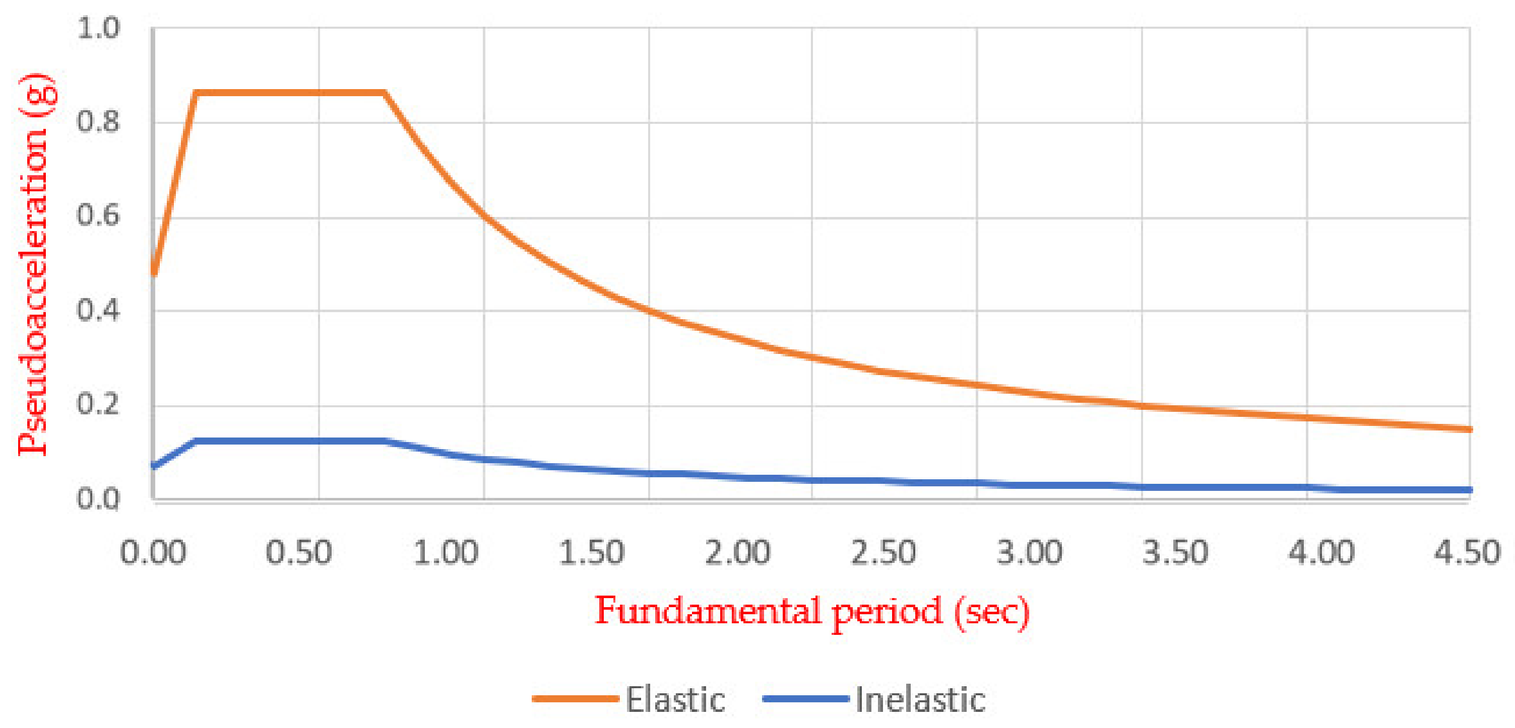
The structural elements such as columns, beams, slabs, plinths, and stairs were designed under the criteria presented in the NEC-SE-DS code (Seismic Hazard—Earthquake-Resistant Design of the Ecuadorian Construction Standard [17]) and considering the Regulation Requirements for Structural Concrete according to the American Institute of Concrete [18]. The criteria for earthquake-resistant designs include determining the elastic design spectrum; in this specific case, the north of Guayaquil was identified as the area where the house will be built, and through the seismic zoning map, the zone factor was determined, and the coefficients of the soil profile were defined, categorizing it as soil type D. For the design of a house, an importance coefficient of 1.0 was considered (it is not an essential or special occupancy structure), 0.90 for the irregularity in plant (the second floor has a cantilever that will be used as a balcony), and 0.96 due to minor irregularities in elevation (i.e., because the heights of the first and second floors differ by 6%). The inelastic and elastic response spectrum for soil type D was constructed with these data, considering a resistance reduction factor R of 8, because the structure is a special earthquake-resistant frame made of reinforced concrete with hanging beams. (Figure 1).
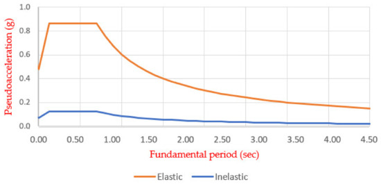
Figure 1.
Elastic and inelastic response spectrum of a house located in the north of Guayaquil.
Method 1 (design based on forces) and method 2 [17] were then applied. Using method 1, the fundamental period of vibration of the structure, which depends on the total height of the building and the coefficients C and α, was calculated, considering a structure with reinforced concrete frames without structural walls, obtaining a period of 0.27 s. With method 2, the fundamental period was obtained using the SAP2000 software, considering the resistant elements’ structural properties and deformation characteristics. It was verified that the value obtained does not exceed the value obtained with method 1 by 30%.
Subsequently, the basal shear resulting from the product of the seismic response coefficient Cs and the reactive seismic load W was determined, which considers the total dead load of the structure. The reactive seismic load considers the total dead load of the structure, and, for this reason, this value will be different for the design of the traditional house and the new alternative. Since the base shear is directly proportional to the seismic load, the one obtained with the structure with non-traditional materials is 32% lower than the structure with conventional materials. In this way, the vertical distribution of individual seismic forces per floor and the basal shear are obtained, resulting in 9.64 tons for option 1 and 7.27 tons for option 2.
As shown below (Table 2), the dead and live loads applied at each level of the structure for both designs are summarized. In additional, a ribbed slab, for which dimensions were obtained in pre-dimensioning, was considered (slab height = 0.2 m; height without compression slab = 0.15 m; compression slab thickness = 0.05 m; nerves width = 0.1 m, and drawer width = 0.4 m).
Table 2.
Loads applied to the structure.
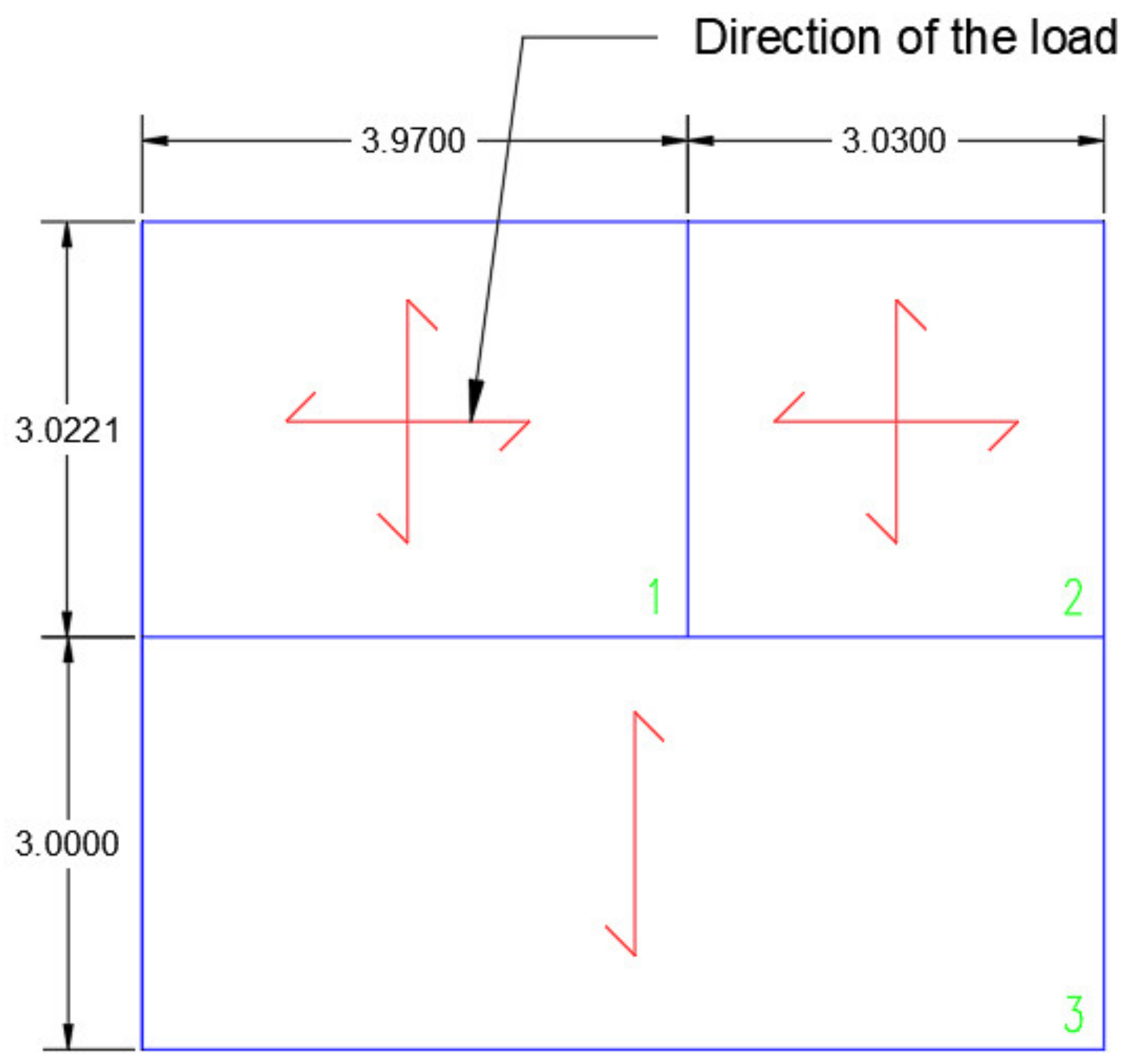
However, one- and two-direction slabs are required in the structural design for both options (Figure 2) due to the relation between the dimensions of the 3 panels that make up the slab between the first and second floor. For the analysis of the slab in two directions, the criterion of the equivalent solid slab was applied from a ribbed slab, by which, through equivalence of properties, an equal thickness for the solid slab of 14.5 cm was obtained to, finally, consider a thickness of 15 cm. In this way, the design of the solid slab was carried out in two directions using the ACI coefficient method [18], which uses tables of coefficients according to the edge conditions and considering the following loads for both floor 1 and the roof and the beam and column dimensions previously determined. Then, it was verified that the initial dimensioning is correct through the requirements of the ACI [18], in which it considers that, when they are monolithic systems, the beams include portions of slabs called wings.

Figure 2.
The direction of the load in the panels of slabs considered (loads in slabs 1 and 2 are both spread out in two directions, but are spread in one direction in slab 3).
To calculate the moments at the straight edges and corresponding to the central strip, the values of the coefficients (defined by abaci) are needed to determine negative moments and positive moments [19], whereas for discontinuous edges, a third of the positive moments are taken. In this way, the steel corresponding to the moment demands was obtained. For the design of the ribbed slab in one direction, the design knowledge of a “T” beam of established width was applied, and the same dimensions of structural elements and loads used for the slab in 2 directions were considered. The moments were calculated for an embedded beam, and in this way, the steel for said demands was obtained. In addition, it was shown that the shear resistance provided by the concrete was greater than the ultimate shear strength given by the demands.
For the pre-dimensioning of the beams (25 × 30 cm for option 1 and 25 × 25 cm for option 2), the one with the largest tributary area was considered as the critical one. The calculation requires the ultimate load, which is obtained from a combination of both dead and live applied loads, and thus obtains the maximum moment to define the dimensions (Figure 3).
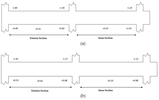
Figure 3.
Maximum moments in beams: (a) option 1, (b) option 2.
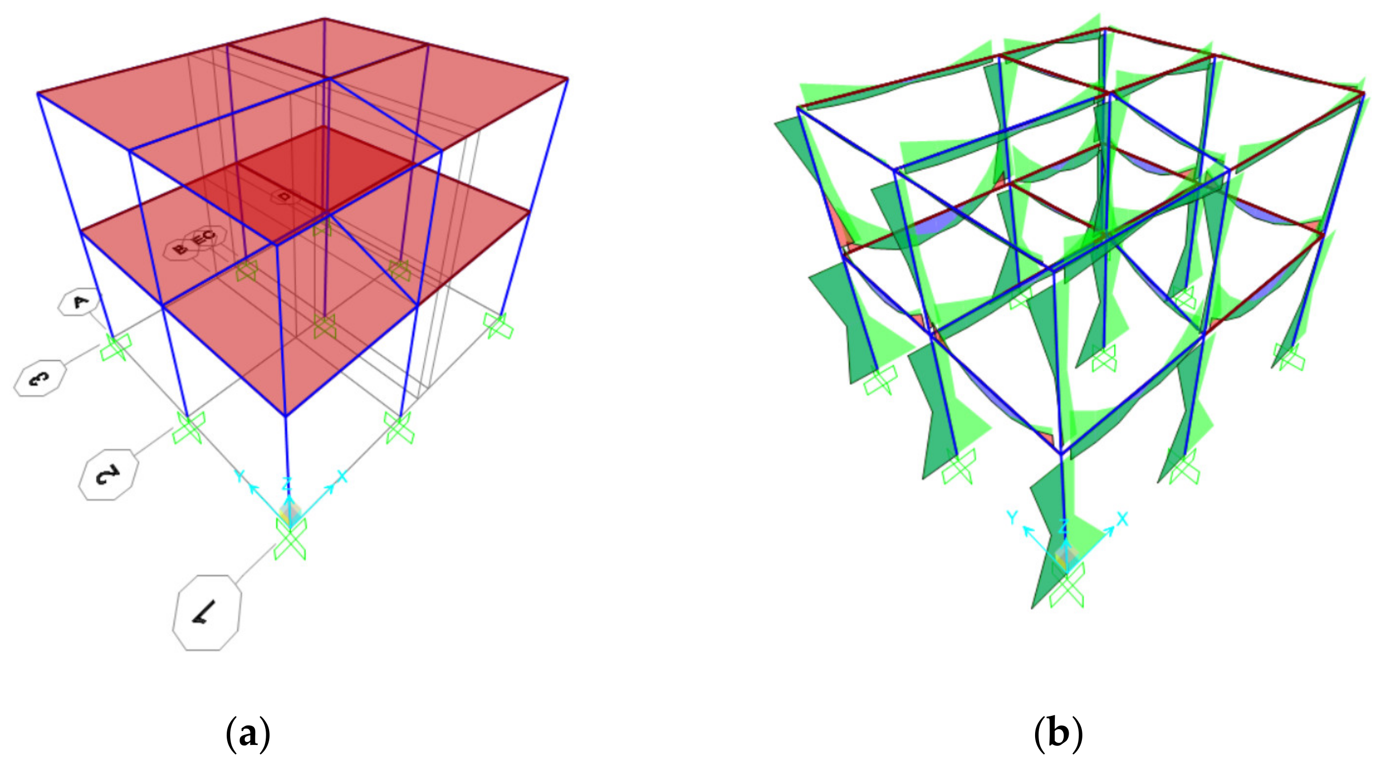
The results of the positive and negative moments of the beams of the two structures were calculated with the formulas presented in the ACI 318-14 code [18] and corroborated with the SAP2000 structural software (Figure 4). It was verified that the positive moment on the face of the joint is greater than or equal to half the negative moment on that same face, that the positive moment in any section of the analyzed element must be greater than or equal to a quarter of the maximum negative moment generated on the faces of the node, and that at least 2 longitudinal bars are required on the lower and upper face of the beam section, in addition to the amount of reinforcement not exceeding 0.025 and being greater than the minimum amount.

Figure 4.
Structural analysis in SAP2000: (a) moment-resistant frame with reinforced concrete elements, (b) moment diagram obtained with load combinations.
Its design is based on fulfilling the requirements presented in Section 18.6: of the ACI 318-14 code “Beams of special moment frames” (the sections’ dimensions were carried out). The required bending reinforcement was determined using the factored moments, mined using the factored moments, and the required anchoring length of the bending reinforcement in the outer column was calculated. It is also mentioned and verified that the transverse reinforcement is placed in a length 2 times the height of the beam to resist the shear, assuming that the shear resistance of the concrete is zero and that the shear resistance of the steel multiplied by a factor of 0.75 is greater than or equal to the design shear, calculated considering the maximum forces generated on the faces of the nodes using the probable flexural strength , as shown below (Equation (1)):
- = area of nonprestressed longitudinal tension reinforcement.
- = specified yield strength for nonprestressed reinforcement.
- = distance from extreme compression fiber to centroid of longitudinal tension reinforcement.
- = depth of equivalent rectangular stress block.
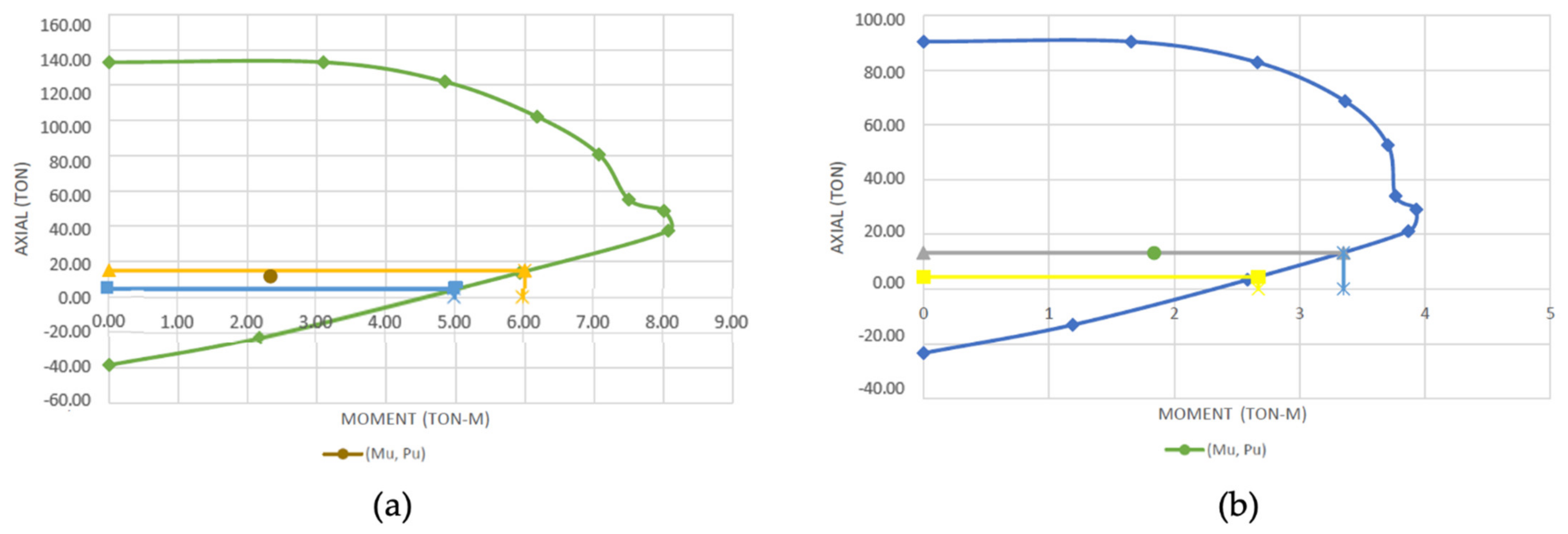
The pre-dimensioning of columns was carried out considering the most critical one, which has the largest area of influence (30 × 30 cm for option 1 and 25 × 25 cm for option 2), considering what is detailed in the NEC-SE-CG code: Loads (Non-Seismic) code [20] for the reduction of live load. The axial loads were obtained from the structural analysis in SAP2000; the required cross-sectional area to support the load was calculated with this value. Its design was based on fulfilling the requirements presented in Section 18.7: “Columns of special moment frames” of the ACI 318-14 code [18]. From the structural analysis, the axial force and design moment for the critical column of the two-story houses were obtained. Initially, a review of the dimensions of the sections was carried out, also considering the provisions of the NEC-SE-VIVIENDA code [21]. Assuming a longitudinal reinforcement of 4 bars of 18 mm for the column of the first option, and 4 bars of 14 mm for the second option (ensuring a permitted amount), the interaction diagrams (Figure 5) were generated where it was verified that the assumed longitudinal reinforcement would be able to withstand the axial force and design moment (Table 3).

Figure 5.
Interaction diagram: (a) option 1, (b) option 2.
Table 3.
Axial force and design moment for columns.
According to the strong column–weak beam criterion, the bending resistance of the columns must comply with the following (Equation (2)): the sum of the nominal bending moments of the columns reaching the node must be greater than or equal to 6/5 of the sum of the nominal bending resistant moments of the beams reaching the node , through a compatibility analysis.
The length for which the reinforcement should be supplied for confinement and its maximum spacing, considering 12-mm stirrups, was determined. Finally, the equation that detailed that the sum of shear strength of concrete and steel multiplied by a reduction factor of 0.75 must be greater than the maximum probable shear resistance is satisfied for both designs.
For the design of the foundations, an isolated square plinth was considered for 3 critical columns, located in the center, edge, and corner. The loads were obtained from the structural analysis carried out in SAP 2000, giving the reactions for a dead load, live load, and an envelope that considers earthquake X and earthquake Y. Columns with dimensions of 30 × 30 cm were considered for the design of a traditional house and 25 × 25-cm columns were considered for the design of a home with a new alternative. The service loads were used for the predimensioning and the design loads, and for the verification of shear, bending, and crushing. To calculate the necessary area, the maximum axial load is multiplied by a factor of safety of 1.5 and divided for the allowable soil load of 10 tons/m2. Once the pre-dimensioning of the plinths had been carried out, the unidirectional shear was calculated considering a critical section located at a distance d from the face of the column. The unidirectional stress that the concrete resists is greater than the ultimate unidirectional stress. Then, the bidirectional shear was calculated considering a critical section located at a distance from the face of the column, in which it was also true that the bidirectional stress that the concrete resists is greater than the ultimate bidirectional stress. In addition, it was verified that the admissible crushing resistance in the footing is greater than the crushing of the column. Finally, for the flexural design, a cut in the face of the column to the extreme fiber was considered to calculate the results that caused the shoe to flex. In this way, the moment results from the product of the resultant by the lever arm. It should be noted that this procedure was performed for each plinth.
2.3. Cycle Analysis
The life cycle analysis is an objective process that allows for an evaluation of the environmental quality of a product or service in a global way, focusing on studying the environmental aspects and potential impacts in the stages of its corresponding life cycle: the acquisition of raw materials, production, use, and final disposal [22]. It is a timely environmental tool to quantify the true impact of the construction of buildings since it is based on objectively studying the different environmental impacts and allows the use of software to evaluate and encompass all the different processes involved, analyzing in-depth the environmental behavior of the inputs (energy, raw materials, and water used) and outputs (general waste and emissions transmitted to the atmosphere) [23].
For the environmental impact assessment, a life cycle analysis (LCA) will be carried out based on the standards ISO 14040 [24] (“Environmental management. Life cycle assessment. Principles and framework”) and ISO 14044 [25] (“Environmental management. Life cycle assessment. Requirements and guidelines”). In addition, it consists of 4 fundamental phases:
- Definition of the Objective and Scope: The objectives were to quantify the environmental impacts associated with the production phase (which includes the supply of raw materials, transport, and manufacturing) and the construction phase (which includes transport and construction/installation processes) of a two-story single-family house with an area of 42 m2 and identify the alternative (masonry with conventional and aerated autoclaved concrete blocks) that contributes to a lesser extent to the impact categories considered. The system’s limits are defined in the EN 15804 standard [26]. The construction of the house comprises processes that consider all the elements, raw materials, and components that comprise it. Therefore, they are affected by the flows of matter and energy during their useful life. For the limits of the system that were considered in this project, two phases can be distinguished (Figure 6): the production phase and the construction phase. The first phase includes the supply of raw materials, transportation, and manufacturing; on the other hand, the construction phase includes transportation and the construction/installation process [27].
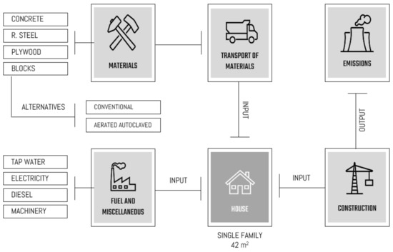 Figure 6. System limits, where the processes considered for the construction of both houses are shown. Made by the authors.
 - Life Cycle Inventory Analysis: Databases provided by Ecoinvent 3.6 (Table 4) were used to establish input and output flows (Table 5), taking as reference the diagram of the system limits (Figure 6). Additionally, the database of a study carried out on the analysis of the life cycle of clinker, cement, and concrete in Ecuador, and of electricity, was used [28] (which includes all types of power plants that are in the country considering the national energy balance of 2018 [29]). The quantities and the transport to the construction site of the materials corresponding to the construction of the gray work of the structure (such as formwork, reinforcing steel, concrete, and blocks) were calculated. Other necessary data were taken from the available inventory, carried out in 2017, of the construction of a hostel located in Lima, Peru. In this analysis, it was assumed that 1.39 kWh/m3 of diesel, 0.30 kWh/m3 of electricity, [30] and 0.5 kL/m2 of water [31] are necessary for the construction of a building. The data was recalculated for a construction area of 42 m2 (Table 5).
Table 4. Summary of processes taken from the Ecoinvent database for the construction of a house (traditional and new alternative).
Table 5. Summary of quantities corresponding to each inflow for the functional unit.
- Life Cycle Impact Assessment: ReCiPe is a method for impact assessment in an LCA. One of the ways to derive characterization factors is at the midpoint level; these indicators focus on single environmental problems [32]. For this study, the ReCiPe Midpoint impact analysis method was used, considering 5 impact indicators among 18: climate change, terrestrial acidification, marine eutrophication, freshwater eutrophication, and photochemical oxidant formation.
- Climate Change—GWP100: Because of climate change, a variety of environmental mechanisms are produced that generate effects on both human health and the health of the ecosystem. The method described above considers the marginal effect of a considerably small amount of CO2 and other greenhouse gases [33]. The reference unit is kg of CO2 equivalent.
- Terrestrial Acidification—TAP100: Substances such as sulfates, nitrates, and phosphates, which persist in the atmosphere, cause a change in the soil’s acidity. A significant deviation from this factor is detrimental to most plant species, as most have an optimal amount of defined acidity. Consequently, due to the variation in acidity levels, changes are generated in the composition of the species. The primary acidifying emissions are NOx, NH3, and SO2 [34]. The unit of measurement is kg SO2 equivalents.
- Freshwater Eutrophication—FEP: Eutrophication is an environmental problem that mainly affects lakes and reservoirs. These are affected due to the variety of activities related to man, such as agriculture and mining, which negatively affect the resource. This phenomenon is caused by the increase in nutrients, usually nitrogen and phosphorus, limiting their use [35]. The unit of measurement is kg of P equivalents.
- Photochemical Oxidant Formation—POFP: Photochemical oxidants are found in photochemical smog (a mixture of primary and secondary atmospheric pollutants), which refer to secondary air pollutants produced by the action of sunlight on nitrogen oxides, reactive hydrocarbons, and their precursors. Ozone and peroxyacetyl nitrate are the main most-relevant phytotoxic components produced by these photochemical reactions [36]. The reference unit is kg NMVOC equivalents.
3. Results and Discussion
3.1. Structural
The structural elements, such as beams, columns, and plinths, had a reduction in their cross-sections. However, slabs and stairs remain with the exact dimensions and steel reinforcement for both designs (Table 6). The most relevant results are presented below:
Table 6.
Reduction percentage in structural elements.
As can be seen, the columns are those with the most significant reduction in cross-sectional area, reaching approximately 31% due to the reduction considered in dimensions of 30 × 30 cm for traditional housing and 25 × 25 cm for non-traditional housing. A similar case occurs with the beams, which had a reduction of approximately 17%, considering sections of 25 × 30 cm for the first option and 25 × 25 cm for the second. In the case of the plinths, a comparison was made between the averages of the cross-sectional areas since three plinths were designed for each housing, with the largest dimensions being B = 1.40 m and B = 1.30 m, respectively.
These results were obtained because the use of lighter materials in the masonry of the second design caused a lower contribution in the dead load of the walls, thus obtaining a total weight of 58.13 tons for this structure and 77.14 tons for the first. Consequently, it was possible to obtain a decrease in the amount of construction materials, such as concrete and reinforcing steel; in this way, the volume of concrete was reduced by 13% and the weight of reinforcement steel by 8%. All these data can be verified in Annex 1, in which the structural plans of both designs are presented.
3.2. Life Cycle Analysis
Table 7 shows the comparison results between the different masonry construction methods in a home. The following images (Figure 7 and Figure 8) quantify the environmental impact of the most significant activities involved in the production and construction phases. According to the indicators, considering the home construction stage, the environmental impact decreases with the newly proposed alternative.
Table 7.
Results of environmental loads for both houses (traditional and non-traditional).
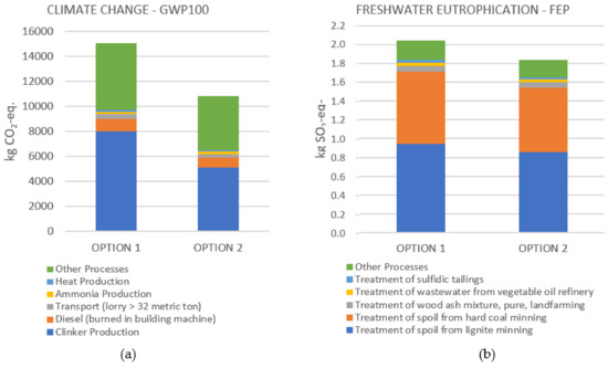
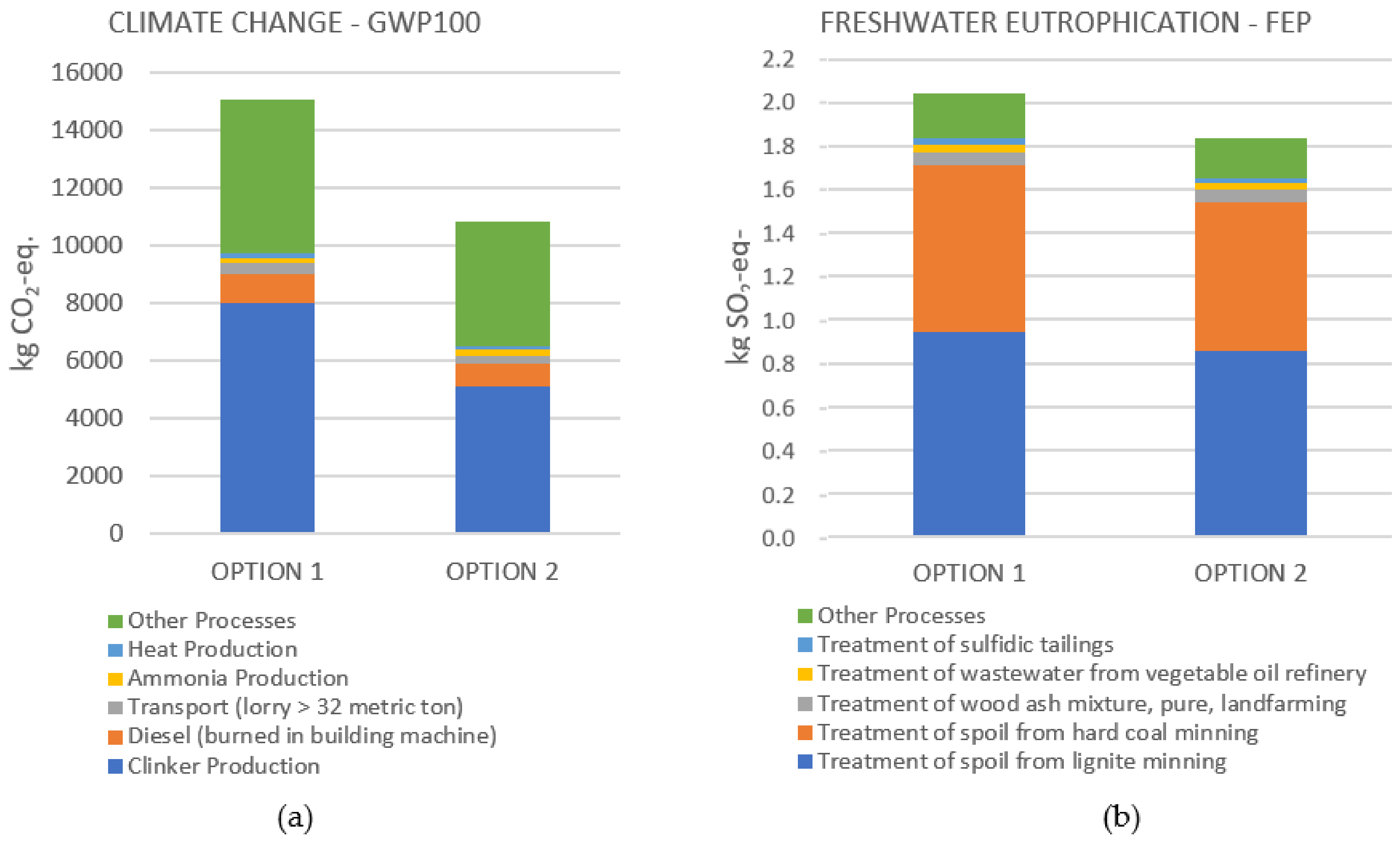
Figure 7.
(a) Processes involved in the environmental impact of the climate change—GWP100 indicator; (b) processes involved in the environmental impact of the freshwater eutrophication—FEP indicator.
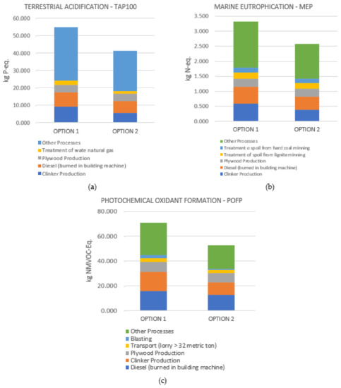
Figure 8.
(a) Processes involved in the environmental impact of the terrestrial acidification—TAP100 indicator; (b) processes involved in the environmental impact of the marine eutrophication—MEP indicator; (c) processes involved in the environmental impact of the photochemical oxidant formation—POFP indicator.
In the climate change indicator—GWP100 (climate change), as shown in Figure 7a, a total of 15,041.87 and 10,824.00 kg CO2-Eq. was obtained for the case of traditional and non-traditional housing, respectively. In comparison, this means a difference of 39% in CO2 emissions. Clinker production turned out to be the process that generated the most significant environmental load, representing a total of 53% (traditional housing) and 47% (non-traditional housing). These results were obtained since, when making cement, clinker production intervenes, contributing to 92% of CO2 emissions and 91% of the energy consumed, according to a study of said system carried out in Ecuador [37]. In this procedure, calcination, the burning of fossil fuels, and electrical energy consumption are considered [38]. On the other hand, another of the processes that generate the emission of CO2, the most prominent component of global warming, is the production of steel, because the furnaces used for its manufacture use temperatures around 1500 °C to carry out their calcination, generating the release of dry dust and greenhouse gases [39].
In the freshwater eutrophication—FEP indicator (Figure 7b), a total of 2.046 and 1.836 kg P-Eq. were obtained for the case of traditional and non-traditional housing, respectively. In this case, a difference of 54% in P (phosphorus) emissions was achieved. The treatment of waste from mining extraction is the process that is highlighted, representing 45% (traditional housing) and 43% (non-traditional housing).
In the terrestrial acidification category—TAP100 (Soil Acidification), as shown in Figure 8a, a total of 54.915 and 35.609 kg SO2-Eq. were obtained for the case of traditional and non-traditional housing, respectively. There is a difference of 54% in SO2 emissions between the construction methods analyzed. The most significant contributor to this impact is the clinker production, representing 17% and 16% of the total impact analyzed. Because the clinker is the main cement component (used in concrete for the construction of structural elements), its production generates high emissions of SO2 to the environment due to the combustion of a considerable amount of fossil fuels, which is quantified in the use of 71.24 kWh to produce 1 ton of clinker [28].
In the indicator marine eutrophication—MEP (acidification of the oceans), Figure 8b, a total of 3.332 and 2.197 kg N-Eq. was obtained for the case of traditional and non-traditional housing, respectively. Thus, a 52% difference in N (nitrogen) emissions resulted. Once again, clinker production is the process that stands out the most, representing a total of 18% (traditional housing) and 14% (non-traditional housing). On the other hand, industrial processes prevail in the generation of emissions of nitrogen oxides (NOx) and phosphorus (P), becoming the main component in the increase of the eutrophication index in the raw material production phase [40].
Results of 70.396 and 52.657 kg NMVOC-Eq. were obtained for the case of traditional and non-traditional housing, respectively, in the photochemical oxidant formation category—POFP (Formation of chemical oxidants), Figure 8c, with a difference of 34% in NMVOC emissions (volatile organic compounds without methane) between both construction methods. The use of fuel (diesel) and clinker production is the predominant activity in this category. Diesel contributes 23% (option 1) and 24% (option 2) in said impact, and clinker production contributes 22% (option 1) and 19% (option 2). To produce 1 ton of clinker, the main component of cement, 0.32 kg of diesel is used, and air emissions of 1.41 kg of nitrogen oxides and 0.077 kg of VOC (Volatile Organic Compounds) are generated [38].
Based on the results of a study conducted by the Residential Building Environmental Sustainability Observatory and the Autonomous University of Madrid [41], promoted by Vía Célere, which is a real estate company dedicated to the development, investment, and management of residential assets, it has been estimated that for each square meter built-in residential buildings, 441 kg CO2-Eq. are generated. According to the above, the functional unit of study, which is a 42-m2 house, should generate 18.522 kg CO2-Eq. This quantity is adjusted to the results obtained from the life cycle analysis for both houses that do not exceed 16.000 kg CO2-Eq.
A study carried out by the Pontificia Universidad Católica del Perú [42] shows that, of the life cycle stages analyzed (pre-use, use and end of life), the pre-use stage of a 130-m2 single-family home of the area with traditional masonry (concrete blocks) is one of the most critical. According to this study, the pre-use stage represents 53.93% of the total (126.624 kg CO2-Eq) in terms of the generation of environmental loads, the use stage represents 43.28%, and finally, the end-of-life stage represents a percentage lower than 2.79%. It should be noted that the pre-use stage considers the phases of manufacturing materials and construction of the house, and that in the calculations, not only the gray work of the structure is considered, but also its finish (plaster, paint, etc.). This shows that the most significant impact is due to industrial processes such as steel and cement production where high temperatures are used, and indicates the areas where efforts could be focused on improving their optimization.
According to the results obtained, the climate change indicator or climate change turned out to be the one that contributes the greatest to the environmental impact because the manufacturing processes necessary for the manufacture of construction materials are those that predominate in the generation of emissions; among these processes are clinker production (cement industry), diesel consumption (cement and wood industry), and transportation (through distribution). A total of 15,000 and 10,000 kg CO2 was obtained for the case of traditional and non-traditional housing, respectively. In comparison, this means a 36% reduction in CO2 emissions.
3.3. Project Budget
The scope of the project budget includes preliminary works, earthworks, foundations, structure, and masonry. These activities will be taken for the budget of the traditional house, and likewise, for the house’s budget with the new alternative. Unit prices were analyzed for each item corresponding to the main activities to estimate the project’s cost. The prices were taken from a database and the INSUCONS portal with verified suppliers.
The wages per hour of labor have been taken from the Table of Minimum Wages of the different occupational categories for construction proposals by the Comptroller General of the State, dated January 2021. The quantities of the materials were obtained for each item established in the budget, taking as reference the structural plans that contain each one of the designs of the foundations and gray work structures of both houses. In addition, a waste percentage was considered, according to the materials.
Finally, for Option 1, a two-story single-family house with conventional concrete block masonry, a total cost of USD 37,232.55 was obtained, corresponding only to gray structure work. In the same way, USD 33,680.33 was obtained for Option 2 (masonry with aerated concrete blocks). This shows that using a lightweight material in masonry can reduce the budget for the construction of a house by approximately 10%. All these data can be verified in Appendix A, in which the budgets for both designs are presented.
3.4. Project Activity Schedule
The calculation of the duration of each activity was determined by the performances established in the unit price analysis. Both houses comprise the same activities, except for the items corresponding to block walls, where there is a variation between the performances. For the construction of walls with conventional concrete blocks, according to the INSUCONS portal, there is a performance of 0.35 h/m2. On the other hand, a performance of 0.09 h/m2 was obtained using aerated concrete blocks, according to tests carried out in the laboratory. As a result, as the approximate time for construction corresponding to gray structure works, for Option 1, a duration of 37 days was obtained, and for Option 2, 33 days.
From the schedule made for both housing projects, there is a total of 14 critical activities: clearing and cleaning, excavation, compacted filling of classified material, layout and stakeout, formwork and formwork of bracing, concrete for plinths, beam formwork and typical formwork (ground floor), concrete for beams (ground floor), formwork and formwork of lightened slabs (upper floor), reinforcing steel for columns (upper floor), concrete for stairs, beam formwork and typical formwork (upper floor), concrete for lightened slab (deck plant), and block masonry (upper floor) (Appendix B).
4. Conclusions
The structural models of the different construction methods comply with the earthquake-resistant design established by the Ecuadorian Construction Standard (NEC 2015) and the minimum design requirements according to ACI 318-14. This indicates that the construction of the house, regardless of the materials used, is feasible, since no limitations were identified that could affect its performance during its useful life; in addition, for both structures, no reinforcement was required (which would translate into an increase in construction costs) to increase stiffness to resist the forces caused by an earthquake.
The use of materials with a density four times lower than the materials usually used in construction is feasible. Aerated concrete blocks represent a new alternative as a constructive method for its application in non-structural elements due to its influence not only on the reduction of the volume of the required materials but also on its easy and fast application, which reduces the time by 17% of project execution.
The use of aerated autoclaved concrete blocks allows the dead load per square meter to be reduced by up to 36% and, in turn, the total weight of the structure by 30% (considering only gray structure work) because of obtaining smaller cross-sectional dimensions of the structural elements. Additionally, it represents a savings of up to 10% in the project’s total cost because of the low demand for materials and the efficiency in the yields of the items analyzed, unlike the traditional construction method.
The application of lighter material in masonry allows for optimizing the quantities of work, minimizing the volume of concrete by up to 13%, 8%, and 73% of the weight of steel and concrete for blocks, respectively. These results demonstrate the benefits of changing the traditional construction method and opening the opportunity to continue evaluating new materials’ characteristics, to encourage sustainable construction in the country.
The life cycle analysis made it possible to identify the processes corresponding to the production and construction phases of the defined functional unit, which contribute considerably to the different categories of environmental impact. The manufacturing processes in the construction industries require mitigation measures or process optimization to avoid the increase in generated emissions. As a result, the construction method with the new alternative reduces the carbon footprint by 36%, establishing itself as a potential option that may be applicable in the future to improve the eco-efficiency of homes and buildings.
5. Recommendations
For the masonry to provide rigidity to the structure without the need to use other reinforcement alternatives, and to ensure the approval of the social environment, there is the option of doubling the density of the cellular concrete blocks and, consequently, increasing the resistance to the compression of these.
For results closer to the Ecuadorian reality, it is recommended carry out the life cycle analysis of the most demanding construction materials using the information on the process mechanism, consumption, emissions, etc., that national industries can offer, to build a more representative database and propose new mitigation measures if necessary.
Take advantage of low-density characteristic of blocks of cellular concrete for its application in other types of construction works, such as groups of houses and buildings, where the benefits would be reflected in a greater magnitude, such as a reduced carbon footprint and cost savings, not only in terms of the volume of material, but also in terms of costs and time.
Completely cover all phases of the life cycle of a home to identify which is the most critical phase, considering other processes that intervene to quantify the consumption of energy or other resources during the occupation stage and final disposition.
Author Contributions
Conceptualization, M.R.-Q., A.R.-T. and N.G.-T.; methodology, M.R.-Q., A.R.-T. and N.G.-T.; validation, M.R.-Q., A.R.-T. and N.G.-T.; formal analysis, M.R.-Q. and A.R.-T.; investigation, M.R.-Q., A.R.-T. and N.G.-T.; resources, M.R.-Q., A.R.-T. and N.G.-T.; writing—original draft preparation, M.R.-Q., A.R.-T. and N.G.-T. writing—review and editing, M.R.-Q., A.R.-T., N.G.-T., H.B. and M.H.C.; visualization, N.G.-T.; supervision, N.G.-T. All authors have read and agreed to the published version of the manuscript.
Funding
This research received no external funding.
Institutional Review Board Statement
Not applicable.
Informed Consent Statement
Not applicable.
Data Availability Statement
The data presented in this study are available on request from the corresponding author.
Acknowledgments
The authors gratefully acknowledge the support provided by Holcim Ecuador S.A. Centro de Innovacion del Hormigon (CIH). The support of Daniel Petroche Sanchez from Holcim Ecuador S.A is gratefully acknowledged.
Conflicts of Interest
The authors declare no conflict of interest.
Appendix A
Plans of both designs: Contains the architectural plan (provided by the client), structural plan of each of the elements (foundations, columns, beams, slabs, and stairs).
Appendix B
Project budget for both designs: Contains a table of items, units, quantities, and final value offered.
References
- García Ochoa, J.; Quito Rodríguez, J.; Perdomo Moreno, J.; Universidad Cooperativa de Colombia. Obtenido de Análisis de la Huella de Carbono en la Construcción y su Impacto Sobre el Ambiente 2020. Available online: https://repository.ucc.edu.co/bitstream/20.500.12494/16031/2/2020_Analisis_huella_carbono.pdf (accessed on 23 May 2021).
- Global Alliance for Buildings and Construction. 2019 Global Status: Report for Buildings and Construction. Available online: https://globalabc.org/sites/default/files/2020-03/GSR2019.pdf (accessed on 28 May 2021).
- Kosmatka, S.; Wilzon, M. Design and Control of Concrete Mixtures: The Guide to Applications, Methods, and Materials; Cement Association: Portland, IL, USA, 2011. [Google Scholar]
- Kibert, C.J. The next generation of sustainable construction. Build. Res. Inf. 2007, 36, 595–601. [Google Scholar] [CrossRef]
- Lucero, K. La Construcción, un Pilar de la Economía Debilitado por la Pandemia. Gestión. 2020. Available online: https://www.revistagestion.ec/economia-y-finanzas-analisis/la-construccion-un-pilar-de-la-economia-debilitado-por-la-pandemia (accessed on 12 May 2021).
- Instituto Nacional de Estadísticas y Censos. Ecuador en Cifras 2016. Available online: https://www.ecuadorencifras.gob.ec/documentos/web-inec/Estadisticas_Economicas/Encuesta_Edificaciones/2016/2016_EDIFICACIONES_PRESENTACION.pdf (accessed on 10 June 2021).
- Instituto Ecuatoriano de Normalización (Ecuadorian Normalization Institute). NTE INEN 2380: Cemento Hidráulico, Requisitos de Desempeño para Cementos Hidráulicos; INEN: Quito, Ecuador, 2011. [Google Scholar]
- Alexander, M.; Mindess, S. Aggregates in Concrete; Taylor & Francis Group: New York, NY, USA, 2005. [Google Scholar]
- Abbès, F.; Abbès, B.; Benkabou, R.; Asroun, A. A FEM Multiscale Homogenization Procedure using Nanoindentation for High Performance Concrete. J. Appl. Comput. Mech. 2020, 6, 493–504. [Google Scholar]
- Benkabou, R.; Abbès, F.; Asroun, A.; Li, Y. Contribution of 3D numerical simulatio of instrumented indentation testing in the identification of elastic-viscoplastic behaviour law of a high-performance concrete. Matériaux Tech. 2017, 105, 102. [Google Scholar] [CrossRef]
- Da Silva, W.E.L.; Němeček, J.; Štemberk, P. Application of multiscale elastic homogenization based on nanoindentation for high performance concrete. Adv. Eng. Softw. 2013, 62, 109–118. [Google Scholar] [CrossRef]
- Santisteban, I.A. Maquinaria y Equipos para la Industria Maderera en Ecuador; ICEX España Exportacion e Inversiones: Quito, Ecuador, 2019. [Google Scholar]
- Cabrera, M.I. Utilización de los Concretos de Alta Resistencia y Concretos Celulares en la Industria de la Construcción Ecuatoriana, Clasificados por Sectores: Vivienda, Electricidad, Gas/Petróleo, Salud y Educación; Revista Digital Universidad Central del Ecuador: Quito, Ecuador, 2015. [Google Scholar]
- Célere, V. Estimación de Huella Hídrica de Una Promoción Residencial; Comunidad ISM: Madrid, Spain, 2019. [Google Scholar]
- Remigio, C.; Abel, S. Análisis de Ciclo de Vida de Una Vivienda Unifamiliar en Huancayo; Pontificia Universidad Catolica del Peru: Lima, Peru, 2016. [Google Scholar]
- Instituto Ecuatoriano de Normalización. NTE INEN 638: Bloques Huecos de Hormigón. Definiciones, Clasificación y Condiciones Generals; INEN: Quito, Ecuador, 2014. [Google Scholar]
- Norma Ecuatoriana de la Construcción. NEC-SE-DS: Peligro Sísmico. Diseño Sismorresistente; NEC: Quito, Ecuador, 2015. [Google Scholar]
- American Concrete Institute. ACI 318-14: Building Code Requirements for Structural Concrete and Commentary; ACI: Indianapolis, IN, USA, 2014. [Google Scholar]
- Ministerio de Desarrollo Urbano y Vivienda. Guía de Práctica para el Diseño de Estructuras de Hormigón Armado de Conformidad con la Norma Ecuatoriana de la Construcción NEC 2015; MIDUVI: Quito, Ecuador, 2016. [Google Scholar]
- Norma Ecuatoriana de la Construcción. NEC-SE-CG: Cargas (No Sísmicas); NEC: Quito, Ecuador, 2015. [Google Scholar]
- Norma Ecuatoriana de la Construcción. NEC-SE-VIVIENDA: Viviendas de Hasta 2 Pisos con Luces de Hasta 5 m; NEC: Quito, Ecuador, 2015. [Google Scholar]
- ISO 14040; Environmental Management—Life Cycle Assessment—Principles and Framwork. International Organization for Standardization: Geneva, Switzerland, 2006.
- Aranda Usón, A.; Zabalza Bribián, I. Ecodiseño y Análisis de Ciclo de Vida; Prensas Universitarias: Zaragoza, Spain, 2010. [Google Scholar]
- Curran, M.A. Life Cycle Assessment Handbook: A Guide for Environmentally Sustainable; Wiley: New Jersey, NJ, USA, 2012. [Google Scholar]
- ISO 14044; Environmental Management—Life Cycle Assessment—Requirements and Guidelines. International Organization for Standardization: Geneva, Switzerland, 2006.
- EN 15804; Sustainability of Construction Works—Environmental Product Declarations—Core Rules for the Product Category of Construction Products. European Standards. British Standards Institute Staff: London, UK, 2012.
- León, K.P. Análsis de Ciclo de Vida de Una Vivienda de Tipo Media en la Ciudad de Guayaquil; Espol: Guayaquil, Ecuador, 2016. [Google Scholar]
- Petroche Sánchez, D. Desempeño Ambiental del Cemento y del Concreto en el Ecuador: Una Puerta a la Construcción Sostenible; Escuela Superior Politecnica del Litoral: Guayaquil, Ecuador, 2020. [Google Scholar]
- Ramirez, A. Life cycle methods to analyze the environmental sustainability of electricity generation in Ecuador: Is decarbonization the right path? Renew. Sustain. Energy Rev. Ecuad. 2020, 134, 110373. [Google Scholar] [CrossRef]
- Zabalza, I.; Scarpellini, S.; Aranda, A.; Llera, E.; Jáñez, A. Use of LCA as a Tool for Building Ecodesign. A Case Study of a Low Energy Building in Spain. Energies 2013, 6, 3901–3921. [Google Scholar] [CrossRef] [Green Version]
- Crawford, R.; Treloar, G. An Assessment of the Energy and Water Embodied in Commercial Building Construction; Australian Life Cycle Assessment Society: Sydney, Australia, 2005. [Google Scholar]
- Huijbregts, M.A.; Steinmann, Z.J.; Elshout, P.M.; Stam, G.; Verones, F.; Vieira, M.; Van Zelm, R. ReCiPe2016: A harmonised life cycle impact assessment method at midpoint and endpoint level. Int. J. Life Cycle Assess. 2017, 22, 138–147. [Google Scholar] [CrossRef]
- Goedkoop, M.; Heijungs, R.; Huijbregts, M.; Schryver, A.D.; Struijs, J.V.Z.R.; Van Zelm, R. ReCiPe 2008: A Life Cycle Impact Assessment Method which Comprises Harmonised Category Indicators at the Midpoint and the Endpoint Level; Ministerie van Volkshuisvesting, Ruimtelijke Ordening en Milieubeheer: The Hague, The Netherlands, 2008.
- Van Zelm, R.; Preiss, P.; Van Goethem, T.; Van Dingenen, R.; Huijbregts, M.A.J. Regionalized life cycle impact assessment of air pollution on the global scale: Damage to human health and vegetation. Atmos. Environ. 2016, 134, 129–137. [Google Scholar] [CrossRef] [Green Version]
- Ledesma, C. Determinación de indicadores de eutrofización en el embalse Río Tercero. Córdoba Argent. Cienc. Agronómica 2013, 44, 419–420. [Google Scholar]
- Guderian, R.D. Effects of Photochemical Oxidants on Plants. Available online: https://cfpub.epa.gov/si/si_public_record_Report.cfm?Lab=NHEERL&dirEntryId=36285 (accessed on 24 May 2002).
- Velez, A.L. Energía contenida y emisiones de CO2 en el proceso de fabricación del cemento en Ecuador. Ambiente Construído 2020, 20, 611–625. [Google Scholar] [CrossRef]
- Hanle, L. Productos industriales y usos del producto: Emisiones de la industria de los minerales. In Directrices del IPCC de 2006 para los Inventarios Nacionales de Gases de Efecto Invernadero; ICAT Initiative for Climate Action Transparency: Geneva, Switzerland, 2006. [Google Scholar]
- Hidalgo, I. Technological prospects and CO2 emission trading analyses in the iron and steel industry: A global model. Energy 2005, 30, 583–610. [Google Scholar] [CrossRef]
- Guerra Jesús, B.N. Análisis de Ciclo de Vida de Una Vivienda Unifamiliar de Bambu; Pontificia Universidad Catolica del Peru: Lima, Peru, 2021. [Google Scholar]
- Solis Guzman, J. Metodología para determinar la huella ecológica de la construcción de edificios de uso residencial en España. In Proceedings of the Actas del I Congreso Internacional de Construcción Sostenible y Soluciones Eco-Eficientes, Sevilla, Spain, 20–22 May 2013. [Google Scholar]
- Ramos Espinoza, D.S. Análisis de Ciclo de Vida de Una Vivienda Unifamiliar en Cusco; Pontificia Universidad Catolica del Peru: Lima, Peru, 2018. [Google Scholar]


Publisher’s Note: MDPI stays neutral with regard to jurisdictional claims in published maps and institutional affiliations. |
© 2022 by the authors. Licensee MDPI, Basel, Switzerland. This article is an open access article distributed under the terms and conditions of the Creative Commons Attribution (CC BY) license (https://creativecommons.org/licenses/by/4.0/).