
Structural Optimization of Vented Brake Rotors with a Fully Parameterized Model


Abstract
:1. Introduction
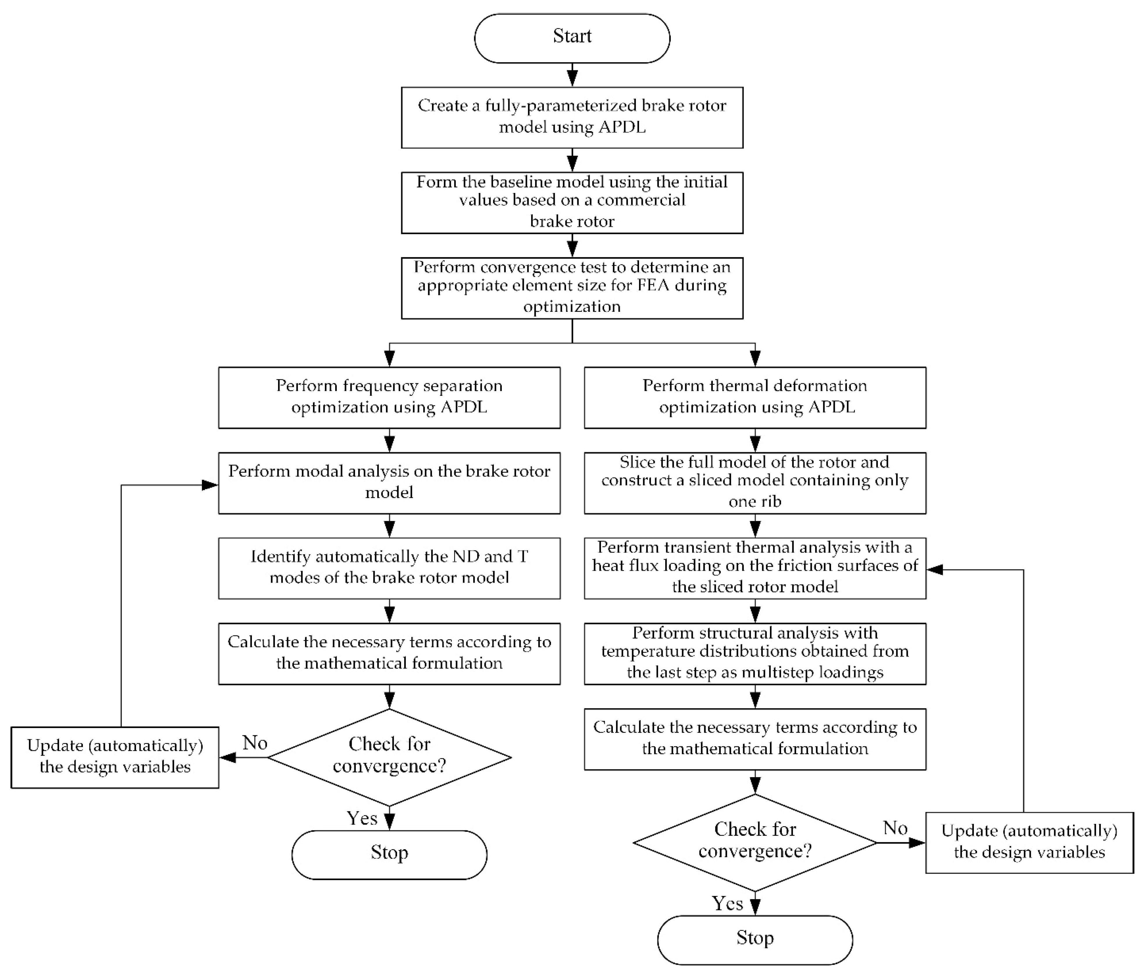
2. Research Methods
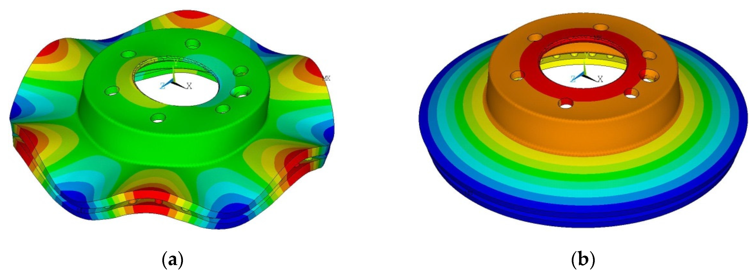
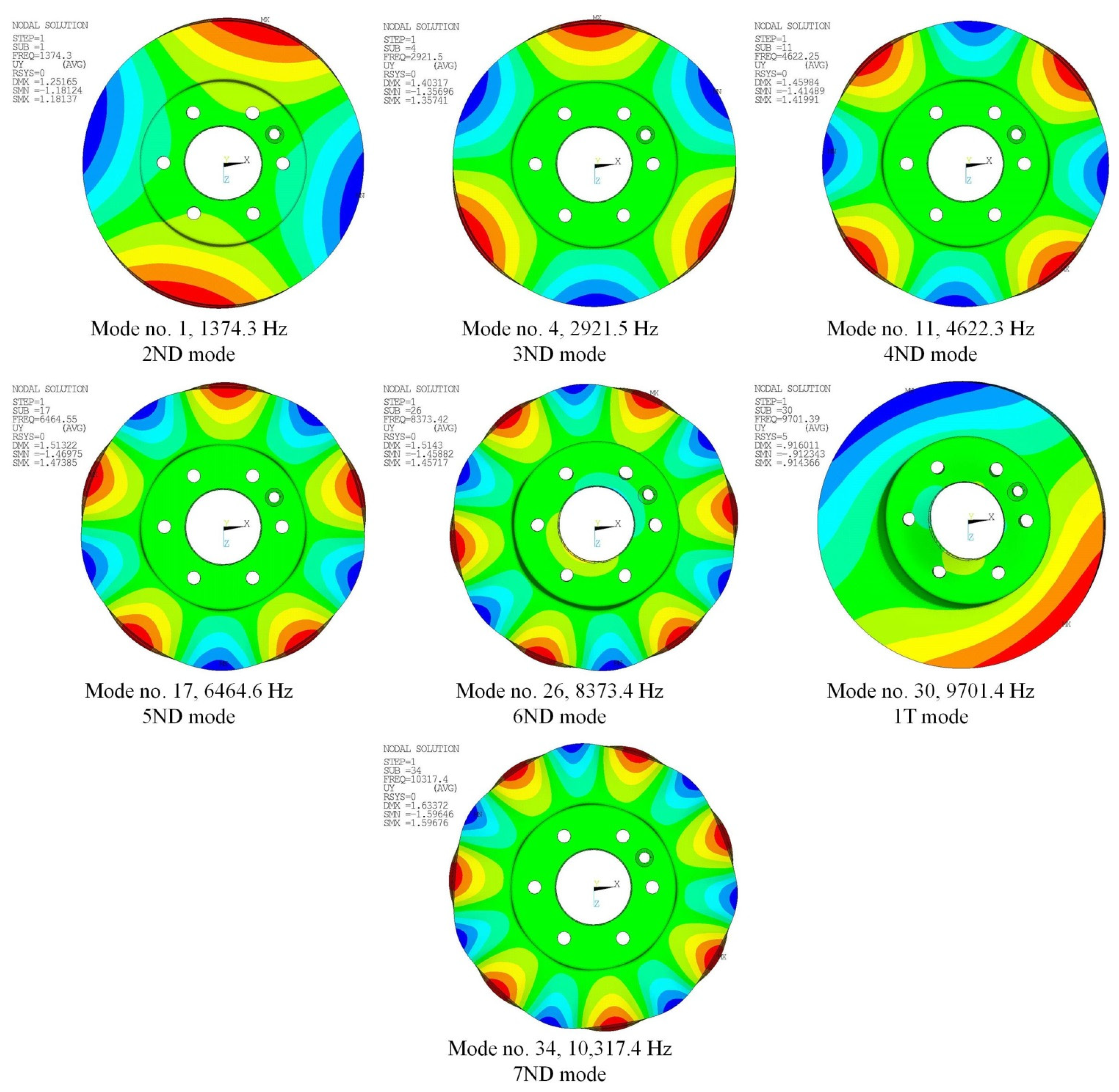
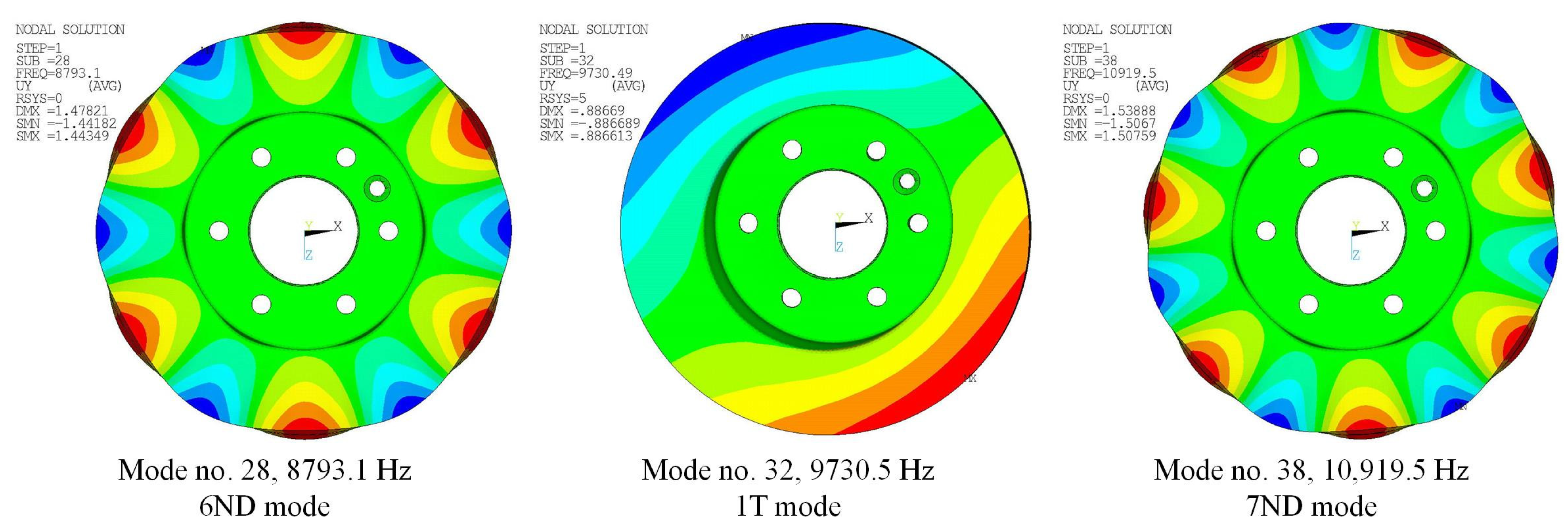
2.1. Brake Rotor Modes Description
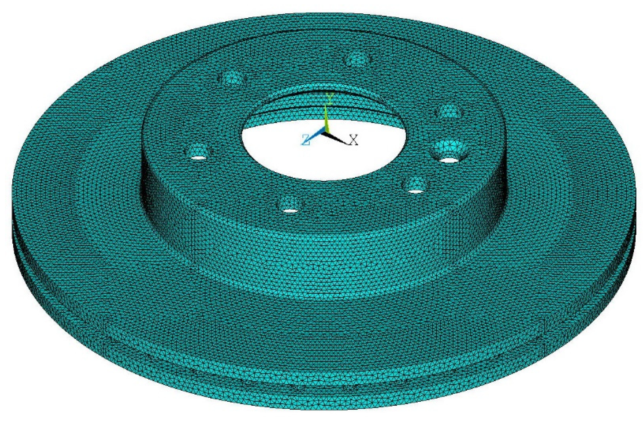
2.2. The Fully Parameterized Brake Rotor Model
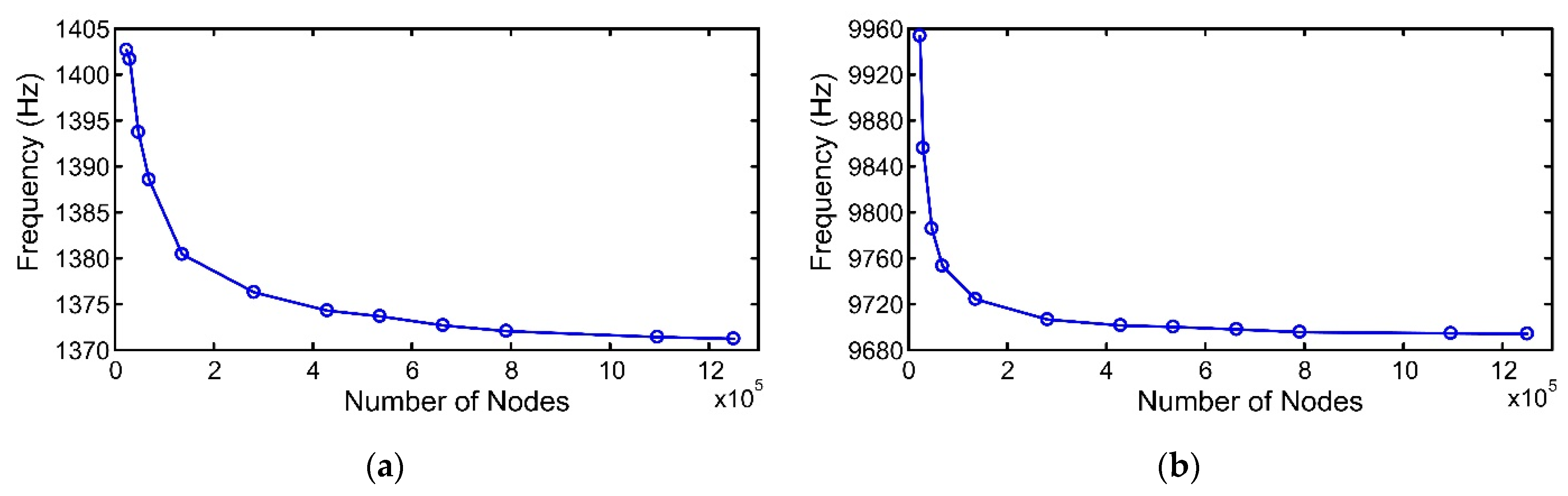
2.3. Convergence Test
2.4. Automatic Identification of the ND and T Modes
- During modeling, 360 hardpoints evenly distributed on the rim of the top surface of the rotor disc were first defined, and the finite element nodes at these hardpoints (defined as the key nodes) were extracted and renumbered sequentially;
- Modal analysis was performed to solve for 40 flexural modes;
- The Cartesian coordinate system was selected;
- The largest amplitude in the y-direction among all finite element nodes of each mode was identified, by which all nodal y displacements of the key nodes within the same mode were divided (normalization);
- Starting from the first mode (the lowest frequency), modes with normalized y displacements at the key nodes equal or very close to +1/−1 were identified, alternating behavior of positive and negative displacements at the key nodes was checked, and the numbers of alternating regions and the key nodes in each region were counted;
- Consecutively, 2ND through 7ND modes were identified;
- The cylindrical coordinate system was selected;
- Excluding the identified ND modes, the above procedure was repeated, with θ direction replacing the y-direction, and the 1T and 2T modes were identified, if necessary.
3. Results and Discussion
3.1. Case 1: Frequency Separation Optimization
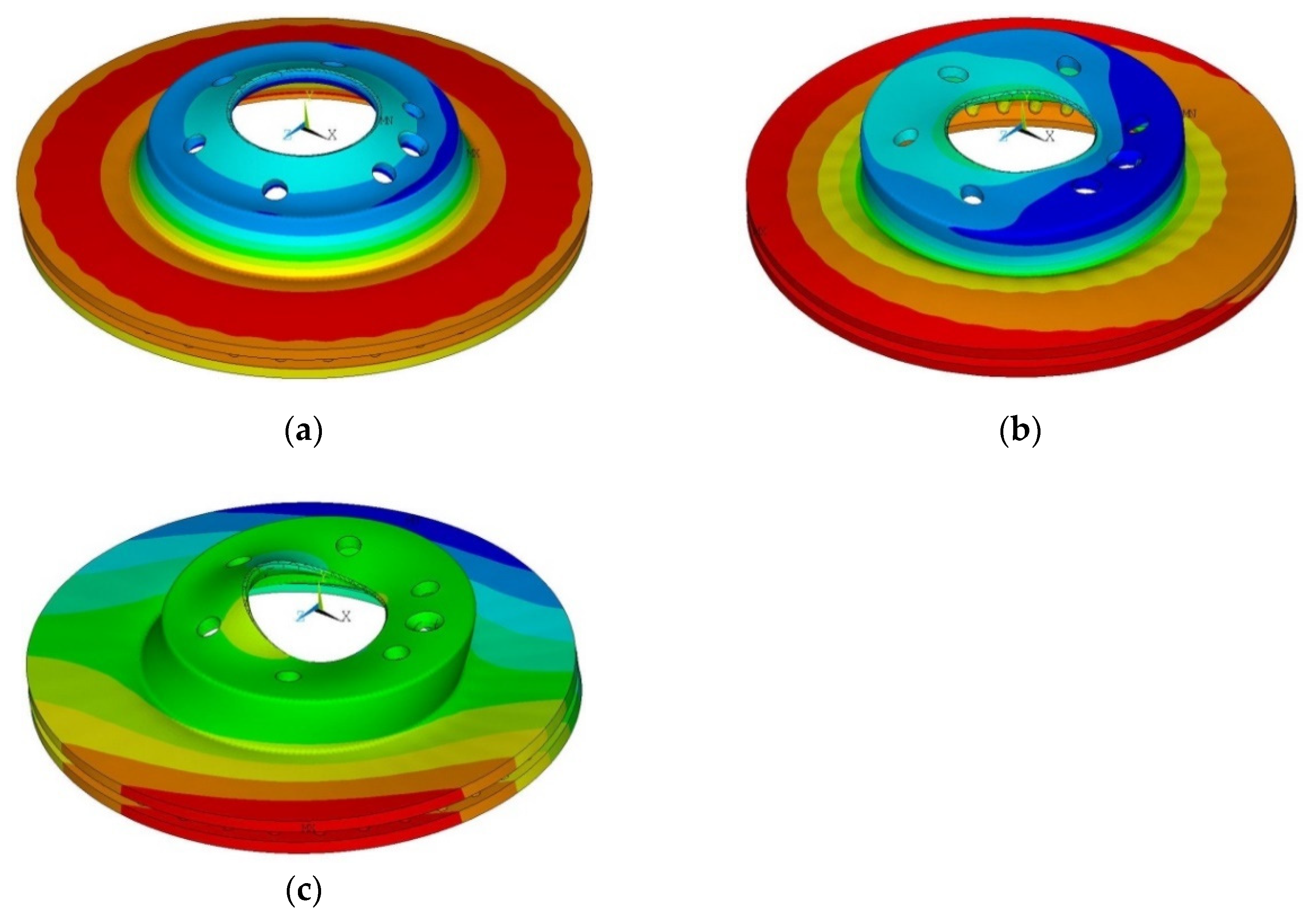
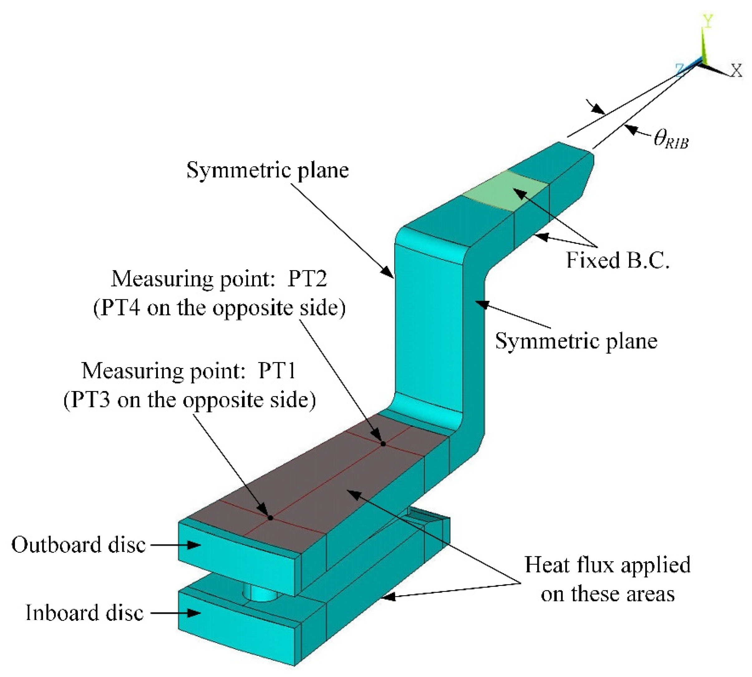
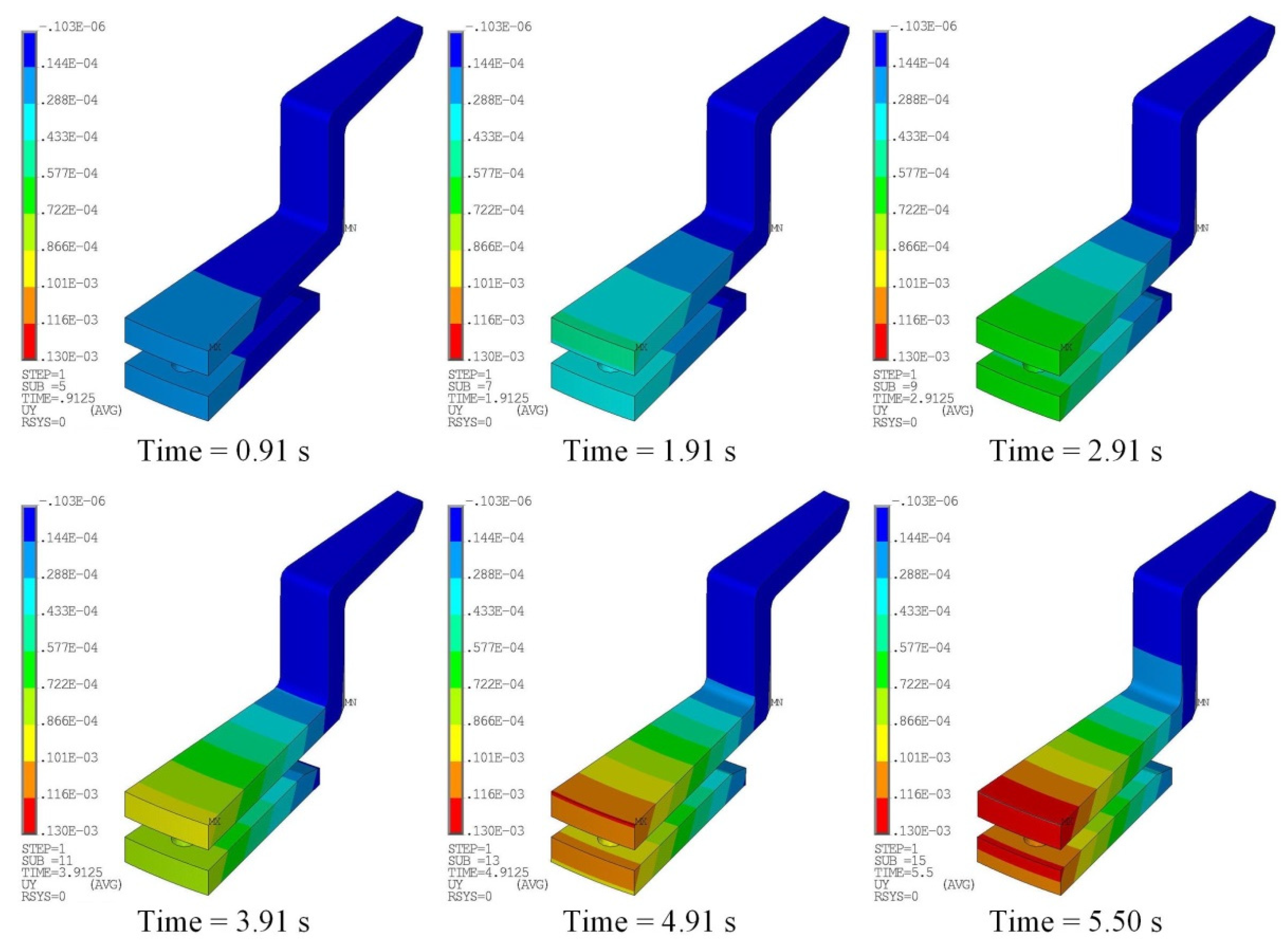
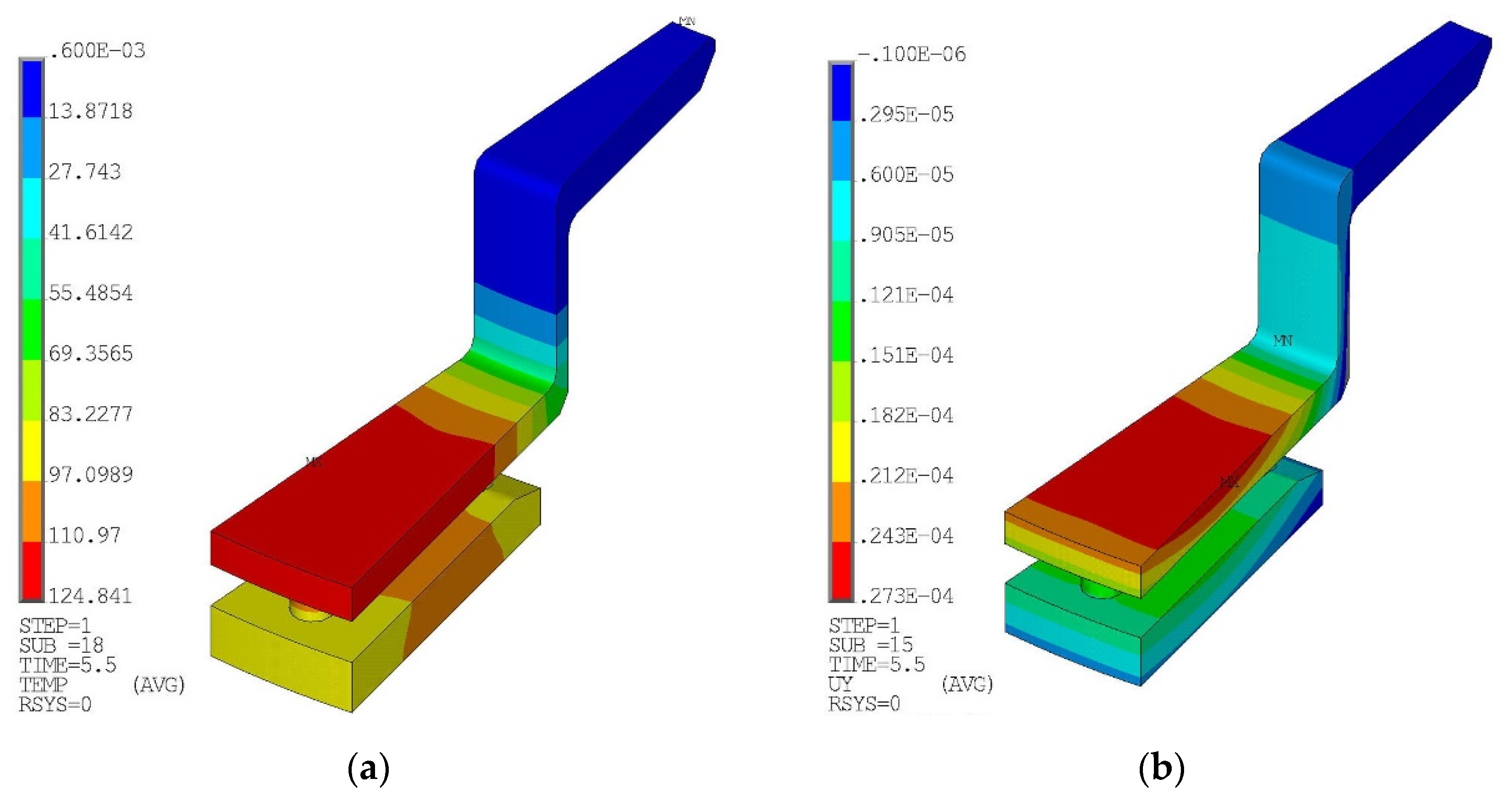
3.2. Case 2: Thermal Deformation Optimization
- A complete solid model of the brake rotor was first created using the parameterized model;
- The complete model was sliced through while avoiding the holes on top of the hub, to construct a sliced model containing only one rib;
- A transient thermal analysis was performed with a heat flux loading applied on the friction surfaces of the sliced rotor model;
- A series of temperature distributions as functions of time on the model were obtained;
- Then, with the temperature distributions as multistep loadings, a structural analysis was executed to acquire the thermal deformation of the model;
- Uy1 through Uy4 were extracted at four measurement points, and the brake rotor coning was calculated.
4. Conclusions
- Structural optimization, including frequency separation maximization and thermal distortion minimization, based on a fully parameterized model for vented brake rotors can be efficient and very effective;
- During an optimization process involving modal analysis, mode orders alter as the geometry changes. Therefore, it is of the utmost importance that the code be able to automatically identify and track correct modes, and consequently, that the modal frequencies not be misused for calculating constraints or the objective function;
- Abrupt temperature variation near the intersection of the hub and disc caused brake rotor coning. However, uneven temperature distribution between the inboard and outboard discs could offset the coning effects to some extent. A brake rotor design with a thinner outboard disc and a thicker inboard disc provides a great choice for rotor coning reduction.
Author Contributions
Funding
Institutional Review Board Statement
Informed Consent Statement
Data Availability Statement
Conflicts of Interest
References
- Abu-Bakar, A.R.; Ouyang, H.; Khai, L.C. Thermal analysis of a disc brake model considering a real brake pad surface and wear. Int. J. Veh. Struct. Syst. 2010, 2, 20–27. [Google Scholar] [CrossRef] [Green Version]
- Belhocine, A.; Bouchetara, M. Thermomechanical behaviour of dry contacts in disc brake rotor with a grey cast iron composition. Trans. Indian Inst. Met. 2012, 65, 231–238. [Google Scholar] [CrossRef]
- Belhocine, A.; Bouchetara, M. Thermo-mechanical coupled analysis of automotive brake disc. Int. J. Precis. Eng. Manuf. 2013, 14, 1591–1600. [Google Scholar] [CrossRef]
- Kim, S.M. A study on thermal analysis in ventilated brake by FEM. J. Korean Soc. Mach. Tool Engr. 2009, 18, 544–549. [Google Scholar]
- Jung, S.P.; Park, T.W.; Chai, J.B.; Chung, W.S. Thermo-mechanical finite element analysis of hot judder phenomenon of a ventilated disc brake system. Int. J. Precis. Eng. Manuf. 2011, 12, 821–828. [Google Scholar] [CrossRef]
- Jung, S.P.; Kim, Y.G.; Park, T.W. A Study on thermal characteristic analysis and shape optimization of a ventilated disc. Int. J. Precis. Eng. Manuf. 2012, 13, 57–63. [Google Scholar] [CrossRef]
- Thilak, V.M.M.; Krishnaraj, R.; Sakthivel, M.; Kanthavel, K.; Deepan Marudachalam, M.G.; Palani, R. Transient thermal and structural analysis of the rotor disc of disc brake. Int. J. Sci. Eng. Res. 2011, 2, 1–4. [Google Scholar]
- Güleryüz, I.C.; Karadeniz, Z.H. Transient thermal analyses of an integrated brake rotor and wheel hub for heavy duty vehicles. Proc. Inst. Mech. Eng. Part D J. Auto Eng. 2021. [Google Scholar] [CrossRef]
- Zhang, S.; Yin, J.; Liu, Y.; Liu, N.; Sha, Z.; Wang, Y.; Rolfe, B. Thermal–structural coupling analysis of brake friction pair based on the displacement gradient circulation method. Adv. Mech. Eng. 2018, 10, 1–13. [Google Scholar] [CrossRef] [Green Version]
- Papinniemi, A.; Lai, J.C.S.; Zhao, J.; Loader, L. Brake squeal: A literature review. Appl. Acoust. 2002, 63, 391–400. [Google Scholar] [CrossRef]
- Chen, F.; Mckillip, D.; Luo, J.; Wu, S. Measurement and analysis of rotor in-plane mode induced disc brake squeal and beyond. SAE Pap. 2004, 2004-01-2798. [Google Scholar] [CrossRef]
- Karamoozian, A.; Tan, C.A.; Wang, L. Squeal analysis of thin-walled lattice brake disc structure. Mater. Des. 2018, 149, 1–14. [Google Scholar] [CrossRef]
- Cha, B.; Jung, T.; Hong, Y.; Park, S. Design optimization of disc brake for reducing squeal noise by frequency sensitivity analysis. Int. J. Eng. Technol. 2018, 10, 263–268. [Google Scholar] [CrossRef] [Green Version]
- Papinniemi, A.; Zhao, J.; Stanef, D.; Ding, J. An investigation of in-plane vibration modes in disc brake squeal noise. SAE Pap. 2005, 2005-01-3923. [Google Scholar] [CrossRef]
- Bae, J.C.; Wickert, J.A. Free vibration of coupled disk-hat structures. J. Sound Vib. 2000, 235, 117–132. [Google Scholar] [CrossRef]
- Hassan, M.Z.; Brooks, P.C.; Barton, D.C. A predictive tool to evaluate disk brake squeal using a fully coupled thermomechanical finite element model. Int. J. Veh. Des. 2009, 51, 124–142. [Google Scholar] [CrossRef]
- Ouyang, H.; Abu-Bakar, A.R.; Li, L. A combined analysis of heat conduction, contact pressure and transient vibration of a disc brake. Int. J. Veh. Des. 2009, 51, 190–206. [Google Scholar] [CrossRef]
- Nouby, M.; Srinivasan, K. Simulation of the structural modifications of a disc brake system to reduce brake squeal. Proc. Inst. Mech. Eng. Part D J. Auto Eng. 2011, 225, 653–672. [Google Scholar] [CrossRef]
- Hassan, M.Z.; Brooks, P.C.; Barton, D.C. The evaluation of disc brake squeal propensity through a fully coupled transient thermomechanical model. Proc. Inst. Mech. Eng. Part D J. Auto Eng. 2013, 227, 361–375. [Google Scholar] [CrossRef]
- SAE International. Disc and Drum Brake Dynamometer Squeal Matrix; SAE J2521:2003; SAE International: Warrendale, PA, USA, 2003. [Google Scholar] [CrossRef]
- Gao, P.; Du, Y.; Walker, P.D. Vibration energy and repeated-root modes of disc rotor for high- frequency brake squeal. Proc. Inst. Mech. Eng. Part K J. Multi-Body Dyn. 2019, 233, 363–378. [Google Scholar] [CrossRef]
- Galindo-Lopez, C.H.; Tirovic, M. Maximising heat dissipation from ventilated wheel-hub-mounted railway brake discs. Proc. Inst. Mech. Eng. Part F J. Rail Rapid Transit 2013, 227, 269–285. [Google Scholar] [CrossRef]
- Roy, I.; Bharatish, A. Optimization of ventilated brake disc rotor geometry for enhanced structural characteristics. J. Meas. Eng. 2020, 8, 98–106. [Google Scholar] [CrossRef]
- Topouris, S.; Tirovic, M. Design synthesis and structural optimization of a lightweight, monobloc cast iron brake disc with fingered hub. Eng. Optim. 2019, 51, 1710–1726. [Google Scholar] [CrossRef]
- Park, S.; Lee, K.; Kim, S.; Kim, J. Brake-disc holes and slit shape design to improve heat dissipation performance and structural stability. Appl. Sci. 2022, 12, 1171. [Google Scholar] [CrossRef]
- Leissa, A.W. Vibration of Plates; Scientific and Technical Information Division, National Aeronautics and Space Administration: Hampton, VA, USA, 1969. [Google Scholar]
- Ferreto, C.J.; Carvalho, A.; Abreu, R.D.A.; Marinho, P.; Guimarães, L. Variation of rotor natural frequencies due to manufacturing and its influence on disc brake noise generation. SAE Pap. 2017, 2017-36-0006. [Google Scholar] [CrossRef]
- ANSYS, Inc. ANSYS Advanced Analysis Techniques Guide; ANSYS, Inc.: Canonsburg, PA, USA, 2005. [Google Scholar]
- Lee, S.; Yeo, T. Temperature and coning analysis of brake rotor using an axisymmetric finite element technique. In Proceedings of the 4th Korea-Russia International Symposium on Science and Technology, Ulsan, Korea, 27 June–1 July 2000; pp. 17–22. [Google Scholar] [CrossRef]
- Okamura, T.; Yumoto, H. Fundamental study on thermal behavior of brake discs. SAE Pap. 2006, 2006-01-3203. [Google Scholar] [CrossRef]


| DCEN | DI1 | DI2 | DI3 | DO1 | DO2 | DO3 | R1 | R2 | R3 | SCH1 |
|---|---|---|---|---|---|---|---|---|---|---|
| 61 | 123 | 142.6 | 147.6 | 135 | 230.6 | 222.6 | 2 | 2 | 2 | 1 |
| SCH2 | SCH3 | SCHX | SCHY | TC | TF1 | TF2 | TRIB | WRIB | Y1 | θRIB |
| 3.5 | 2 | 6 | 2 | 6 | 6 | 6 | 5 | 5.4 | 27.5 | 10° |
| Young’s Modulus (GPa) | Poison’s Ratio | Density (kg/m3) | Thermal Exp. Coef. (1/°C) | Thermal Conduct. (W/(m°C)) | Specific Heat (J/(kg°C)) |
|---|---|---|---|---|---|
| 128.75 | 0.28 | 7220 | 1.1 × 10⁻⁵ | 55 | 500 |
| Element Size (mm) | No. of Nodes | Max. Relative Error |
|---|---|---|
| 10 | 23,953 | 5.49% (35th mode) |
| 8 | 30,170 | 5.40% (35th mode) |
| 6 | 47,723 | 4.45% (35th mode) |
| 5 | 69,025 | 3.89% (35th mode) |
| 4 | 135,872 | 1.94% (35th mode) |
| 3 | 281,539 | 1.02% (35th mode) |
| 2.5 | 429,193 | 0.57% (35th mode) |
| 2.2 | 535,311 | 0.44% (35th mode) |
| 2.1 | 662,995 | 0.33% (35th mode) |
| 2 | 790,894 | 0.19% (35th mode) |
| 1.8 | 1,096,105 | 0.04% (8th mode) |
| 1.7 | 1,250,497 | - |
| DVs and Conditions | Baseline Model | Optimized Model |
|---|---|---|
| DV: DI1 (mm) | 123.00 | 126.90 |
| DV: TF1 (mm) | 6.00 | 6.58 |
| DV: TF2 (mm) | 6.00 | 7.11 |
| DV: TRIB (mm) | 5.00 | 4.05 |
| fsep1, 1T and 6ND (Hz) | 1328.0 | 936.1 |
| fsep2, 7ND and 1T (Hz) | 616.0 | 1189.3 |
| fobj (Hz) | 1944.0 | 2125.4 |
| Mass of the model (kg) | 3.507 | 3.525 (+0.51%) |
| DVs and Conditions | Baseline Model | Optimized Model |
|---|---|---|
| DV: DI1 (mm) | 123.00 | 127.68 |
| DV: TF1 (mm) | 6.00 | 4.81 |
| DV: TF2 (mm) | 6.00 | 7.20 |
| DV: TRIB (mm) | 5.00 | 5.86 |
| Uy1 (mm) | 0.1122 | 0.0257 |
| Uy2 (mm) | 0.0481 | 0.0211 |
| Uy3 (mm) | 0.0924 | 0.0054 |
| Uy4 (mm) | 0.0344 | 0.0027 |
| Uy1 − Uy2 (mm) | 0.0641 | 0.0046 |
| Uy3 − Uy4 (mm) | 0.0580 | 0.0027 |
| Objective function (mm) | 0.0611 | 0.0037 |
| Mass, complete model (kg) | 3.507 | 3.264 (−6.9%) |
Publisher’s Note: MDPI stays neutral with regard to jurisdictional claims in published maps and institutional affiliations. |
© 2022 by the authors. Licensee MDPI, Basel, Switzerland. This article is an open access article distributed under the terms and conditions of the Creative Commons Attribution (CC BY) license (https://creativecommons.org/licenses/by/4.0/).
Share and Cite
Huang, Y.-T.; Liu, Y.-C.; Chen, K.-N.; Lai, Y.-M. Structural Optimization of Vented Brake Rotors with a Fully Parameterized Model. Appl. Sci. 2022, 12, 2184. https://doi.org/10.3390/app12042184
Huang Y-T, Liu Y-C, Chen K-N, Lai Y-M. Structural Optimization of Vented Brake Rotors with a Fully Parameterized Model. Applied Sciences. 2022; 12(4):2184. https://doi.org/10.3390/app12042184
Chicago/Turabian StyleHuang, Yao-Tien, Ying-Chieh Liu, Kun-Nan Chen, and Yueh-Mei Lai. 2022. "Structural Optimization of Vented Brake Rotors with a Fully Parameterized Model" Applied Sciences 12, no. 4: 2184. https://doi.org/10.3390/app12042184