Article

A MIMO Antenna with High Gain and Enhanced Isolation for WLAN Applications

1
College of Electrical and Electronics Engineering, Wenzhou University, Wenzhou 325035, China
2
National Physical Laboratory, Teddington, Middlesex TW11 0LW, UK
*
Authors to whom correspondence should be addressed.
Appl. Sci. 2022, 12(5), 2279; https://doi.org/10.3390/app12052279
Submission received: 21 December 2021 / Revised: 18 February 2022 / Accepted: 21 February 2022 / Published: 22 February 2022

Abstract

:
In this paper, a novel two-port dual-band multiple-input-multiple-output (MIMO) antenna with enhanced isolation and high gain is presented. The presented antenna is composed of a symmetrical ground element and two identical antenna radiating elements. At the bottom of the substrate, the ground part is applied to strengthen the isolation performance of the designed MIMO antenna. The measured −10 dB bandwidth according to the input reflection coefficient S11 are 650 MHz (2.25–2.9 GHz) and 980 MHz (5.05–6.03 GHz), which are in strong agreement with the 2.4 GHz frequency band (2.4–2.4835 GHz) and the 5 GHz frequency band (5.15–5.85 GHz) of wireless local area network (WLAN) applications. The measured S21 at both the lower and the higher frequency operation bands are less than −19.3 dB. In the operating frequency bands, the measured gain is from 1.5 dBi to 3.8 dBi. The measured results show that the presented MIMO antenna is a good candidate for WLAN applications.

1. Introduction

With the widespread applications of wireless communication technologies, an ever-increasing amount of data is flooded with wireless transmissions. The WLAN frequency band commonly used in wireless communications is already overcrowded. To achieve a larger channel capacity, multiple-input-multiple-output is a well-known solution [1,2]. When MIMO antennas are applied at the transmitting and receiving ends, mutual interference occurs between the antenna elements [3]. In order to work efficiently, the antenna elements must be isolated from each other [4]. Therefore, it is extremely important to reduce mutual coupling between the antenna elements in MIMO antenna design. Additionally, for the sake of portability and to keep costs down, many efforts must be made to minimize the dimension of MIMO antenna.
In MIMO antenna systems, a common approach is to isolate the two elements by increasing the distance between them. However, this will inevitably lead to a large occupied area. Within the occupied area, many methods to minimize mutual coupling have been proposed, such as the employment of band gap structures [5], decoupling networks [6,7], neutralization lines [8], defected ground structures [9] and parasitic elements [10]. These technologies reduce the coupling by minimizing, attenuating and blocking the surface currents [11].
In this paper, a compact high-gain and enhanced-isolation MIMO antenna printed on an FR4 substrate is presented for IEEE 802.11 a/b/g/n/p/ac/ax (2.4–2.4835 GHz and 5.15–5.85 GHz) applications. The radiating array consists of two miniaturized antenna elements with neutralization lines and defected structure on the ground plane. The radiating antenna element includes an inverted L-shaped short strip, a stepped strip and a rectangular microstrip feeding structure. This paper discusses and analyzes the reflection coefficients, peak gain, surface current distribution and radiation efficiency of the designed MIMO antenna. The dimension of the presented dual-port MIMO antenna is approximately 50 mm × 50 mm × 1.6 mm.

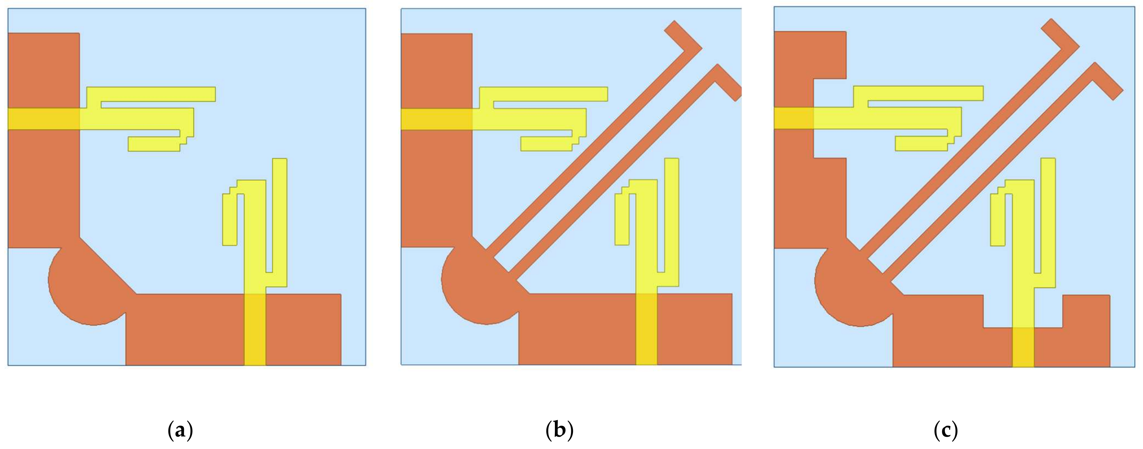
2. Antenna Structure and Design

Figure 1 illustrates three steps of the presented antenna design process. Antenna 1 investigated the optimization of the position and size of the two antenna elements according to the reflection coefficients. As shown in Figure 2a, the frequency bands of antenna 1 are approximately 1 GHz (2.7–3.7 GHz) and 1.7 GHz (6.9–8.6 GHz). The resonance points are 3.24 GHz and 7.6 GHz, respectively.
Compared with antenna 1, antenna 2 has two inverted L-shaped stubs on the ground plane. As shown in Figure 2b, the S21 parameter values of antenna 2 in the 5–7 GHz frequency band are almost 10 dB smaller than those of antenna 1. It can be seen that the L-shaped stubs greatly enhance the isolation performance at both operating frequency bands. The inverted L-shaped stubs play a role in the neutralizing line. The neutralization line structure guides the radiation field to gather along the diagonal direction of the neutralization line instead of cross-coupling effects.
Antenna 3 is the proposed antenna of this paper. A small rectangular was cut out of the ground plane to reduce the S11 values of antenna elements in the 2–3 GHz frequency band, and the resonance point of higher frequency band was shifted to the lower frequencies. It makes the radiation field of the operating frequency band concentrated on the two elements of antenna. In Figure 2a, the −10 dB operating frequency bands of the presented antenna are 2.16–3.05 GHz and 4.92–6.45 GHz.
The top and bottom layers of the presented antenna are shown in Figure 3. It is fabricated on an FR4 substrate with a substrate height of 1.6 mm, loss tanδ of 0.02 and a relative permittivity εr of 4.4. Two radiating antenna elements are located on the top layer of the substrate. Each element includes an L-shaped short strip, a stepped folding strip and a rectangular feeding microstrip. The ground part is located on the bottom of the substrate. It is employed to improve the isolation of two elements. It is spliced together by two recessed metal elements, a semicircular strip and two opposite inverted-L-shaped strips. The two radiating antenna elements and ground plane are both symmetrical along the diagonal of the substrate.
To optimize the dimension of the proposed antenna, different values of L1 and W9 have been investigated. As shown in Figure 4a, when the value of L1 is 1.5, 2 and 2.5 mm, the higher operating frequency band of the antenna only changes a little, but the lower frequency band changes a lot. Therefore, we can optimize the value of L1 to tune the lower operating frequency band. As shown in Figure 4b, the higher frequency band changes significantly when the value of W9 is changed. Therefore, we can optimize the value of W9 to tune the higher operating frequency band. Therefore, the operating frequency bands are 2.16–3.05 GHz and 4.92–6.45 GHz when the values of L1 and W9 are 2 mm and 4.5 mm, respectively. The final values of presented antenna dimensions are listed in Table 1.
The designed antenna is based on linear polarization theory. The two ports adopt the same excitation mode. Figure 5 shows the current distribution of the proposed MIMO antenna when two ports are excited. At the frequency of 2.45 GHz, the main currents are focused on the stepped folding strip, the rectangular feeding microstrip and part of the inverted L-shaped strips on the ground plane. Therefore, the current intensity around the radius of R is small. At the frequency of 5.5 GHz, the main currents are focused on the corner of the stepped folding strips and both inverted L-shaped strips on the ground part. This confirms that, in Figure 2b, after adding L-shaped strips, the isolation of low-frequency band is significantly improved. With the defected ground structure, the current distribution in the working frequency band is mainly concentrated on the two antenna elements. The neutralization line structure promotes the cancellation of the coupled induced current between the two elements and guides the radiation field to gather along the diagonal direction of the neutralization line. In Figure 6a,b, the photographs of the top and bottom views of the fabricated antenna are presented.

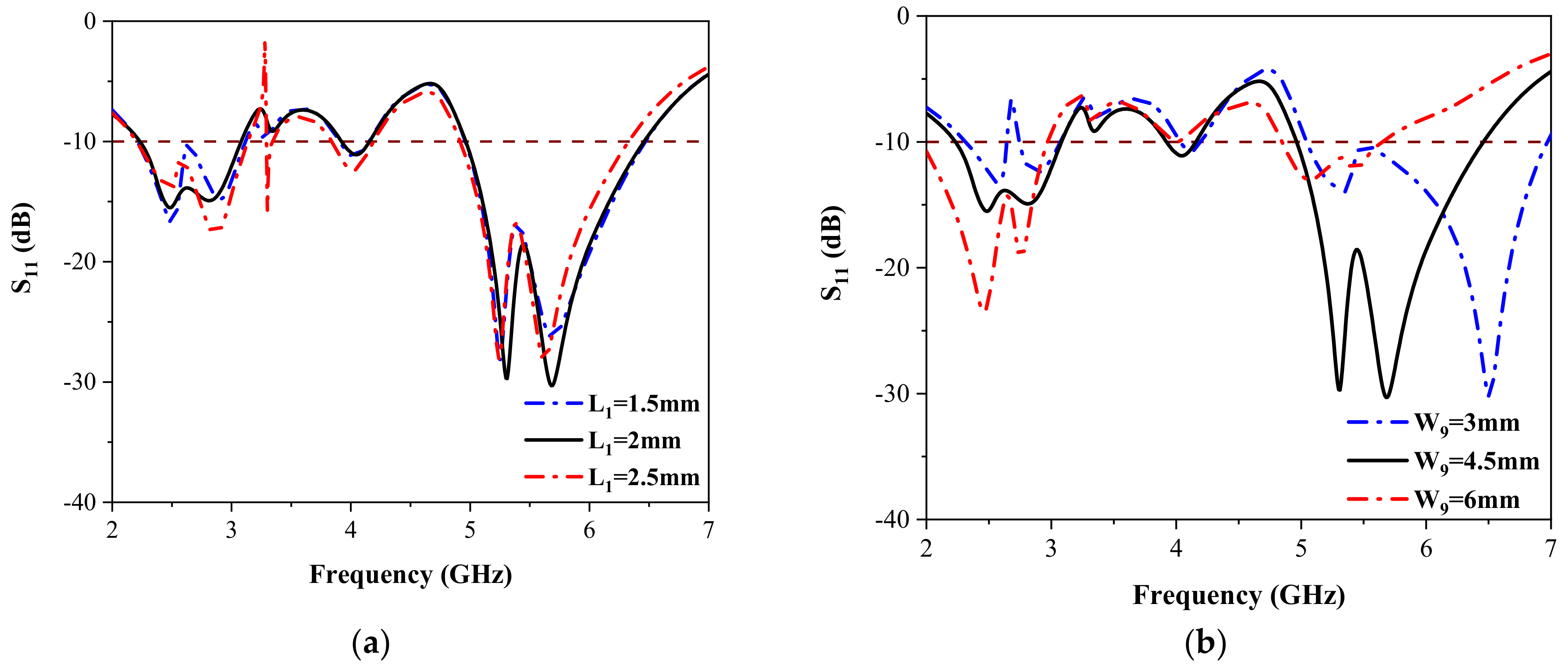
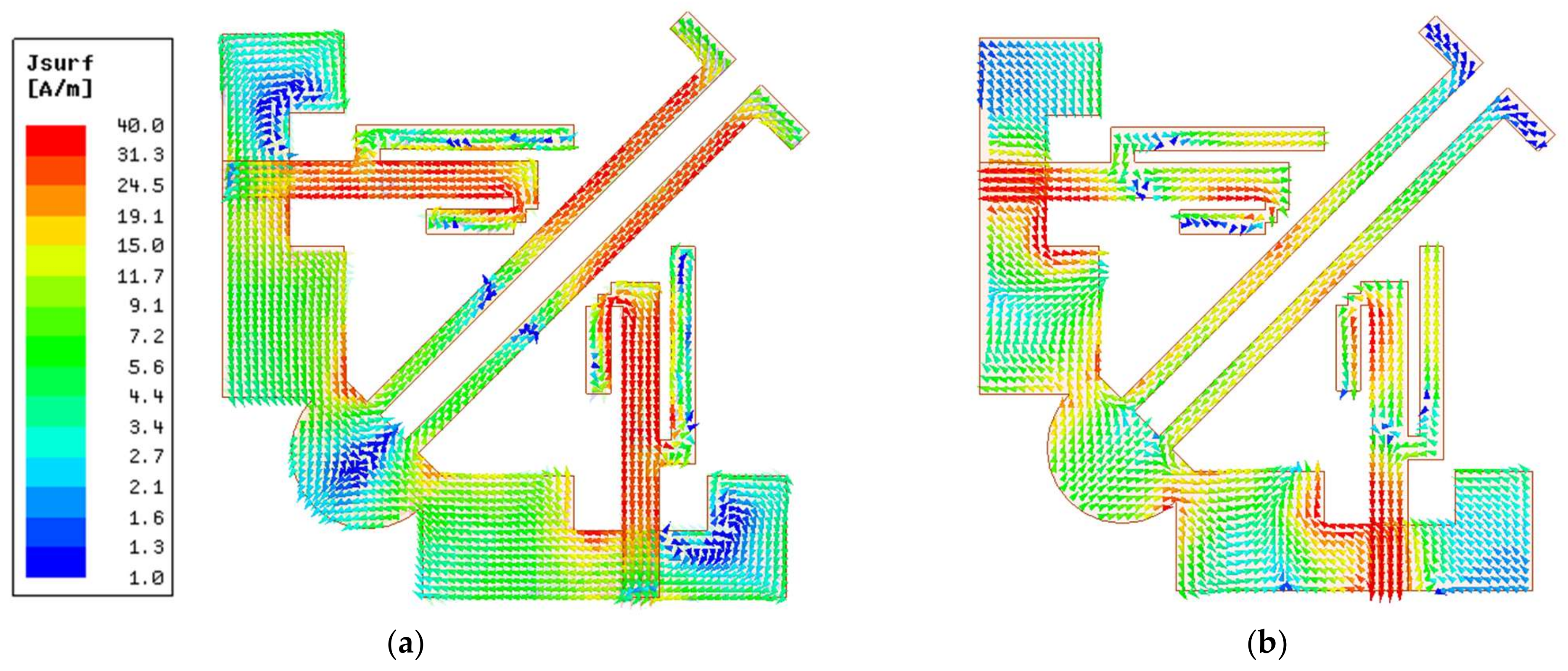
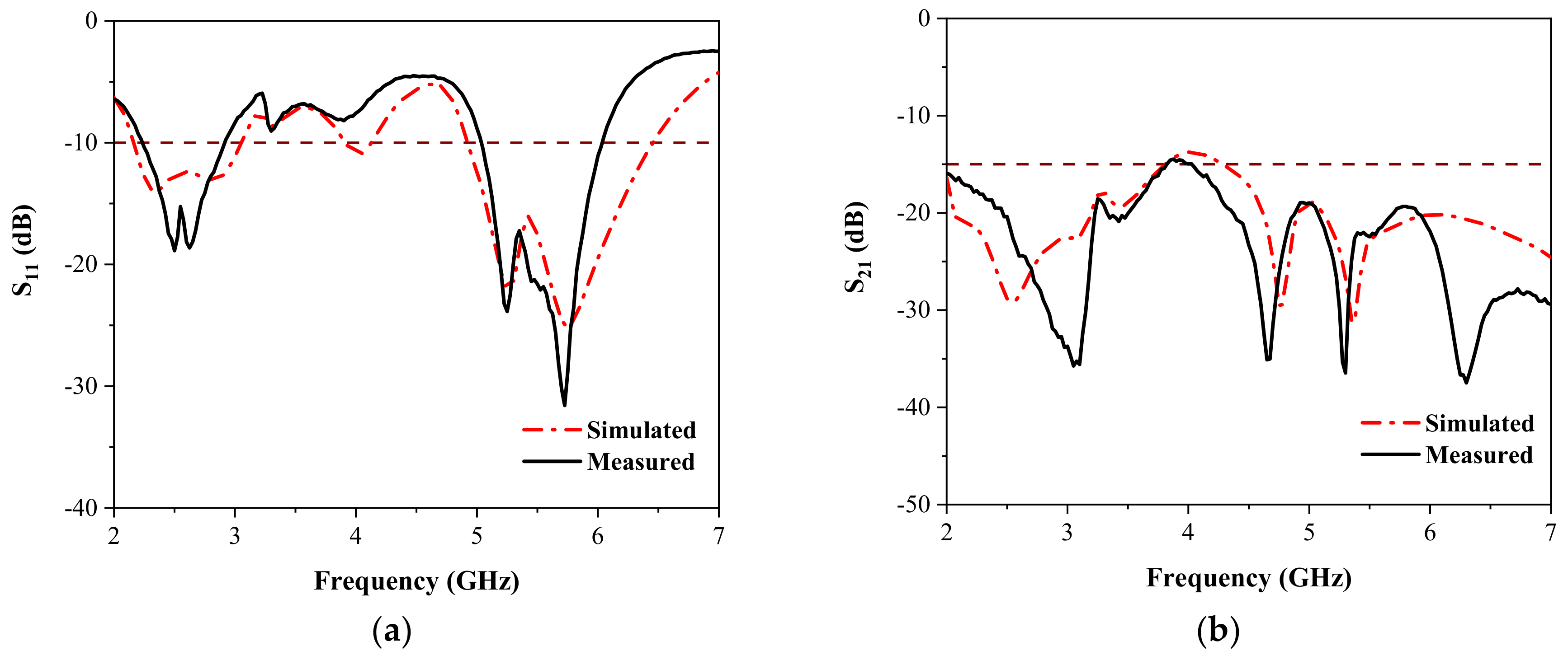
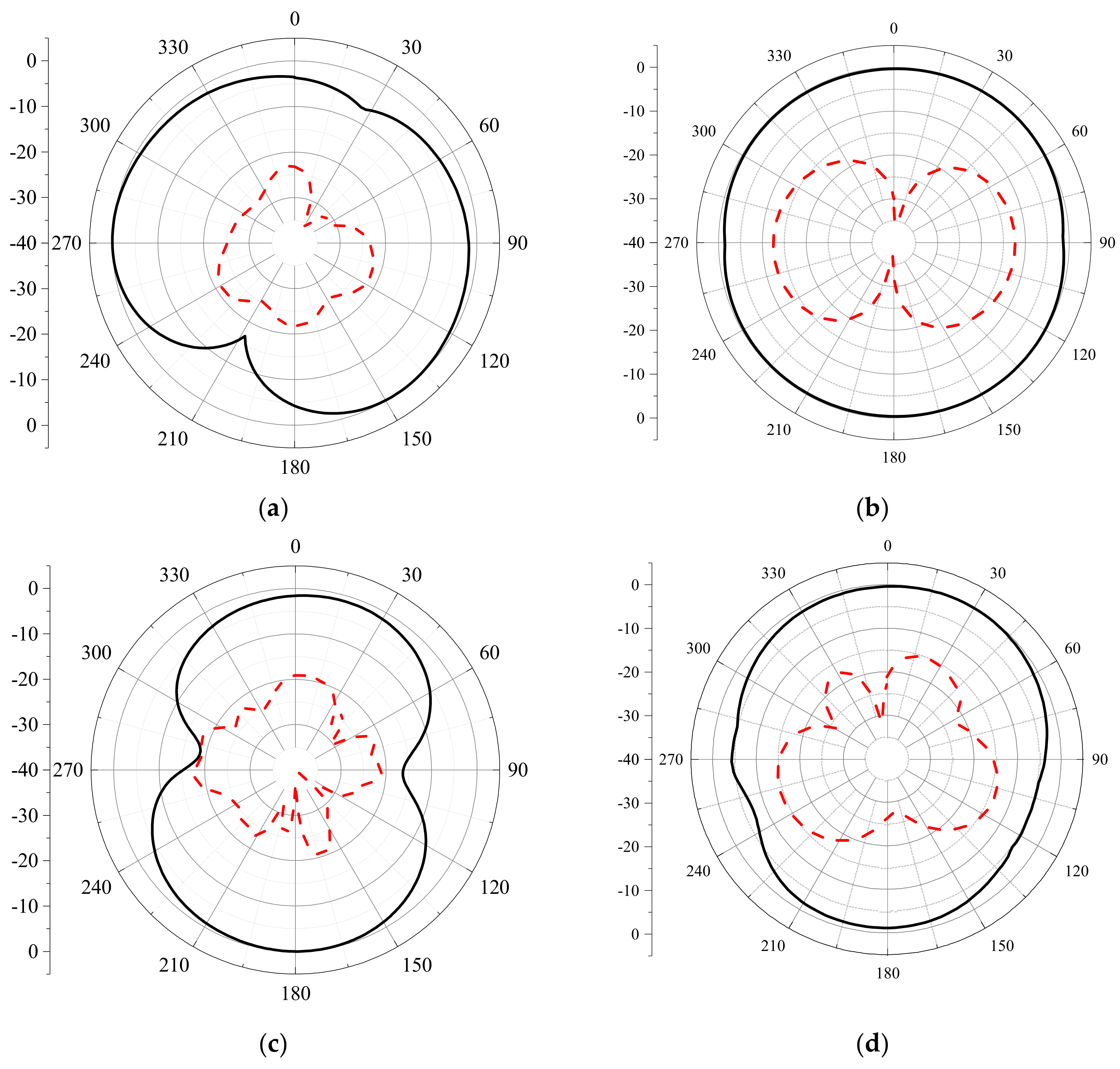
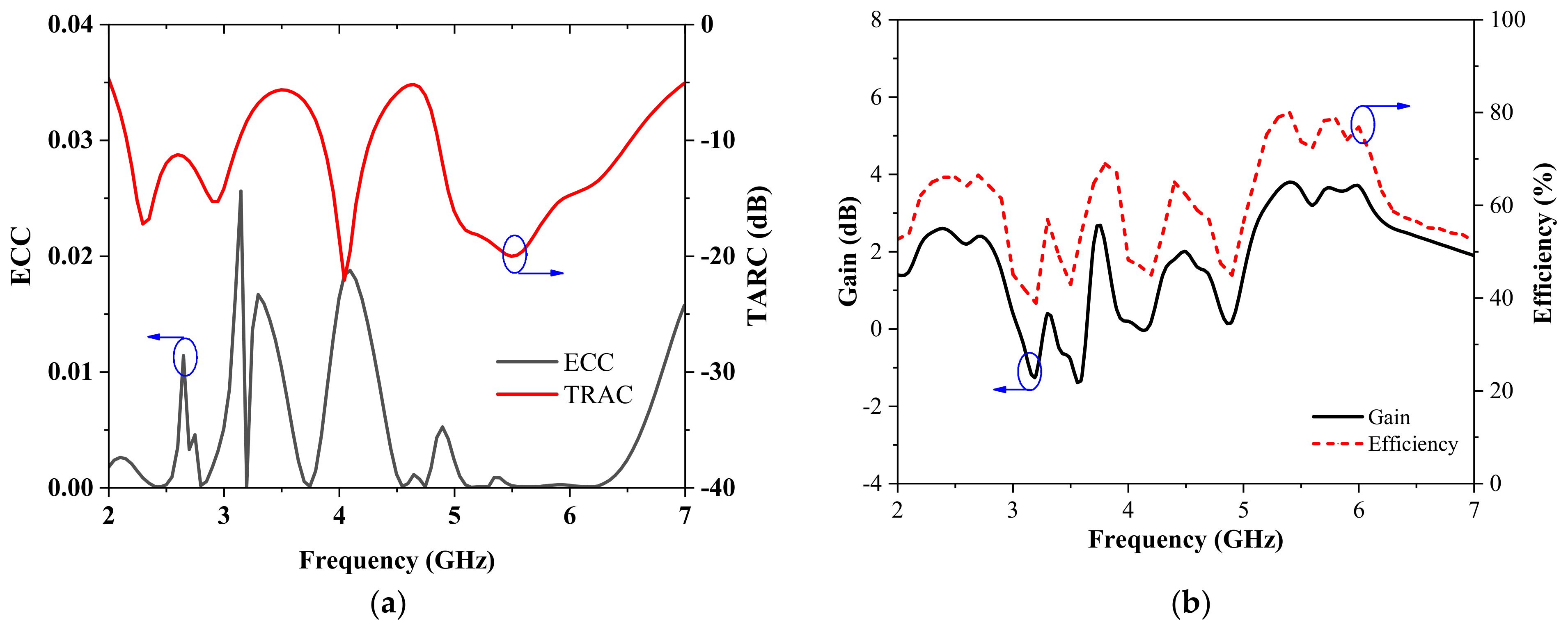
3. Results and Discussion

As shown in Figure 7a, the −10 dB impedance bandwidths of the measured results are 0.65 GHz (2.25–2.9 GHz) and 0.975 GHz (5.05–6.025 GHz), which can cover IEEE 802.11 a/b/g/n/p/ac/ax (2.4–2.497 GHz and 5.15–5.85 GHz) frequency bands. Figure 7b depicts the measured and simulated S21 at both frequency bands. The values of S21 are smaller than −19.5 dB and −19.3 dB at the lower and the higher operating frequency bands, respectively.
At the frequencies of 2.45 GHz and 5.5 GHz, the measured radiation patterns of the fabricated antenna are illustrated in Figure 8. It can be seen from the distribution circle in Figure 8 that the superposition gain and polarization effects of the radiation field generated by the same two ports are excellent. The co-polarization is illustrated by a black solid line, the cross-polarization by a red dotted line. The antenna has a wide beam width at the desired bands, which is suitable for WLAN applications.
The envelope correlation coefficient (ECC) is an important factor used to assess the level of correlation between the communication channels [12,13]. In a MIMO system, the ECC indicates how multiple antennas are independent in the radial direction. To some extent, it can explain the correlation between radiation elements. The calculated ECC of the MIMO antenna are presented in Figure 9a. The ECC parameters of the fabricated antenna can be obtained by Equation (1):
E C C = S 11 * S 12 + S 21 * S 22 2 1 S 11 2 + S 21 2 1 S 22 2 + S 12 2
where S*11 and S*21 are the imaginary components of S-parameters S11 and S21, respectively, and S12 and S22 are the real components of S-parameters S12 and S22, respectively. This shows that the calculated ECC values are very low in both operating frequency bands. The maximum value of ECC at 2.45 GHz and 5.5 GHz is 0.026.
The total active reflection coefficient (TARC) [2] can be used to judge the impact on impedance bandwidth when adjacent antennas work at the same time. The TARC is an important index for reflecting the performance of the MIMO antenna. The TARC parameters of the fabricated antenna can be obtained by Equation (2):
T A R C = S 11 + S 12 2 + S 21 + S 22 2 2
The calculated TARC values are presented in Figure 9a. It is observed that the values of TARC in both operating frequency bands are less than −15 dB, which indicates that the MIMO system is stable.
The measured results of peak gain and efficiency are demonstrated in Figure 9b. The measured efficiencies are larger than 61.4% and 65.6% at the lower and higher operating frequency bands, respectively. The measured peak gains are 2.6 dBi and 3.8 dBi at the lower and higher operating frequency bands, respectively.
In Table 2, the summarized parameters include the operating frequency band, peak gain, minimum isolation and size of the designed antenna. Compared with recently published dual-band MIMO antennas, the presented antenna shows a significant improvement on peak gain. With similar occupied size, the presented antenna shows better isolation and ECCs. With similar peak gain, the presented antenna shows a smaller occupied size. The designed antenna has a better comprehensive performance.

4. Conclusions

A novel MIMO antenna with enhanced isolation and high gain is presented in this paper. The −10 dB impedance bandwidths of the measured results are 650 MHz (2.25–2.9 GHz) and 975 MHz (5.05–6.025 GHz), which can cover 2.4 GHz (2.4–2.497 GHz) and 5 GHz (5.15–5.85 GHz) WLAN frequency bands. The measured isolation and peak gain at both operating frequency bands are larger than 19.3 dB and 3.8 dBi, respectively. The calculated ECCs are smaller than 0.026 at both operating frequency bands. The measured efficiency at the lower and higher frequency bands are greater than 0.65 and 0.61, respectively. The experimental results exhibit that the presented antenna is preferred for WLAN applications.

Author Contributions

Conceptualization, Q.Y.; methodology, Q.C., G.L.; investigation, C.Z. writing—original draft preparation, Q.Y.; writing—review and editing, T.H.L., G.L.; supervision and funding acquisition, G.L. All authors have read and agreed to the published version of the manuscript.

Funding

This research work was partially funded by the Science and Technology Department of Zhejiang Province under Grant No. LGG19F010009, National Natural Science Foundation of China under Grant No. 61671330, and Wenzhou Municipal Science and Technology Program under Grant No. C20170005 and No.2018ZG019.

Institutional Review Board Statement

Not applicable.

Informed Consent Statement

Not applicable.

Data Availability Statement

The data supporting this research article are available upon request to the corresponding author.

Conflicts of Interest

The authors declare that there is no conflict of interests regarding the publication of this manuscript.

References

  1. Madhav, B.T.; Usha, D.Y.; Anilkumar, T. Defected Ground Structured Compact MIMO Antenna with Low mutual Coupling for Automotive Communications. Microw. Opt. Technol. Lett. 2019, 61, 794–800. [Google Scholar] [CrossRef]
  2. Usha, D.Y.; Madhav, T.B.; Anil, K.T.; Sri, K.K.; Pardhasaradhi, P. Conformal Printed MIMO Antenna with DGS for Millimetre Wave Communication Applications. Int. J. Electron. Lett. 2020, 8, 329–343. [Google Scholar]
  3. Murtala, A.; Mohamad, K.R.; Farid, Z.; Adamu, Y.I.; Kabiru, I.J.; Mohd, F.M.; Gajibo, M.; Pramudita, A.A.; Irene, K. A Compact Triband Miniaturized MIMO Antenna for WLAN Applications. AEU-Inte. J. Electron. Commun. 2021, 136, 153–767. [Google Scholar]
  4. Venkateswara, R.M.; Madhav, B.T.; Krishna, J.; Usha, D.Y.; Anilkumar, T.; Prudhvi, N.B. CSRR-Loaded T-Shaped MIMO Antenna for 5G Cellular Networks and Vehicular Communications. Int. J. RF Microw. Comput.-Aided Eng. 2019, 29, 10–1002. [Google Scholar] [CrossRef]
  5. Abdalla, M.A.; Ibrahim, A.A. Design and Performance Evaluation of Metamaterial Inspired MIMO Antennas for Wireless Applications. Wirel. Pers. Commun. 2017, 95, 1001–1017. [Google Scholar] [CrossRef]
  6. Huang, J.; Dong, G.; Cai, Q.; Chen, Z.; Li, L.; Liu, G. Dual-Band MIMO Antenna for 5G/WLAN Mobile Terminals. Micromachines 2021, 12, 489. [Google Scholar] [CrossRef] [PubMed]
  7. Yang, R.; Xi, S.; Cai, Q.; Chen, Z.; Wang, X.; Liu, G. A Compact Planar Dual-Band Multiple-Input and Multiple-Output Antenna with High Isolation for 5G and 4G Applications. Micromachines 2021, 12, 544. [Google Scholar] [CrossRef] [PubMed]
  8. Ou, Y.; Cai, X.; Qian, K. Two-Element Compact Antennas Decoupled with a Simple Neutralization Line. Prog. Electromagn. Res. Lett. 2017, 65, 63–68. [Google Scholar] [CrossRef] [Green Version]
  9. Dou, Y.; Chen, Z.; Bai, J.; Cai, Q.; Liu, G. Two-Port CPW-Fed Dual-Band MIMO Antenna for IEEE 802.11 a/b/g Applications. Int. J. Antennas Propag. 2021, 2021, 5572887. [Google Scholar] [CrossRef]
  10. Chen, Y.S.; Chang, C.P. Design of a Four-Element Multiple-Input-Multiple-Output Antenna for Compact Long-Term Evolution Small-Cell Base Stations. IET Microw. Antennas Propag. 2016, 10, 385–392. [Google Scholar] [CrossRef]
  11. Nadeem, I.; Choi, D.Y. Study on Mutual Coupling Reduction Technique for MIMO Antennas. IEEE Access 2019, 7, 563–586. [Google Scholar] [CrossRef]
  12. Peng, H.; Zhi, R.; Yang, Q.; Cai, J.; Wan, Y.; Liu, G. Design of a MIMO Antenna with High Gain and Enhanced Isolation for WLAN Applications. Electronics 2021, 10, 1659. [Google Scholar] [CrossRef]
  13. Huang, J.; Dong, G.; Cai, J.; Li, H.; Liu, G. A Quad-Port Dual-Band MIMO Antenna Array for 5G Smartphone Applications. Electronics 2021, 10, 542. [Google Scholar] [CrossRef]
  14. Soltani, S.; Lotfi, P.; Murch, R.D. A Dual-Band Multiport MIMO Slot Antenna for WLAN Applications. IEEE Antennas Wirel. Propag. Lett. 2017, 16, 529–532. [Google Scholar] [CrossRef]
  15. Naidu, P.V.; Nhanekula, M.B.; Almustafa, K.M. Design and Performance Analysis of MAZE Shaped Quad Port ACS Fed Tri band MIMO Antenna for V2V and Multi Band Applications. AEU-Int. J. Electron. Commun. 2021, 134, 153676. [Google Scholar] [CrossRef]
  16. Sipal, D.; Abegaonkar, M.P.; Koul, S.K. Highly Isolated Compact Planar Dual-Band Antenna with Polarization/Pattern Diversity Characteristics for MIMO Terminals. IEEE Antennas Wirel. Propag. Lett. 2019, 18, 762–766. [Google Scholar] [CrossRef]
  17. Xi, S.; Huang, J.; Chen, B.; Liu, G. A Compact Dual-band Multi-input Multi-output Antenna for 5G/WLAN/Bluetooth Applications. Microw. Opt. Technol. Lett. 2021, 664, 325–3303. [Google Scholar] [CrossRef]
  18. Deng, J.; Li, J.; Zhao, L.; Guo, L. A Dual-Band Inverted-F MIMO Antenna with Enhanced Isolation for WLAN Applications. IEEE Antennas Wirel. Propag. Lett. 2017, 16, 2270–2273. [Google Scholar] [CrossRef]
  19. Liu, P.; Sun, D.; Wang, P.; Gao, P. Design of a Dual-Band MIMO Antenna with High Isolation for WLAN Applications. Prog. Electromagn. Res. Lett. 2018, 74, 23–30. [Google Scholar] [CrossRef] [Green Version]
  20. Khan, M.S.; Shafique, M.F.; Naqvi, A.; Capobianco, A.; Ijaz, B.; Braaten, B.D. A Miniaturized Dual-Band MIMO Antenna for WLAN Applications. IEEE Antennas Wirel. Propag. Lett. 2015, 14, 958–961. [Google Scholar] [CrossRef]
Figure 1. Structure of the designed MIMO antenna. (a) antenna 1, (b) antenna 2 and (c) antenna 3 (proposed).
Applsci 12 02279 g001
Figure 2. The simulated parameters of three antennas. (a) reflection coefficients, (b) isolation values.
Applsci 12 02279 g002
Figure 3. Structure of the designed MIMO antenna. (a) top view, (b) bottom view.
Applsci 12 02279 g003
Figure 4. The simulated S parameters at different values of (a) L1 and (b) W9.
Applsci 12 02279 g004
Figure 5. Simulated surface current directions. (a) 2.45 GHz, (b) 5.5 GHz.
Applsci 12 02279 g005
Figure 6. The photographs of the fabricated antenna. (a) top view, (b) bottom view.
Applsci 12 02279 g006
Figure 7. Simulated and measured S-parameters of presented antenna. (a) S11; (b) S21.
Applsci 12 02279 g007
Figure 8. Radiation shapes of the fabricated antenna: (a) E-plane at 2.45 GHz, (b) H-plane at 2.45 GHz, (c) E-plane at 5.5 GHz, and (d) H-plane at 5.5 GHz.
Applsci 12 02279 g008
Figure 9. (a) Calculated ECC of the fabricated antenna and (b) measured peak gain and efficiency.
Applsci 12 02279 g009
Table 1. Parameters of the presented antenna (unit: mm).
ParameterW1W2W3W4W5W6
Value114.418137.21
ParameterW7W8W9W10W11Ws
Value1104.55.64.150
ParameterL1L2L3L4L5L6
Value241123
ParameterL7L8L9L10L11Ls
Value116.533.541.5250
Table 2. Comparison with recently published papers.
ReferenceOperating Bands
(GHz)
Isolation
(dB)
Peak Gain
(dBi)
ECCSize
(mm3)
[14]2.4–2.5
4.9–5.8
>142.5<0.2746 × 20 × 1.6
[15]2.25–2.41
4.7–6.25
>182.96<0.248 × 48 × 1.6
[16]2.3–2.5
5–5.2
>202.01<0.0538 × 19 × 1.6
[17]2.28–2.7
4.96–6.1
>152<0.0646.5 × 46.5 × 1.6
[18]2.4–2.48
5.15–5.83
>153.1<0.277.5 × 52 × 1.6
[19]2.1–2.8
5.0–5.7
>203.2<0.0174 × 47.3 × 1.6
[20]2.4–2.5
5.1–5.8
>153<0.119 × 23 × 1.6
This work2.25–2.9
5.05–6.025
>19.33.8<0.0350 × 50 × 1.6
Publisher’s Note: MDPI stays neutral with regard to jurisdictional claims in published maps and institutional affiliations.

