Article

Numerical Study of Wave Effect on Aircraft Water-Landing Performance

1
College of Aerospace Engineering, Nanjing University of Aeronautics and Astronautics, Nanjing 210016, China
2
Key Aviation Scientific and Technological Laboratory of High-Speed Hydrodynamic, China Special Vehicle Research Institute, Jingmen 448035, China
3
National Research Council—Institute of Marine Engineering, 00128 Rome, Italy
*
Author to whom correspondence should be addressed.
Appl. Sci. 2022, 12(5), 2561; https://doi.org/10.3390/app12052561
Submission received: 5 January 2022 / Revised: 23 February 2022 / Accepted: 24 February 2022 / Published: 1 March 2022
(This article belongs to the Section Aerospace Science and Engineering)

Abstract

:
Aircraft, such as amphibious planes, airliners, helicopters and re-entry capsules, are frequently subject to impacting loads from water-landing/ditching on various free surfaces, especially under wave conditions. Understanding and quantifying the water-landing/ditching performance on wave surfaces are of fundamental important for the design and certification of crashworthiness in the field of aerospace engineering. This study aims to numerically assess the effect of wave surface on water-landing process of an amphibious aircraft. The numerical implementation is realized in Reynolds-averaged Navier–Stokes (RANS) framework by combining finite volume method (FVM), volume of fluid (VOF) approach and velocity-inlet wavemaker. The temporal-spatial characteristic of numerical wave and the accuracy of presented model are, respectively, validated by analytical wave and convergence studies. The aircraft landing simulations with different free surface conditions, i.e., calm water, regular wave with different wave heights are then performed and quantitatively compared through several physical parameters, including acceleration, velocity, pressure, pitch angle and free surface deformation. It was found that the aircraft regular wave-landing process experiences several unique stages comparing with the calm-water-landing case. The results clearly confirm that wave surface can influence the aircraft landing performance to a great extent. The fundamental mechanism is found to be that the wave surface slope and wave particle velocity remarkably change the impacting position and effective impacting velocity of the aircraft.

1. Introduction

In the aerospace industry, aircraft water-landing/ditching is one of the most concerned topics that has attracted tremendous attention from both engineering and academic communities during the past decades. This event is described as planned and controlled aircraft landing on free-surface due to extreme emergencies, e.g., bird strike, thunderstorm weather, fuel exhaustion, crew error, terrorist hijack, mechanical failure, etc. The crew, with the aircraft under control, deliberately and gently lands on water according to recommended procedures given in the flight manual [1]. It is categorized into four stages [2]: approaching, impacting, landing and floating, among which, the impacting and landing are the fatal stages during this process and result in complex fluid–structure interactions [3]. Furthermore, the phenomenon and dynamic physics of the ditching process could be more sophisticated when severe wave surfaces are considered. Consequently, the ditching performance with respect to the safety are essentially matters in the aircraft design and certification process.
The previous document [4] shows that there are many tragic aircraft crash accidents within 219 shocked emergency ditching since 1938. Several well-known airline plane ditching attempts have been analyzed [1,5]. Additionally, helicopter crash mishaps occurring due to multiple reasons. Many investigations on helicopter ditching crash have been published [6,7,8,9,10] and conducted that the probability of experiencing a capsize is highly dependent on the sea state level which depends on the height and period or slope of wave. Summing up, many airline (fixed-wing aircraft) accidents and helicopter mishaps categorized as wave landing/ditching encountered uncontrollable situations and ended in tragedies. Therefore, the assessment of aerodynamics and hydrodynamics performances of aircraft landing/ditching on wave surface are required at the early stage of aircraft design procedure. Particularly, the general features of wave parameter effect on the aircraft landing/ditching process need to be analyzed.
There are three methods to address water impacting and landing problems in the literature, including theoretical analysis, experimental test and numerical simulation. A historical review of research related to water impact between 1929 and 2003 can be found in Sneddon et al. [11] who provides the milestones of research and includes the theoretical and experimental developments. Hughes et al. [12] extended significantly on Sneddon’s review to include researches between 1986 and 2006 by summarizing the major progress on helicopter water impact problem. Qu et al. [4] reviewed earlier developments in the area of aircraft water-landing by NASA Langley Research Center between 1940 and 1975 and concluded the weaknesses of theoretical method and experimental research, respectively. Instead, numerical simulation applications in the field of aircraft water-landing are drawing increasing attention in the academic and industrial communities due to the strengths, e.g., taking into account the complex aircraft configuration and the near field of the surrounding fluids, providing high-resolution results and consuming less money and time.
Various numerical results in the field of aircraft calm water-landing/ditching have been published through Arbitrary Lagrangian–Eulerian (ALE) method [13,14,15,16,17], the messless Smoothed Particle Hydrodynamics (SPH) method [15,16,17,18,19,20] and Finite Volume Method (FVM) [4,21,22,23,24]. Early studies were mainly focused on the feasibility of the ALE and SPH approaches. In 2002, Airbus A321 calm water ditching simulation was performed by Ortiz et al. [13]. Later, Pentecote and Vigliotti [14] employed ALE-FE method to simulate a full-scale WG30 helicopter impacting on calm water with a vertical velocity. They concluded that the over-estimated pressure and acceleration are partly caused by that the air layer between the fuselage and water surface is not modelled in the simulation. The well-approved point from Refs. [15,16,17] is that the ALE technique is an efficient formulation for both vertical impact and landing simulations, but difficult to accurately capture air-water-structure interface, the SPH method provides accurate results of ditching simulation due to free mesh strategy and high-resolution water spray but may suffers from huge computational cost. Recently, Xiao et al. [18] developed an in-house SPH code and successfully applied it to predict calm water ditching process of capsule [19] and helicopter [20]. The influences of the initial pitch angle on overload, kinematic dynamics and pressure distribution were detailed. Their results show that the initial pitch angle has a noticeable effect on the load of the aircraft, the splashing jet generated from the belly is regarded as the strong interaction of the aircraft with water surface, and the pitch motion of the aircraft is caused by the hydrodynamic overpressure and suction.
In fact, as presented in this study, the aerodynamic characteristic plays a non-negligible role in the aircraft water-landing/ditching process. Therefore, the FVM approach might be the reasonable choice for the aircraft landing/ditching simulation due to the outstanding advantages in capturing the complex air-water mixing phenomenons. Early confidence of numerical results through FVM approach was gained by Wick et al. [21] and Streckwall et al. [22]. Wick et al. [21] studied the effect of initial drop velocity on an unmanned air vehicle (UAV) vertical drop performance. The simulated behaviour of the pressure time-histories was in good agreement with experimentally measured values. Streckwall et al. [22] used the non-deforming mesh strategy to compute the path of the aircraft fuselage landing on calm-water surface and the numerical results were comparable with the test data. They concluded that the high pressure in the front part of the fuselage and the negative pressure at the rear part lead to upward and downward forces, which result in the deceleration and pitch-up motions of the aircraft model. Further study, carried out by Guo et al. [23], numerically simulated the planned landing of a transport airplane on the calm water and summarized that as the pitching angle increases, the maximal normal force and the pitching motion becomes much gentler. Qu et al. [24] proposed a new global-moving-mesh (GMM) method based on Guo’s work, and studied the ditching characteristics of transport aircraft (NACA2929 model). By using GMM method, Qu et al. [4] further detailed the effects of initial pitching angle and initial descent velocity on the performance of aircraft water-landing in calm water. They concluded that the pressure distribution on the fuselage in the water region plays a decisive role in the water-landing process, the negative pressure around the rear part of the fuselage is attributed to the Coanda effect and can create a nose-up pitch motion, a larger initial pitching angle is recommended to improve safety due to that the larger initial pitch angle can lead to a smaller horizontal and vertical loads, and with the increase in the initial descent velocity, the impact peak value of the vertical load is of larger magnitude.
Most aforementioned publications are limited to the calm water surface and mainly focus on the effects of the initial parameters on the aircraft and helicopter water-landing and ditching performance, including initial velocity and pitch angle. Recently, the aircraft wave-landing problem was gain attention by few researchers in the literature. In 2019, by using the SPH method, Woodgate et al. [25] presented time–history results of the AW101 helicopter wave ditching in sea state 4, including acceleration, displacement and velocity. In 2020, Feng et al. [26] proved that the numerical wave-making method can be used in the seaplane wave-landing study through an ALE-based framework. More inspired works [27,28] were provided to further study the influence rules of wave height and initial wave position on the characteristics of the aircraft wave-landing. Zhao et al. [27] studied the extreme impact load of a high wing-tail regional aircraft during the sea state 4 landing process. The effect of wave height on the impact load and peak values are detailed. They concluded that the vertical and horizontal impact peaks are monotonously related to the wave height. In 2021, Xiao et al. [28] investigated the effects of initial wave-landing position and pitch angle on a helicopter. The general conclusions are that the dynamic motion and hydrodynamic behaviour of the helicopter ditching on wavy water are significantly different from those of ditching on calm water; ditching on the crest position is the best option with different initial pitch angles.
However, the present knowledge is still insufficient for the aircraft wave landing problem. Particularly, the behavior and mechanisms of aircraft water-landing with regular waves are not fully explored. Therefore, in the present study, we primarily aim to provide a comprehensive understanding of the aircraft water-landing process with different wave surfaces and to further investigate the mechanism of wave height effect on the aircraft regular wave-landing performance. A three-dimensional (3D) numerical non-breaking wave is generated by combining the velocity-inlet/static boundary wavemaker and the momentum-absorbing method. The incompressible RANS equations, volume of fluid (VOF) function, turbulence model and six-degrees-of-freedom model are solved by the CFD packages STAR CCM+. Based on the results by Chen et al. [29] that the compressibility effects are not expected to affect the general trends of the impact load and play non-dominated roles in the whole ditching process. Moreover, the ditching speed of the aircraft in this study is in the range of M a 0.11 , thus the compressible fluids are not considered. The remainder of the paper is organized as follows. In Section 2, the FVM-RANS-based computational method, wavemaker and case setup for the amphibious aircraft water-landing simulation are detailed. Numerical validation cases are then presented in Section 3 to verify the correct implementation and accuracy of the wavemaking method and numerical model. In Section 4, several case studies are performed to investigate the aircraft landing performance with different wave surfaces. The conclusions of this study are presented in Section 5.

2. Computational Method

2.1. Governing Equations and Numerical Schemes

The governing equations are the unsteady and incompressible RANS equations, written as:
V = 0
V t + V · V = 1 ρ p + 1 ρ τ + g + S
where t denotes time, V is the velocity vector, ρ the density, p the pressure, τ the stress tensor, g the gravitational acceleration vector, and S the source term of a sponge layer that absorbs wave reflections from the outlet boundary.
To determine the free surface of air–water interface, the widely used VOF method [30] is applied. This method capture the interface between two or more immiscible fluids by introducing volume fraction for each fluid phase governed by the following equation:
α t + α · V = 0
where α is an indicator phase function, defined as the amount of water per unit volume at each computational cell. If α = 1 , the cell is full of water; if α = 0 , the cell is full of air; in other cases, the cell belongs to the interface. Based on the value of α , the properties of fluid in each cell can be numerically determined. Moreover, to accurately capture the interaction and relative motion between the aircraft and free surface, the six-degree-of-freedom (6DOF) model is adopted which can solves the rotation and translation of the center of mass of the object. The rigidly moving mesh strategy in the Dynamic Fluid Body Interaction (DFBI) module is employed to deal with the relative motion between the fluid and the landing object. This strategy moves or/and rotates the whole computational mesh rigidly along with the object at each time step according to the solution of the 6DOF model [16] and has been widely used in the field of the aircraft water-landing/ditching problems [22,23,24,28]. These numerical publications also illustrated that the rigidly moving mesh strategy is able to handle the large motion aircraft with range of pitch angle 0–40 ° . In addition, the overset mesh approach is not employed in this study based on the consideration that for the aircraft ditching problem, the aerodynamics and hydrodynamics both play non-negligible effect on the ditching performance, thus the total grid number (background mesh and overset mesh) may be larger than that of rigidly moving mesh strategy. In contrast, by using the rigidly moving mesh, the whole computational domain and boundaries are able to move together with the aircraft, which can avoid the high computational cost and large data interpolation between the background mesh of the fluid domain with overset mesh around the body. The details of the rigidly moving mesh strategy can be found in Refs. [31,32]. In addition, the cavitation model is not employed in this study for numerical stability and time efficiency considerations. This treatment may affect the local pressure accuracy at the rear-fuselage region, but it is less influence on the overall tendency of the impact loads and the aircraft movement [4].
The governing equations are numerically solved by STAR CCM+. The k ω shear stress transport (SST) turbulence model is adopted to solve the stress tensor based on the research of turbulence model effect in numerical wave simulation [33]. The SIMPLE algorithm is applied to address the pressure–velocity coupling. The second-order implicit scheme is employed to deal with the time advancing. The convection terms and diffusion terms are discretized by second-order upwind and second-order central difference schemes, respectively. For the VOF transport in Equation (3), the high-resolution interface capturing (HRIC) scheme is employed to discrete the convection term, and the implicit scheme is used to discrete the unsteady term. More details of these numerical schemes can be found in Ref. [31].

2.2. Wavemaker

The velocity-inlet/static boundary wavemaker is realized by imposing the wave phase velocities and phase functions at the inlet boundary cell face of the computational domain. Airy’s wave theory [34], also referred to as the linear wave theory, is applied to describe the wave velocities and elevation. For regular wave simulations, the wave elevation and velocities at the inlet boundary are given by:
η ( x , t ) = A c o s ( k x ω t )
V x ( x , z , t ) = A ω c o s h ( k [ z + d ] ) s i n h ( k d ) c o s ( k x ω t )
V z ( x , z , t ) = A ω s i n h ( k [ z + d ] ) s i n h ( k d ) s i n ( k x ω t )
where η ( x , t ) is the transient wave elevation at the x position; V x ( x , z , t ) and V z ( x , z , t ) are the velocity components in the x and z directions, respectively; A = H / 2 is the wave amplitude, H is the wave height; d is the water depth. The directions of x, y, z and the velocity-inlet boundary are shown in Figure 1a. The wavenumber k and angular wave frequency ω satisfy the dispersion relation:
ω 2 = g k t a n h ( k d )
To minimize the wave reflections from the outlet boundary, a wave-absorbing zone shown in Figure 1a is set up at the end of the computational domain. This is also called the damping zone or sponger layer [35]. The absorbing momentum source S added in Equation (2) is given by [36]:
S i ( x ) = ρ ( μ C 1 v i + ρ C 2 v i | v i | ) exp ( x x s x e x s ) n s 1 exp ( 1 ) 1 , x e x x s
where subscript i represents the x, y and z directions; ρ , μ and v i are the density, viscosity and velocity of the cell in the computational domain, respectively; following Peric and Abdel-Maksoud [37], the empirically determined parameters are taken as C 1 = C 2 = 10 and n s = 2 ; x s and x e are y coordinate of start and end of absorbing zone, as sketched in Figure 1a.

2.3. Case Setup of Aircraft Water-Landing Problem

A full-scaled amphibious aircraft is employed to investigate the wave-landing performance, the nacelle and tip float beam of this aircraft are removed due to these two parts have negligible effects on hydrodynamic and aerodynamic forces. Figure 1b shows the Cartesian grid of the numerical model as well as the cross-section grid around the flap and step in the forward and spanwise directions. Only half of the physical domain is numerically simulated due to the symmetry of the aircraft configuration with respect to the x z -plane. Therefore, three degrees of freedom of the aircraft are released during the simulation, including the translation of the horizontal (x) and vertical (z) directions and the rotation of the spanwise (y) direction. This half model is 36 m in the x direction, 18 m in the y direction and 49,000 kg in weight. The computational domain is about 5 times of half aircraft model size. The total cell of the baseline numerical model is 18.4 million for calm water and wave landing simulations. Three refined grid regions along the x direction, namely, front, aircraft and wake refinement, are defined to accurately capture the flow features and dynamic of free-surface. Over 14 million cells are used in the aircraft refinement region combing with 15 grid layers in the viscous boundary area.
As shown in Figure 1a, the flow field of a three-dimensional rectangular computational domain is divided into an air zone and a water zone, denoted in the VOF function by 0 and 1, respectively. At the inlet boundary of the computational domain, a velocity-inlet wavemaker is established to specify the wave elevation and the horizontal and vertical water particle velocities, as presented in Section 2.2. At the outlet boundary, the pressure outlet boundary condition with hydrostatic pressure and zero wave elevation is applied. The free-slip condition is specified at the sidewalls and top face of the computational domain. The wall condition is adopted at the bottom surface to simulated the finite-depth water tank.
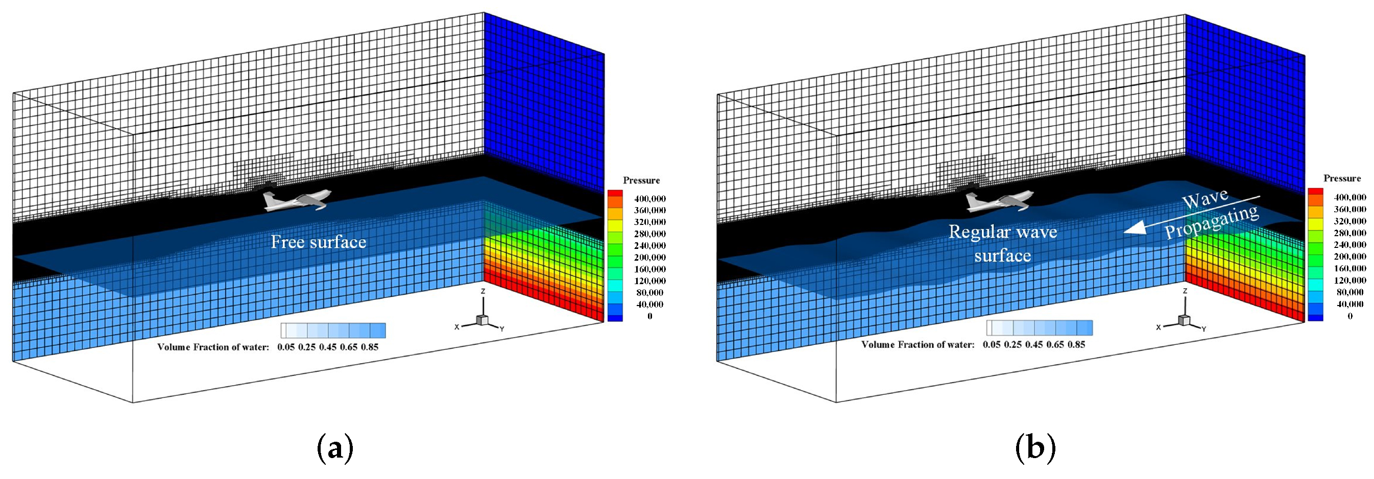
Figure 2 shows the initial flow field of calm water and wave surface landing simulations. The surface tension at the air-water interface is assumed to be negligible. Initial hydrostatic pressure is assigned in the water zone, and the reference pressure is initially imposed on the entire computational domain. The initial landing speed V x = 40 m/s and V z = 4 m/s with pitch angle α = 6 degree is selected. The wave height H = 2 m, wave length L = 40 m and wave period T = 5.06 s are employed to study the wave landing performance. With these numerical setup parameters, we simulated aircraft landing into calm water and wave field with a time step size of 2 × 10 4 s.

3. Validation of Numerical Model

3.1. Validation of Numerical Wave

The regular wave case is carried out to validate the accuracy of the numerical wavemaker. The wave parameters used in this section are based on the hypotheses of non-breaking wave [38] and intermediate water depth [39]. Specifically, as detailed in Section 2.3, wave height is 2.0 m, wave length is 40 m, wave period is 5.06 s and water depth is 10 m. Accordingly, the wave steepness H / L (the ratio of wave height to wavelength) and d / L (the ratio of water depth to wavelength) are approximately 0.05 and 0.25. Thus, the wave is non-breaking and the wave phase speed has only a negligible influence due to the water depth. The methodology given in Section 2 is applied to derive the analytical regular wave components. These wave components are used to determine the wave elevation at the inlet boundary, as given by Equation (4), and the corresponding horizontal and vertical water particle velocities are given by Equations (5) and (6). These quantities are then inputted into the CFD simulation through STAR CCM+ package.
Figure 3 shows the computational grid of regular wave case. The grid used in this section is structured and locally refined at the air-water two-phase interface to improve the accuracy of wave simulation. Particularly, a very fine grid is equally discretized in x, y and z directions within the region of wave elevated from z = H to z = H as shown in Figure 3b. Furthermore, a cell size growth rate of 1.2 along the wave propagated direction is adopted in the absorbing zone, thus reducing the total cell number and computational cost. Based on the mesh and time step independence studies by [28,33], the refined grid resolution near the interface and time step in this section are adopted as L / x = 60 , L / y = 60 , H / z = 40 and T / d t = 1000 . Three wave elevation probes are set up at different distances from the inlet of the domain with an interval distance L = 40 m, as shown in Figure 3a.
The comparisons between the wave elevations obtained by the CFD simulation and the analytical calculation are shown in Figure 4. The target wave elevations colored by black lines are the resolved waves given by the aforementioned analytical wave in Section 2.2, and the wave elevation depicted with red curves are the result of numerical simulation. The numerical wave elevations at probe P1–P3 match well with the analytical values. Therefore, the combination of the wavemaker and selected grid resolution and time step is able to meet the requirements of numerical wave generation.

3.2. Mesh and Time Step Size Convergence Studies

The validation cases for the ditching problem have been achieved in our previous studies, including the high-speed flat plate ditching [28], wedge water-entry [40], aerospace capsule water-landing [41] and regional aircraft ditching [42]. The comparison between the numerical results and experimental data in these publications shows that the numerical framework employed in this study can provide results with satisfactory accuracy for the ditching problems.
Further, in order to verify the correct implementation of the numerical model and to show that the selected mesh and time scale are suitable for a proper analysis, the mesh and time step convergence studies are conducted for the calm water landing event. As shown in Table 1, three different grid resolutions are adopted in the region of the air-water interface and the aircraft model. Figure 5 shows the results of the vertical and horizontal accelerations obtained by these three meshes with the same time step Δ t = 2 × 10 4 s. It can be seen that the solution converges asymptotically as cell number increases, and the overall time history and the peaks are very close by comparing the results of medium and fine meshes. Similarly, as shown in Table 2, the time step refinement study is carried out by varying time step size with the same medium mesh. Figure 6 presents the time-history results of the vertical and horizontal accelerations of the aircraft with different time step. It shows that the solution convergence is achieved as the time step decreases from 2 × 10 4 s to 1 × 10 4 s, especially in the peak region (zoom-in view) where the values tend consistent. Therefore, based on the consideration of high efficiency and accuracy of the simulation, the medium grid resolution and time step 2 × 10 4 s are selected as the baseline numerical setup throughout the paper.
Moreover, for the aircraft wave-landing simulation case, the grid resolution at the air-water interface is also guaranteed based on the results of numerical wave and mesh convergence validations. Figure 7 shows the computational global and zoom-in grid of the medium mesh. As can be seen in the second zoom-in view, the grid size in the x and z directions is about Δ x = 0.5 m and Δ z = 0.05 m. Accordingly, the quantified grid resolution is L / Δ x = 80 and H / Δ z = 40 . It is comparable with the grid resolution in the section of numerical wave validation. Thus, the grid resolution adopted in the numerical model of the aircraft wave-landing case is able to predict accurate wave-landing characteristics.

4. Results and Discussions

4.1. Calm Water vs. Wave Water

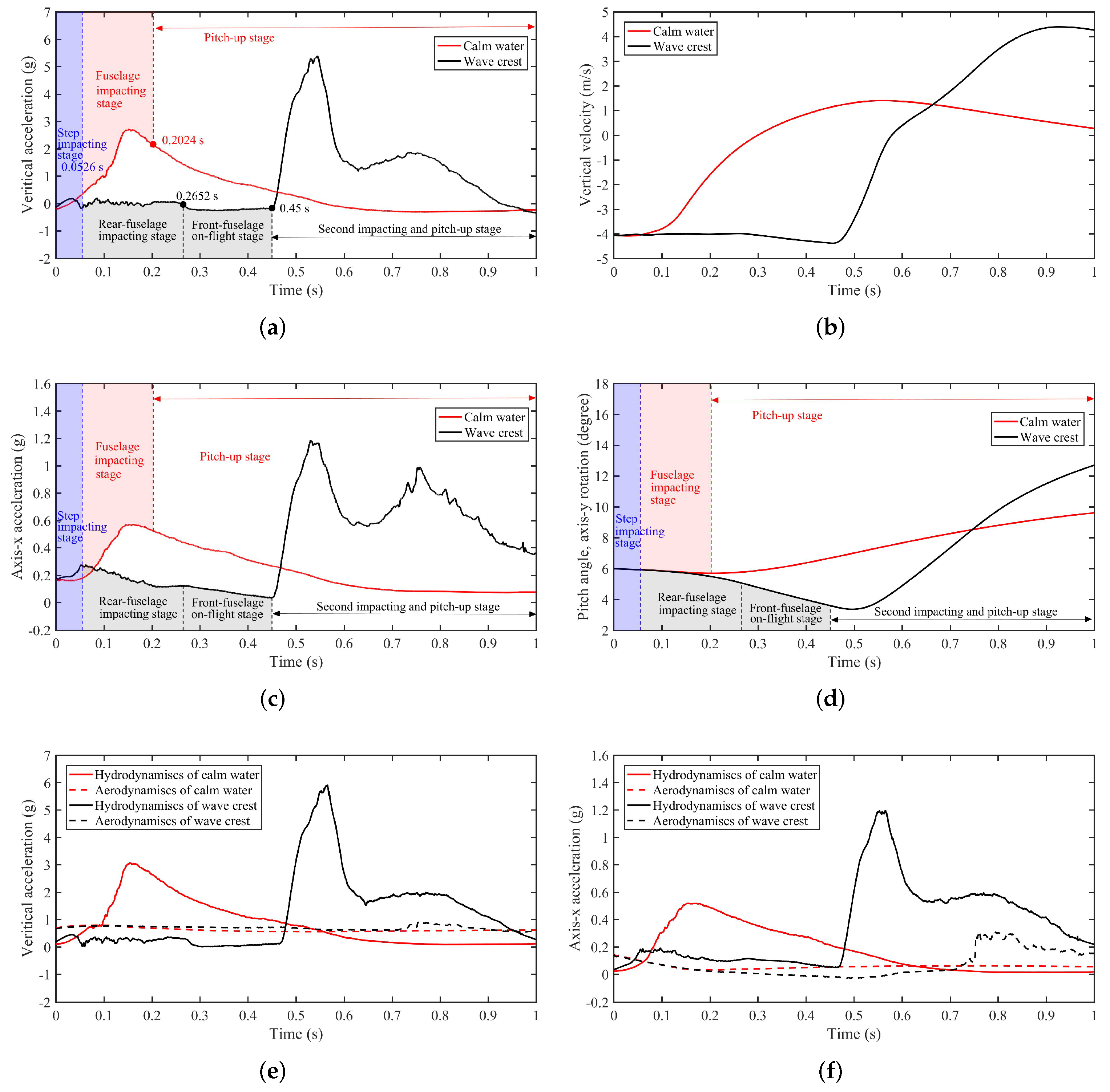
The numerical results of aircraft movement of calm water and regular wave-landing events are depicted in Figure 8. Particularly, the separated accelerations by hydrodynamic and aerodynamic forces shown in Figure 8e,f are calculated by the integration of pressure distribution on the fuselage and wing-tail surface. The separated hydrodynamic acceleration is based on the fact that the interaction between fuselage and fluid is dominated by the hydrodynamic pressure on the fuselage [4]. Because the hydrodynamic force generated by the fuselage is far larger than the aerodynamic force of the fuselage since the density rate of water and air is 998 / 1.225 , approximately 814.7 . By comparing the red and black curves, it is found that the overall tendency of aircraft acceleration, velocity and pitch angle in calm water case and wave crest case is totally different. For the convenience of further exploring the mechanism of these two cases, the early process of water-landing is separately described as three distinctive stages according to the impacting position of the fuselage, variation of acceleration and pitching angle of the aircraft, i.e., step impacting stage, fuselage impacting stage and pitching-up stage.
Figure 9 shows three transient snapshots ( t = 0 , 0.5 and 1.0 s) of the whole computational domain movement, free surface evolution and mesh around the aircraft model during the calm water and wave crest landing process. Note that the snapshot in the 2D XOZ plane shows the whole computational domain movement. It can be seen that by using the rigidly moving mesh strategy in DFBI module, the computational domain is moving with the rotation motion of the aircraft and the free surface can be maintained with the same level in the ground-fixed coordinate XYZ, thus the reality of the simulation is guaranteed. In addition, the water spray around the fuselage is also shown. Thus, the rigidly moving mesh used in this study is able to deal with the movement of the aircraft in the calm water and wave surface landing simulations.
The first stage is named as step impacting stage due to the fact that the impacting position is located at the step area and the variation of aircraft movement for calm water case and wave crest case are similar during t = 0–0.0526 s. In contrast, the obvious differences in acceleration time–history curves are observed between these two cases when t > 0.0526 s. For the calm-water-landing case, the acceleration in the z (vertical) and x directions dramatically increase to maximum ( a z m a x = 2.795 g and a x m a x = 0.556 g) in fuselage impacting stage, and then monotonically decrease in pith-up stage from t = 0.2024 s to t = 1 s. Notably, the pitch angle of aircraft increases in pitch-up stage as shown in Figure 8d. For wave-landing case, the aircraft experiences rear-fuselage impacting stage and front-fuselage on-flight stage from the time period of t = 0.0526–0.2652 s to t = 0.2652–0.45 s with small oscillation of vertical acceleration as plotted in Figure 8a. After that, the accelerations rapidly increase to maximum ( a z m a x = 5.381 g and a x m a x = 1.186 g) and then reach the second peak, as shown in Figure 8a,c during the second impacting and pitch-up stage. Note that the variation tendency of aircraft pitch angle during the whole wave-landing process is changed from diminution to growth because of the change in hydrodynamic forces. Furthermore, comparing the time–history of accelerations between calm water-landing and wave-landing, it can be concluded that the wave field can increase the aircraft overload by approximately twice and obviously influences the aircraft landing process.

4.1.1. Step Impacting Stage

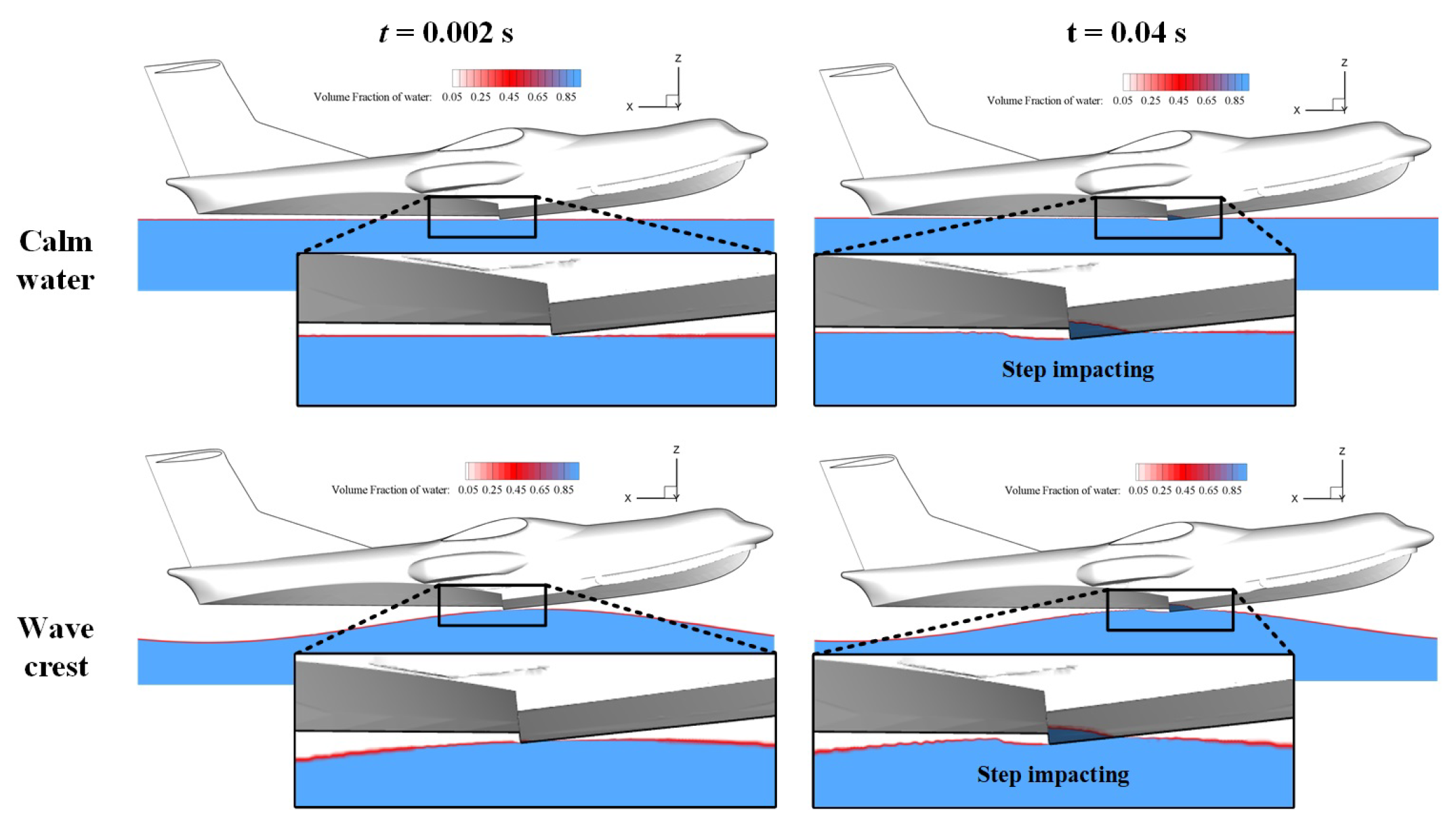
During the step impacting stage, the increment of the vertical and axis-x accelerations are small for both calm water and wave crest landing cases as plotted in Figure 8a,c (blue shaded square). The reason lies in the combining of the deadrise angle of the fuselage and the initial pitch angle of the aircraft, which leads most parts of the fuselage not touch the water except for the step part. As evidenced in Figure 10, the impacting and witted area is small. Note that to highlight the interaction between fuselage and water bulk, only the flow field contours within the water domain are plotted in this study. Therefore, the aircraft landing performance during this stage is dominated by the aerodynamic force as evidenced in Figure 8e,f. Thus, it can be conclude that the air-water two-phase flow is necessary for aircraft water-landing and crashworthiness studies. On the other hand, it is reasonable to predict that the duration of this stage is influenced by the initial vertical velocity, pitch angle and fuselage profile. Generally, the larger initial velocity and pitching angle, the smaller duration time.

4.1.2. Fuselage Impacting Stage

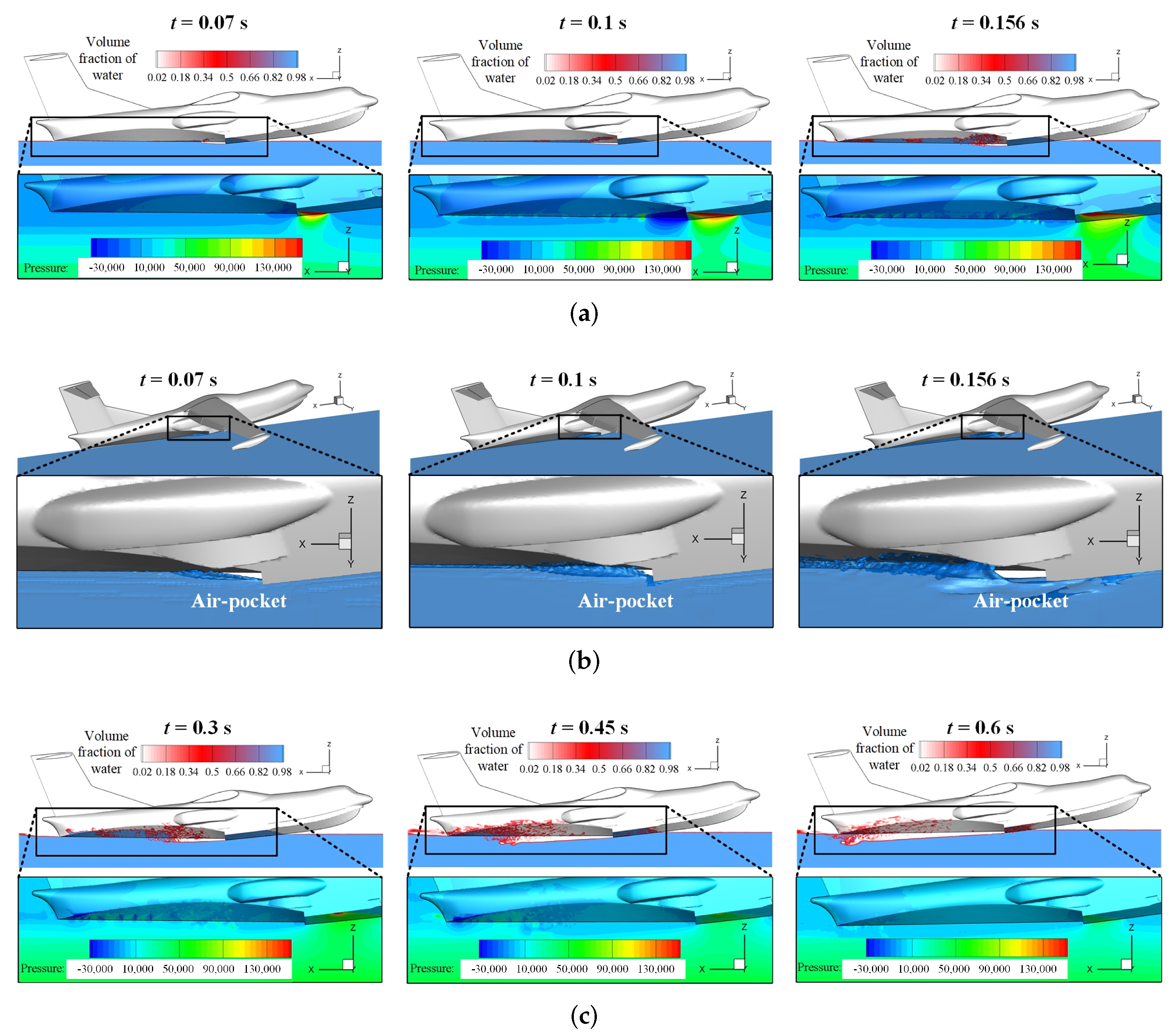
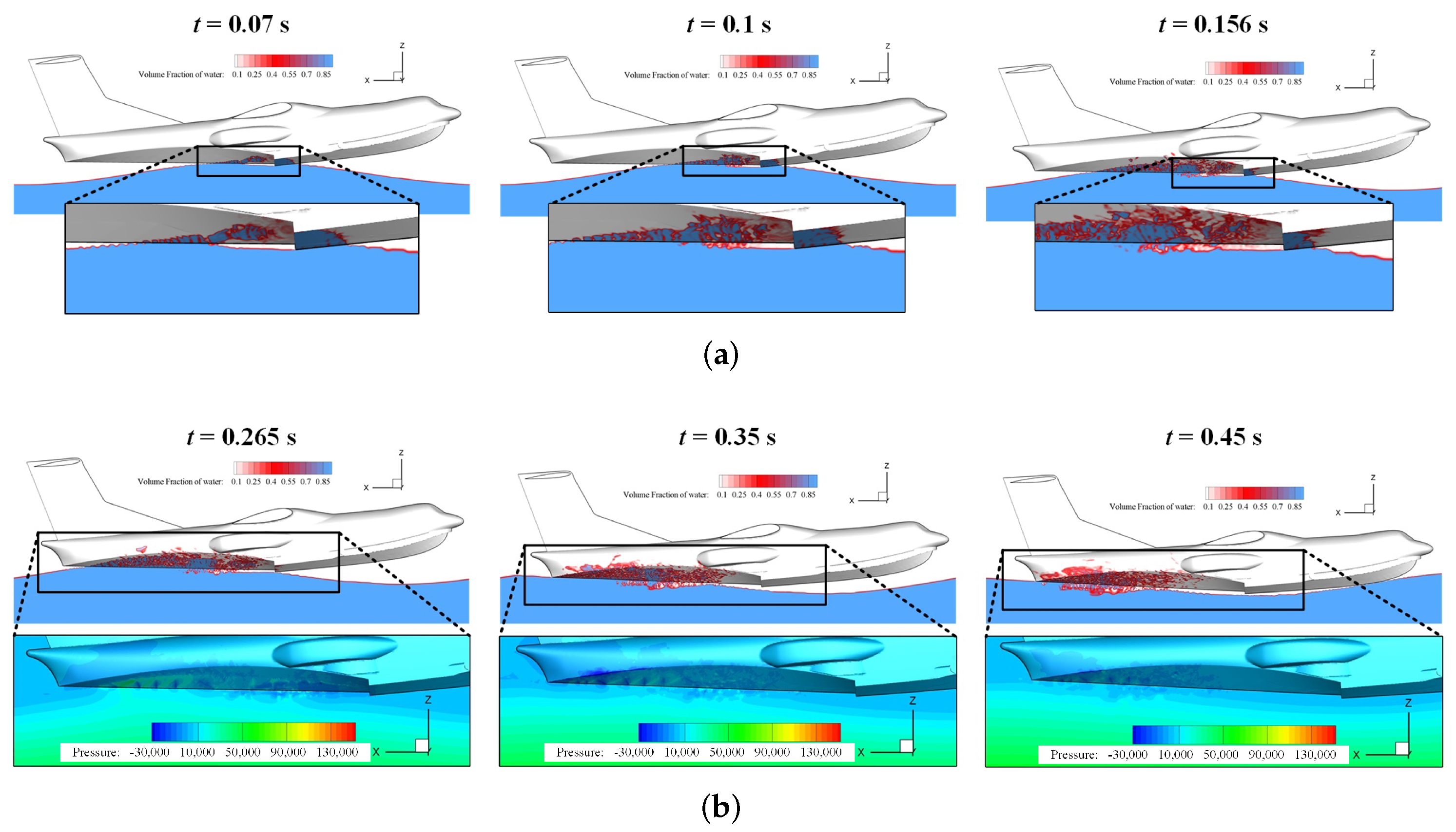
In the fuselage impacting stage of the calm-water-landing case, as shown in Figure 11a, the rear-fuselage, step and part of front-fuselage are impacting on the calm water surface. During this stage, the increment vertical and axis-x accelerations are mainly generated by the increase in impacting area of front-fuselage from t = 0.07 s to the time moment when the maximum acceleration occurs. Moreover, the peak pressure on the fuselage at the time of maximum vertical acceleration (approximately t = 0.1465 s) is about 250 kPa, which comparable with that in the rigid wedge vertical impact by Siemann and Groenenboom [43]. Therefore, the overload and movement of the aircraft are governed by the hydrodynamic force as evidenced in Figure 8e,f. As depicted in Figure 8d (red shaded region), the aircraft pitch angle slightly decreases due to that the high pressure area is near the center of gravity of the aircraft, thus the overpressure zone around the rear-fuselage leads to a pitch-down motion. Additionally, we notice that there is a negative pressure area near the step. This negative pressure is caused by the air-pocket phenomenon. Figure 11b presents the 3D view of free-surface evolution in which the zoom-in views clearly show that the air-pocket is formed by the water spray and step profile. As the air-pocket generated from t = 0.07 s to t = 0.1 s, the air-ventilation effect is weaken which results in a larger negative pressure region at the fuselage surface as shown in Figure 11a. After that, with the aircraft moving forward, the air suck-in tunnel is expanded and then leads to the reduction in negative pressure near the step region. This feature is exampled in the flowfield contours at t = 0.156 s. In the pitch-up stage of the calm-water-landing case, this air suck-in tunnel is further increased as demonstrated in Figure 11c, and the negative pressure near the rear-fuselage is formed which may be caused by the air-water mix effect. This negative pressure leads to a pitch-up motion as plotted in Figure 8d (red double-side arrow).
In the rear-fuselage impacting stage of the wave-crest landing case, the rear-fuselage and step are impacting on the wave surface. Figure 12a presents the air-water phase contour at the symmetrical plane in this stage. It shows that there is a dramatic air-water mix region behind the step. This region leads to the oscillation of accelerations as shown in Figure 8a,c. Moreover, by comparing the vertical and axis-x acceleration curves in these two figures during the second stage for the calm water and wave crest cases, it is found that the acceleration value of the wave-landing case is smaller than that of the calm-water-landing case. This is due to the wave surface shape leads to a small impacting area. Similarly, the wave surface shape also results in the reduction in impacting area of the step as shown in the zoom-in figures of Figure 12a. Consequently, the axis-x acceleration is reduced as reported in Figure 8c.
As the aircraft moving forward, the wave surface shape plays an even more important role in the front-fuselage on-flight stage. Figure 12b displays the air-water phase contour and zoom-in pressure distribution during this stage. It clearly demonstrates that the step and front-fuselage are on-flight because of the wave trough. Therefore, the overload of aircraft is mainly determined by the aerodynamics as illustrated in Figure 8e,f. We note that the aircraft experiences a pitch-down motion as plotted in Figure 8d. It may be caused by the pressure on the bottom surface of rear-fuselage. These phenomenons emphasize the necessity of air-water two-phase flows in the numerical studies of aircraft wave-landing event.

4.1.3. Pitch-Up Stage

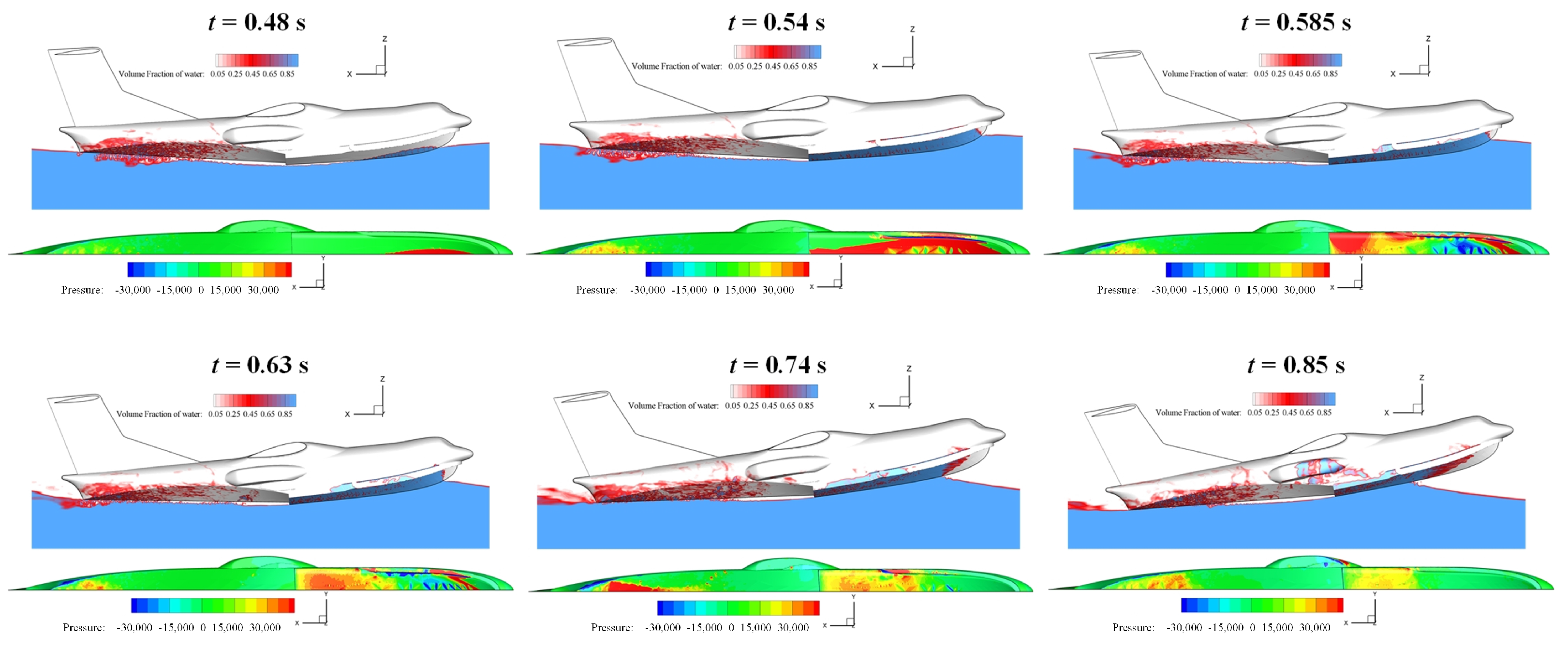
After the front-fuselage on-flight stage, the vertical velocity of the aircraft of wave-landing case is slightly larger than the initial vertical velocity as depicted in Figure 8b. Comparing with the fuselage impacting stage of the calm-water-landing case, the hydrodynamic load of second impacting and pitch-up stage of the wave-landing case is significantly larger as plotted in Figure 8a,c, which is caused by the larger impacting velocity and wave shape. A more comprehensive insight into the impacting load is obtained by comparing the impacting position and pressure distribution between Figure 11a and Figure 13. At t = 0.156 s, the moment of maximum load for calm-water-landing case, the pressure peak is located in the step region and the corresponding positive pressure area is small. In contrast, at t = 0.54 s, the time moment of maximum load in wave-landing case, the impacting load is mostly generated by the front-fuselage, as well as the entire second impacting stage. As a consequence, the pitch angle shown in Figure 8d is rising up. We also note that there are two acceleration peaks in Figure 8a,c at t = 0.54 s and t = 0.74 s, respectively. The mechanism behind these two peaks is probably contributed to the negative pressure on the front-fuselage. From t = 0.45–0.54 s, the front-fuselage heavily slams on the wave surface due to the large pitch angular acceleration generated by the rear-fuselage, and the impacting area gradually increases so that the accelerations quickly reach to the maximum. After that, during the time period of t = 0.54–0.63 s, the negative pressure takes place in the front-fuselage region and then disappears at the moment of the second peak. As indicated by the air-water phase contour at t = 0.74 s and t = 0.85 s in Figure 13, the area of the fuselage contacting with water shrinks when the aircraft moving forward and pitching up. Such a feature is relevant in the second decreasing of acceleration time–history, as well as the reduction in the growth rate of pitch angle.

4.2. Wave Height Effect

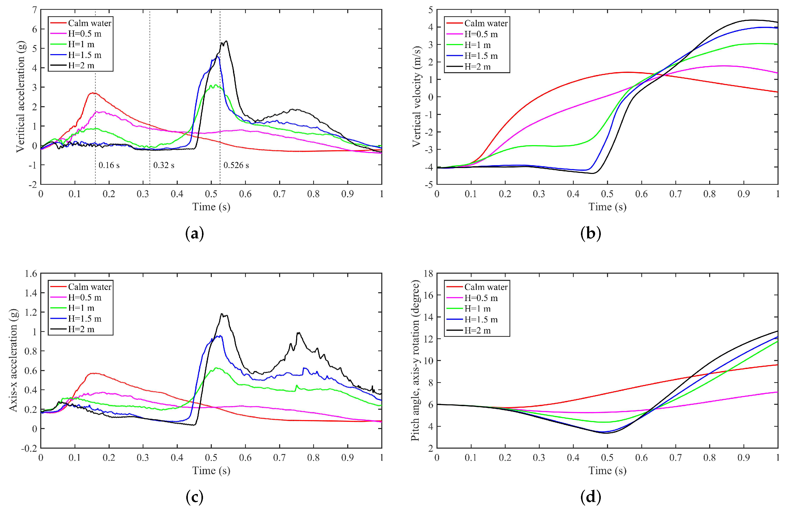
To study the wave height effect on the amphibious aircraft wave-crest-landing performance, five cases with the same wavelength of 40 m but different wave heights are compared. Figure 14 shows the numerical results in time. It can be seen that as the wave height increases from 0 (calm water) to 2 m with interval 0.5 m, the variations of accelerations, velocity and pitch angle of the aircraft have similar features in time. Before the aircraft impacts on the second wave, approximately t < 0.5 s, the aircraft landing performance is negatively correlated with the wave height. In contrast, the wave height positively influences the accelerations of the aircraft when t > 0.5 s. The general reason for these tendencies is the impact position between the free surface and the fuselage. The pressure distribution on the impact position is influenced by the wave height during the entire landing process. Consequently, it gradually changes the stages of the aircraft landing process from calm water-landing to wave-landing, i.e., fuselage impacting stage to rear-fuselage impacting and front-fuselage on-flight stages. Specifically, for the case of H = 0.5 m, the landing process is close to the calm water situation, except for a small increment of accelerations during t = 0.5–0.6 s as illustrated in Figure 14a,c. For the case of H = 1 m, the feature of landing performance combines the characteristic of calm water and wave landing situations, including fuselage impacting stage, front-fuselage on-flight stage and second impacting stage. As the wave height increased to 1.5 m, the stage of the landing process is exactly the same with the case of H = 2 m. To further explore the mechanisms of these phenomenons, three moments are selected based on the variation of vertical acceleration as illustrated in Figure 14a (black dashed line) and the corresponding contours of five cases are compared.
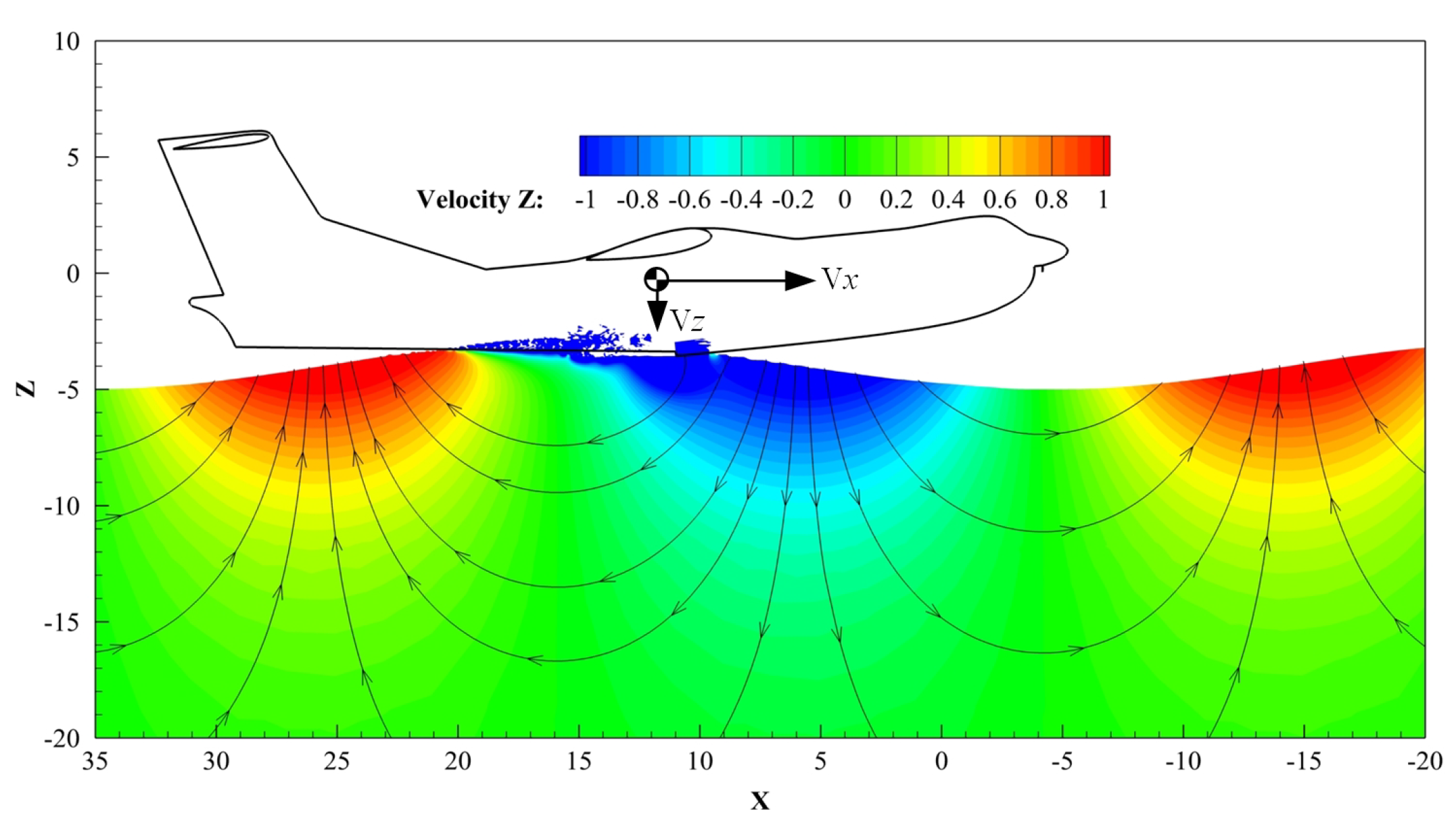
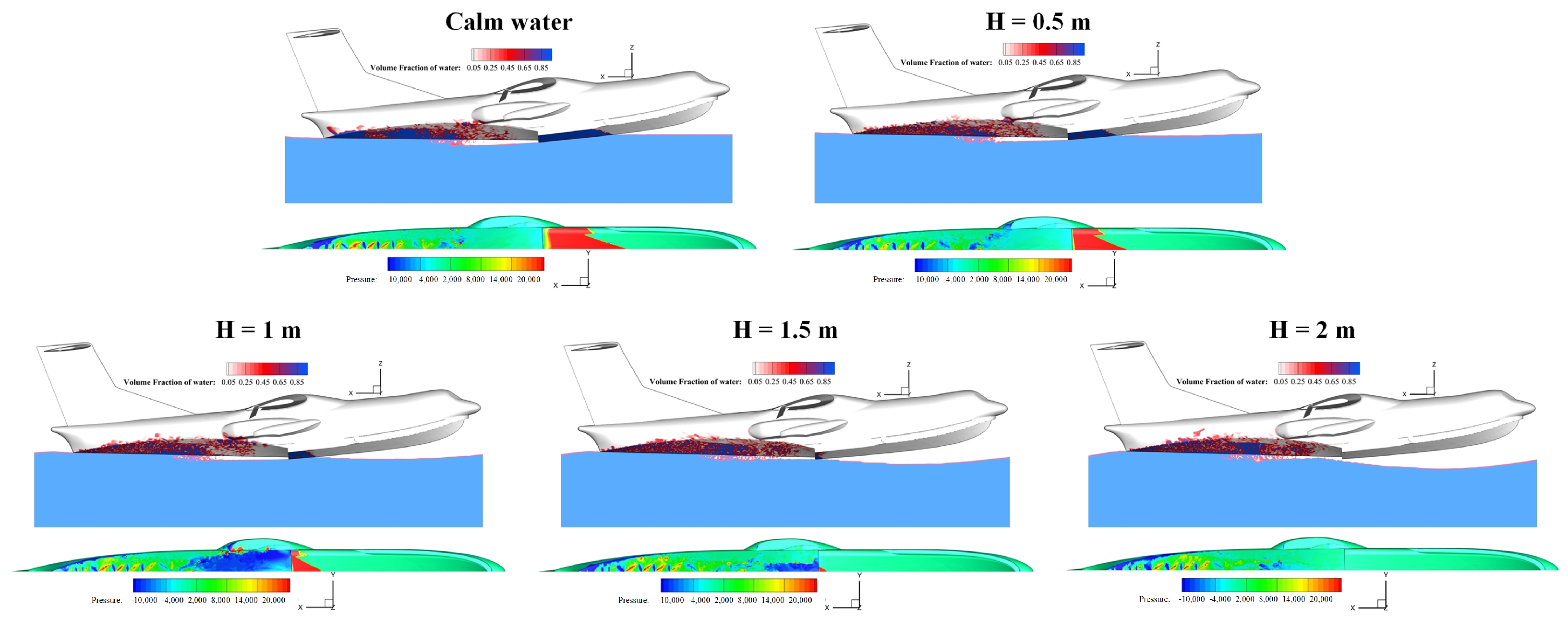
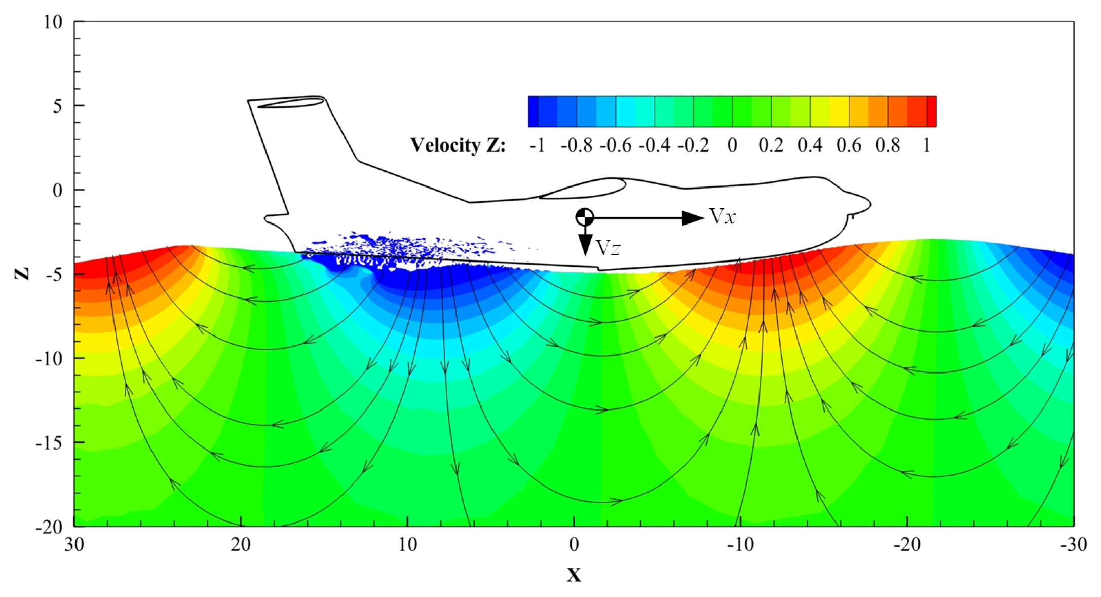
At t = 0.16 s, as plotted in Figure 14, the aircraft landing performance is negatively influenced by the wave height. Particularly, the acceleration of case H = 0.5 and 1 m is smaller than that of calm water case, and it drops to zero when the H increased to 1.5 and 2 m. These features are contributed by the wave surface slope and wave particle velocity. Figure 15 shows the comparison of flowfield of aircraft landing on wave surface with different wave heights at t = 0.16 s. Note that the air domain is blanked for better illustration. It can be seen that as the wave height increases, the wave surface becomes steeper and harder to be disturbed. Thus, when the step part of aircraft passed the crest position of first wave, the impacting/wetted area near the front-fuselage is reduced with the increment of the wave height. This is evidenced in the water phase contour in Figure 15. Another important factor is wave velocity. As shown in Figure 16, the vertical velocity of the wave field below the front-fuselage is negative and in the same direction as the vertical velocity of aircraft. It results in a reduction in the effective impacting velocity between the aircraft and free surface. In fact, the wave particle velocity is positively related to the wave height as demonstrated in Equation (6). Consequently, as evidenced in the pressure contour in Figure 15, the pressure on the fuselage decreases as the wave height increases.
As time forward, the effects of wave surface slope and wave particle velocity become more obvious. As shown in Figure 17, the impacting area near the front-fuselage and corresponding pressure decrease with the increment of the wave height. For the case of H = 1 , 1.5 and 2 m, the aircraft is almost on the front-fuselage on-flight stage at t = 0.32 s. In contrast, the aircraft landing performance in the case of H = 0.5 m is similar to the calm-water-landing case. This is because that the wave surface is easily disturbed with the small wave amplitude A = 0.25 m such that the front-fuselage always interacts with the water bulk during the whole landing process. Additionally, the duration of front-fuselage on-flight stage is negatively related to the wave height, as illustrated in Figure 14a. These features result in a pitch-down moment and smallest pitch angle in the case of H = 2 m as shown in Figure 14d.
After the front-fuselage on-flight stage, the front-fuselage of aircraft is heavily impacted on the wave surface as shown in Figure 18. As illustrated in Figure 14a,c, the vertical and horizontal loads of aircraft are positively affected by the wave height. Additionally, the second peak of acceleration in the case of H = 1 m is at the same level as the first peak of acceleration in the calm-water-landing case. The mechanisms of these tendencies can be summarized as two quantified factors, including pitch-down moment and effective vertical impacting velocity. As discussed before, the pitch-down moment is generated by the hydrodynamic load of the rear-fuselage and increases with the wave height. This feature is evidenced at t = 0.45 s in Figure 14d. A more influential factor is the vertical velocity of aircraft and wave field. As shown in Figure 14b, during the period of t = 0.2–0.5 s, the vertical velocity of aircraft in the case of calm water and H = 0.5 , 1 m is significantly smaller than that of the H = 1.5 , 2 m cases. The reason is that part of the kinetic energy of the aircraft is dissipated by the water bulk during t = 0.1–0.3 for the case of calm water and H = 0.5 , 1 m. Furthermore, the vertical wave particle velocity also contributes to the increase in the hydrodynamic load of aircraft. At the beginning of the second impacting stage, as exampled in Figure 19, the direction of vertical velocity of wave field below the front-fuselage is vertical-up. That results in an increment of effective vertical impacting velocity between the aircraft and free surface. As mentioned before, the wave velocity is monotonically controlled by the wave height. Thus, due to the combination of the vertical velocity of aircraft and wave particle velocity, the effective vertical impacting velocity of aircraft is proportional to the wave height during the second impacting stage.

5. Conclusions

The aircraft wave-landing performance is essentially different from the calm-water-landing situation. This paper studied the wave effect on the water-landing process of an amphibious aircraft. Several case studies are undertaken to evaluate the difference between calm water and regular wave and to explore the effect of wave height on regular wave-landing performance. The following conclusions can be drawn from the obtained results.
(1) In the aircraft regular wave-landing event, there are several distinctive features compared with the calm-water-landing case. First, a more rapid oscillation in aircraft overload time–history is presented due to the dramatic air-water mix in the rear-fuselage region. Second, the aircraft experienced three unique stages. In the rear-fuselage impacting and front-fuselage on-flight stages, because of the wave shape, the main part of the fuselage is not impacted on the wave surface. Therefore, the aircraft overloads are mainly determined by aerodynamic characteristics in these two stages. Third, the pitch-down angular acceleration generated by the rear-fuselage makes the front-fuselage of aircraft heavily slammed on the wave surface at beginning of the second impacting stage. That results in a large hydrodynamic impact load. Therefore, the maximum overload in this stage is obviously higher than that of the calm-water-landing case.
(2) The correlation between the acceleration of aircraft and the wave height is different in time and changes from negative to positive during the second impacting stage. Overall, as the wave height increases from 0.5 m to 2.0 m, the maximum acceleration of the aircraft increases. On the other hand, comparing with the calm-water-landing case, the safety of crews and aircraft structures is higher in the wave-landing situation when the wave height is less than 1.0 m. The reasons for these features are the wave surface slope and wave particle velocity. Generally, as the wave height increases with a fixed wave length, the wave steepness, wave slope and wave particle velocity both monotonously increase which could result in the variations of the impacting area and position of the aircraft and the effective impacting velocity between the aircraft and free surface.
Limited by the numerical simulation resource, the performance of the aircraft irregular wave-landing is not analyzed in the present study. In future studies, improvements will be made to the numerical simulation conditions, and the influence of significant height and mean period of the irregular wave on aircraft landing characteristics will be explored. Due to the temporal-spatial irregularity of wave surface, the aircraft irregular-wave landing process is more complicated thus the longer simulation time will be performed. Furthermore, the deformation of the fuselage in the air-water two-phase flows will be considered in the next step of this study.

Author Contributions

Conceptualization, methodology, formal analysis, investigation, visualization, writing—original draft preparation, J.C. and T.X.; software, validation, resources, data curation, M.W. and Y.L.; writing—review and editing, T.X. and M.T.; supervision, project administration, M.T. All authors have read and agreed to the published version of the manuscript.

Funding

This work was supported by the grants from Aeronautical Science Foundation of China (No. 20182352015 and 201928052009) and Nanjing University of Aeronautics and Astronautics (No. 180603DF01).

Institutional Review Board Statement

Not applicable.

Informed Consent Statement

Not applicable.

Data Availability Statement

The data presented in this study are available on request from the first author.

Acknowledgments

The authors would like to thank Nanjing Jiangbei New Area BPS (Biopharmaceutical Public Service Platform) HPC for the technical supports. The authors also thank Si Chen, Fan Liu, Yanghui Li, and Jiayi Li for the useful discussions.

Conflicts of Interest

The authors declare no conflict of interest.

Abbreviations

CFDComputational Fluid Dynamics
RANSReynolds-averaged Navier–Stokes
FVMFinite Volume Method
VOFVolume of Fluid
DFBIDynamic Fluid Body Interaction
Hwave height
Lwave length
Awave amplitude
kwave number
Twave period
dwater depth
L x , L y , L z computational domain size in the x, y, z directions
x , y , z computational cell size in the x, y, z directions
d t time step of numerical simulation

References

  1. Lindenau, O.; Rung, T. Review of Transport Aircraft Ditching accidents. In Proceedings of the 6th International KRASH Users’ Seminar (IKUS6), Stuttgart, Germany, 15–17 June 2009. [Google Scholar]
  2. Hughes, K.; Vignjevic, R.; Campbell, J.; De Vuyst, T.; Djordjevic, N.; Papagiannis, L. From aerospace to offshore: Bridging the numerical simulation gaps–Simulation advancements for fluid structure interaction problems. Int. J. Impact Eng. 2013, 61, 48–63. [Google Scholar] [CrossRef]
  3. Iafrati, A.; Grizzi, S.; Olivieri, F. Experimental Investigation of Fluid–Structure Interaction Phenomena during Aircraft Ditching. AIAA J. 2021, 59, 1561–1574. [Google Scholar] [CrossRef]
  4. Qu, Q.; Liu, C.; Liu, P.; Guo, B.; Agarwal, R.K. Numerical simulation of water-landing performance of a regional aircraft. J. Aircr. 2016, 53, 1680–1689. [Google Scholar] [CrossRef]
  5. Gretsch, J.; Henry, M.; Jivani, M.; Liwanag, M.; Rogers, A.; Smisko, A.; Wolf, D.; Siddens, A.; Satterwhite, M.; Bayandor, J. A Virtual Aerospace Crashworthiness Modeling Platform: Part I, Substantiation Water Ditching Trials. In Proceedings of the 50th AIAA Aerospace Sciences Meeting Including the New Horizons Forum and Aerospace Exposition, Nashville, TN, USA, 9–12 January 2012. [Google Scholar] [CrossRef]
  6. Coltman, J.W.; Arndt, S.M. The Naval Aircraft Crash Environment: Aircrew Survivability and Aircraft Structural Response; Technical Report TR-88490; Defense Technical Information Center: Fairfax, VA, USA, 1988.
  7. Authority, C.A. CAA PAPER 2005/06 Summary Report on Helicopter Ditching and Crashworthiness Research; Technical report; TSO: London, UK, 2005. [Google Scholar]
  8. Taber, M.; McCabe, J. An examination of survival rates based on external flotation devices: A helicopter ditching review from 1971 to 2005. SAFE J. 2007, 35, 1–6. [Google Scholar]
  9. Brooks, C.J.; MacDonald, C.V.; Donati, L.; Taber, M.J. Civilian helicopter accidents into water: Analysis of 46 cases, 1979–2006. Aviat. Space Environ. Med. 2008, 79, 935–940. [Google Scholar] [CrossRef]
  10. Brooks, C.J.; MacDonald, C.V.; Baker, S.P.; Shanahan, D.F.; Haaland, W.L. Helicopter crashes into water: Warning time, final position, and other factors affecting survival. Aviat. Space Environ. Med. 2014, 85, 440–444. [Google Scholar] [CrossRef]
  11. Seddon, C.M.; Moatamedi, M. Review of water entry with applications to aerospace structures. Int. J. Impact Eng. 2006, 32, 1045–1067. [Google Scholar] [CrossRef]
  12. Hughes, K.; Campbell, J. Helicopter crashworthiness: A chronological review of research related to water impact from 1982 to 2006. J. Am. Helicopter Soc. 2008, 53, 429–441. [Google Scholar] [CrossRef] [Green Version]
  13. Ortiz, R.; Portemont, G.; Charles, J.L.; Sobry, J.F. Assesment of explicit FE capabilities for full scale coupled fluid/structure aircraft ditching simulation. In Proceedings of the ICAS 2002 Congress, Toronto, ON, Canada, 8–13 September 2002. [Google Scholar]
  14. Pentecote, N.; Vigliotti, A. Crashworthiness of helicopters on water: Test and simulation of a full-scale WG30 impacting on water. Int. J. Crashworthiness 2006, 8, 559–572. [Google Scholar] [CrossRef]
  15. Jackson, K.E.; Fuchs, Y.T. Comparison of ALE and SPH simulations of vertical drop tests of a composite fuselage section into water. In Proceedings of the 10th International LS-DYNA Users Conference, Dearborn, MI, USA, 8–10 June 2008. [Google Scholar]
  16. Siemann, M.N.; Langrand, B. Coupled Fluid-Structure ComputationalMethods for AircraftDitching Simulation: Comparison ofALE-FE and SPH-FE Approaches. Comput. Struct. 2017, 188, 95–108. [Google Scholar] [CrossRef] [Green Version]
  17. Bisagni, C.; Pigazzini, M.S. Modelling strategies for numerical simulation of aircraft ditching. Int. J. Crashworthiness 2018, 23, 377–394. [Google Scholar] [CrossRef] [Green Version]
  18. Xiao, T.; Qin, N.; Lu, Z.; Sun, X.; Tong, M.; Wang, Z. Development of a smoothed particle hydrodynamics method and its application to aircraft ditching simulations. Aerosp. Sci. Technol. 2017, 66, 28–43. [Google Scholar] [CrossRef] [Green Version]
  19. Lu, Z.; Xiao, T.; Li, Z.; Zhang, Z.; Du, S.; Wang, Z. Pitching Angle on Space Capsule Water Landing Using Smooth Particle Hydrodynamic Method. J. Spacecr. Rocket. 2017, 54, 743–754. [Google Scholar] [CrossRef]
  20. Xiao, T.; Lu, Z.; Deng, S. Effect of Initial Pitching Angle on Helicopter Ditching Characteristics Using Smoothed-Particle-Hydrodynamics Method. J. Aircr. 2021, 58, 167–181. [Google Scholar] [CrossRef]
  21. Wick, A.; Zink, G.; Ruszkowski, R.; Shih, T. Computational simulation of an unmanned air vehicle impacting water. In Proceedings of the 45th AIAA Aerospace Sciences Meeting and Exhibit, Reno, NV, USA, 8–11 January 2007. [Google Scholar] [CrossRef] [Green Version]
  22. Streckwall, H.; Lindenau, O.; Bensch, L. Aircraft ditching: A free surface/free motion problem. Arch. Civ. Mech. Eng. 2007, 7, 177–190. [Google Scholar] [CrossRef]
  23. Guo, B.; Liu, P.; Qu, Q.; Wang, J. Effect of pitch angle on initial stage of a transport airplane ditching. Chin. J. Aeronaut. 2013, 26, 17–26. [Google Scholar] [CrossRef] [Green Version]
  24. Qu, Q.; Hu, M.; Guo, H.; Liu, P.; Agarwal, R.K. Study of ditching characteristics of transport aircraft by global moving mesh method. J. Aircr. 2015, 52, 1550–1558. [Google Scholar] [CrossRef]
  25. Woodgate, M.A.; Barakos, G.N.; Scrase, N.; Neville, T. Simulation of helicopter ditching using smoothed particle hydrodynamics. Aerosp. Sci. Technol. 2019, 85, 277–292. [Google Scholar] [CrossRef] [Green Version]
  26. Feng, S.; Mingzhen, W.; Jiaxu, Z.; Qi, H. Numerical Simulation Method for Wave Surface Landing of Seaplane. IOP Conf. Ser. Mater. Sci. Eng. 2020, 751, 012061. [Google Scholar] [CrossRef]
  27. Zhao, Y.; Qu, Q.; Liu, P. Numerical Study on the Extreme Impact Load of Wavy-Water Ditching. IOP Conf. Ser. Mater. Sci. Eng. 2020, 816, 012003. [Google Scholar] [CrossRef]
  28. Xiao, T.; Lu, Y.; Deng, S.; Zhi, H.; Zhu, Z.; Chen, J. Hydrodynamic Characteristics of a Helicopter Ditching on Different Positions of Wavy Water. J. Aircr. 2021, 58, 1094–1105. [Google Scholar] [CrossRef]
  29. Chen, C.; Sun, T.; Wei, Y.; Wang, C. Computational analysis of compressibility effects on cavity dynamics in high-speed water-entry. Int. J. Nav. Archit. Ocean. Eng. 2019, 11, 495–509. [Google Scholar] [CrossRef]
  30. Hirt, C.W.; Nichols, B.D. Volume of fluid (VOF) method for the dynamics of free boundaries. J. Comput. Phys. 1981, 39, 201–225. [Google Scholar] [CrossRef]
  31. CD-adapco, S. STAR CCM+ User Guide Version 12.04; CD-adapco: New York, NY, USA, 2017. [Google Scholar]
  32. Ohmori, T. Finite-volume simulation of flows about a ship in maneuvering motion. J. Mar. Sci. Technol. 1998, 3, 82–93. [Google Scholar] [CrossRef]
  33. Elhanafi, A.; Fleming, A.; Leong, Z.; Macfarlane, G. Effect of RANS-based turbulence models on nonlinear wave generation in a two-phase numerical wave tank. Prog. Comput. Fluid Dyn. 2017, 17, 141–158. [Google Scholar] [CrossRef]
  34. Craik, A.D. The origins of water wave theory. Annu. Rev. Fluid Mech. 2004, 36, 1–28. [Google Scholar] [CrossRef]
  35. Larsen, J.; Dancy, H. Open boundaries in short wave simulations—A new approach. Coast. Eng. 1983, 7, 285–297. [Google Scholar] [CrossRef] [Green Version]
  36. Choi, J.; Yoon, S.B. Numerical simulations using momentum source wave-maker applied to RANS equation model. Coast. Eng. 2009, 56, 1043–1060. [Google Scholar] [CrossRef]
  37. Peric, R.; Abdel-Maksoud, M. Reliable damping of free-surface waves in numerical simulations. Ship Technol. Res. 2016, 63, 1–13. [Google Scholar] [CrossRef] [Green Version]
  38. Massel, S.R. Ocean Waves Breaking and Marine Aerosol Fluxes; Chapter Wave Breaking Criteria and Probability of Breaking; Springer Science and Business Media: Berlin/Heidelberg, Germany, 2007; Volume 38, pp. 121–155. [Google Scholar]
  39. Dean, R.G.; Dalrymple, R.A. Water Wave Mechanics for Engineers and Scientists; World Scientific Publishing Company: Singapore, 1991; Volume 2, pp. 64–65. [Google Scholar]
  40. Jin, Y.; Zhi, H.; Lu, Y.; Wu, B.; Xiao, T.; Tong, M. Numerical Simulation of Three Dimensional Tank Impacting on Wavy Water. In Proceedings of the AIAA Aviation 2019 Forum, Dallas, TX, USA, 17–21 June 2019. [Google Scholar] [CrossRef]
  41. Lu, Y.; Xiao, T.; Chen, J.; Tong, M.; Liu, F.; Zhu, Z. Numerical Simulation of Helicopter Ditching on Wavy Water. In Proceedings of the AIAA Aviation 2019 Forum, Dallas, TX, USA, 17–21 June 2019. [Google Scholar] [CrossRef]
  42. Chen, J.; Xiao, T.; Shen, L.; Lu, Y.; Tong, M. Numerical Wave Simulation and Investigation of Air-wave-aircraft Interactions. In Proceedings of the AIAA Aviation 2019 Forum, Dallas, TX, USA, 17–21 June 2019. [Google Scholar] [CrossRef]
  43. Siemann, M.; Groenenboom, P. Pressure evaluation at arbitrary locations in SPH water impact simulations. In PARTICLES III: Proceedings of the III International Conference on Particle-Based Methods: Fundamentals and Applications: Stuttgart, Germany, 18–20 September 2013; CIMNE: Barcelona, Spain, 2013; pp. 961–974. [Google Scholar]
Figure 1. Computational case setup: (a) boundary condition; (b) simulation grid.
Applsci 12 02561 g001
Figure 2. Computational domain and initial flow field of aircraft water-landing simulation: (a) calm water-landing; (b) regular wave landing.
Applsci 12 02561 g002
Figure 3. Computational grid of regular and unidirectional wave cases: (a) domain grid and position of wave elevation probe; (b) local refined grid near the air-water interface, green surface and curve showing the desired wave.
Applsci 12 02561 g003
Figure 4. Comparison of 3D regular wave elevations in time: (a) probe P1 ( x = 0 m); (b) probe P2 ( x = 40 m); (c) probe P3 ( x = 80 m).
Applsci 12 02561 g004
Figure 5. Results of mesh dependency study: (a) vertical acceleration; (b) axis-x/horizontal acceleration.
Applsci 12 02561 g005
Figure 6. Results of time step dependency study: (a) vertical acceleration; (b) axis-x/horizontal acceleration.
Applsci 12 02561 g006
Figure 7. Computational global and zoom-in grid of the medium mesh, green curve represents the wave surface.
Applsci 12 02561 g007
Figure 8. Comparison of time–history results between calm water and wave crest aircraft landing simulation: (a) vertical acceleration; (b) vertical velocity; (c) axis-x acceleration; (d) axis-y rotation, pitch angle; (e) vertical acceleration by the hydrodynamics and aerodynamics; (f) axis-x acceleration by the hydrodynamics and aerodynamics.
Applsci 12 02561 g008
Figure 9. Comparison of transient snapshots ( t = 0 , 0.5 and 1.0 s) of whole computational domain movement, free surface evolution and mesh around the aircraft model: (a) calm water-landing; (b) wave crest landing. The rectangular box is the computation domain; blue line and surface are the air-water interface; all snapshots are in the same ground-fixed coordinate XYZ with same views.
Applsci 12 02561 g009
Figure 10. Comparison of aircraft landing in calm water and wave crest during the step impacting stage.
Applsci 12 02561 g010
Figure 11. Time-snapshots of flowfield of aircraft landing in calm water: (a) air-water phase contour and pressure distribution during the impacting stage; (b) 3D view of free-surface evolution during the fuselage impacting stage; (c) air-water phase contour and pressure distribution during the pitch-up stage.
Applsci 12 02561 g011
Figure 12. Time-snapshots of flowfield of aircraft landing in wave field at crest position: (a) air-water phase contour during the rear-fuselage impacting stage; (b) air-water phase contour and pressure distribution during the front-fuselage on-flight stage.
Applsci 12 02561 g012
Figure 13. Time-snapshots of flowfield of aircraft landing in wave field during the second impacting and pitch-up stage: the first and third lines are air-water phase contours; the second and fourth lines are corresponding pressure distributions at bottom surface of fuselage.
Applsci 12 02561 g013
Figure 14. Comparison of time–history results of aircraft wave-landing with different wave lengths: (a) vertical acceleration; (b) vertical velocity; (c) axis-x acceleration; (d) axis-y rotation, pitch angle.
Applsci 12 02561 g014
Figure 15. Comparison of free surface and pressure distribution of aircraft landing with different wave heights at t = 0.16 s.
Applsci 12 02561 g015
Figure 16. Vertical wave velocity of water field when aircraft landing on wave surface with H = 2 m at t = 0.16 s.
Applsci 12 02561 g016
Figure 17. Comparison of free surface and pressure distribution of aircraft landing with different wave heights at t = 0.32 s.
Applsci 12 02561 g017
Figure 18. Comparison of free surface and pressure distribution of aircraft landing with different wave heights at t = 0.526 s.
Applsci 12 02561 g018
Figure 19. Vertical wave velocity of water field when aircraft landing on wave surface with H = 2 m at t = 0.45 s.
Applsci 12 02561 g019
Table 1. Mesh convergence study.
Grid Resolution Δ x, mm Δ y, mm Δ z, mmTotal Cell Number, Million
Coarse100010001008.8
Medium5005005018.4
Fine2502502528.7
Table 2. Time step size convergence study.
Mesh Δ t, sCourant Number
Medium 1 × 10 4 0.1284
Medium 2 × 10 4 0.2562
Medium 5 × 10 4 0.6425
Publisher’s Note: MDPI stays neutral with regard to jurisdictional claims in published maps and institutional affiliations.