1. Introduction
Bistable micro and nanostructures such as initially curved beams, plates, or spherical caps manifest several unique features making them attractive for implementation in micro-and nanoelectromechanical systems (MEMS/NEMS). When subject to a quasi-statically increasing loading, these devices manifest abrupt, commonly referred as a snap-through (ST), transition between two different stable configurations once the loads exceed a certain critical ST value. The decrease of the force below another, snap-back (SB) or release (R), critical value is followed by the snapping of the device back to its first, associated with the smaller deflection, stable configuration.The intrinsic hysteresis of the loading–unloading cycle (since SB and ST forces and deflections are different) is exploited in electrical and optical switches, micro- and nanomechanical nonvolatile memories, or MEMS/NEMS logic elements [
1,
2,
3]. The bistable devices, which manifest latching and are locked in the switched position at zero loading and therefore zero power, are especially suitable for implementation in autonomous systems and attract significant interest [
4,
5,
6]. Since the ST or SB transitions are followed by the high-frequency vibrations of the structure, bistable devices are implemented in energy harvesters for the conversion of the low-frequency aperiodic inertial inputs into oscillatory outputs at a higher, well-defined, frequency [
7]. In the sensors arena, the extremely high sensitivity of the bistable devices in the vicinity of the critical ST and SB configurations lies in the foundations of threshold accelerometers, inertial switches, gas, pressure, and flow sensors [
1,
2,
8,
9,
10], as well as event-based wake-up sensors for Internet of Things (IoT) applications [
11,
12]. Wideband natural frequencies tunability of bistable devices in the configurations close to the ST or SB points is exploit to increase the sensitivity of resonant sensors [
13,
14].
It should be noted that the behavior of conventional macro-scale structures prone to snap-through buckling is a long-standing topic in structural mechanics [
15,
16,
17]. In these structures, the appearance of bistability is related to the geometric nonlinearities or/and the nonlinear material behavior. What distinguishes micro- and nanodevices is that they require actuation and, as a result, are loaded by forces of a non-mechanical nature, such as magnetic [
18] or (the most widely used) electrostatic. The intrinsic nonlinearities of these forces may result in additional instabilities not observed in the structures loaded by prescribed, configuration-independent, forces. For example, devices actuated by electrostatic forces are prone to the so-called pull-in (PI) instability when the deformable element collapses toward the actuating electrode at the operating voltage above a certain critical value. The combination of nonlinearities associated with the electrostatic forces with the geometric nonlinearities of the bistable structures may result in more rich behaviors and open new possibilities for the designers of microsensors. Among electrostatically actuated bistable structures, double-clamped initially curved beams (arches) operated by a gap-closing electrode are the most intensively researched. The beam-type devices are distinguished by simplicity, robustness, manufacturability, small footprint, and the ability to be downscaled to a nanosize. Many interesting effects such as consecutive ST and PI instabilities, [
19,
20], symmetry breaking, multistability [
21], high-frequency tunability, veering, and internal and parametric resonances [
22,
23,
24] were reported, just to name a few. Much less attention was paid to the two- and three-dimensional micro-scale structures, such as plates or shells operated by electrostatic forces. Initially flat plates were considered by several authors [
25,
26,
27], and pull-in behavior and nonlinear resonant responses were investigated both theoretically and experimentally. The frequency tunability of the flat or imperfect plates operated by gap-closing electrodes was studied as well [
28]. The natural frequencies and mode shapes of initially flat circular and rectangular micro-plates around electrostatically induced deformed equilibrium positions were studied in [
23,
26,
29]. The influence of physical stimuli such as temperature, pressure, and various phenomena typical to systems of micro- and nanoscales, including Casimir and van der Waals force, along with the size effect, were also investigated [
30,
31,
32]. The static and dynamic behavior of electrostatically actuated nanoscale structures made of 2D materials, such as graphene or molybdenum disulfide, attracted significant attention from researchers during the last decade [
33]. In all these works, the plates were initially flat or of a small, caused by an initial imperfection, curvature, which is not sufficient for bistability.
It is not unfounded to expect that electrostatically actuated bistable microplates and shallow microshells may exhibit advantages similar to those of curved beams. However, the works devoted to these structures are sparse. These include the investigations of the static and dynamic behaviors of slightly curved and imperfect microplates by studies [
34,
35], which were formulated in the framework of couple-stress theory and studies where electrostatic actuation was taken into account [
28,
36,
37]. Initially flat plates pre-loaded by a uniform constant pressure and then loaded by the nonlinear electrostatic force were shown to be bistable in studies [
38,
39]. The bistability of the pressurized graphene membrane was investigated in studies [
39,
40]. The bistable behavior of electrostatically actuated initially curved circular plates was recently investigated theoretically [
6] and later demonstrated experimentally [
41]. The theoretical analysis, in the framework of the Föppl von Kármán plate theory, was based on a reduced-order model built using the Galerkin method. The experiments were carried out using bell-shaped shallow shells, fabricated by a novel self-molding soft punch stamping approach. Note that while the implementation of microshells in MEMS/NEMS-resonant sensors has been demonstrated [
42,
43,
44], the fabrication of micro- and nanoscale three-dimensional thin-walled structures is still a challenge.
In the present work, we explore the spectral behavior of initially curved circular bistable microplates, actuated by a nonlinear configuration-dependent distributed electrostatic force provided by a gap-closing electrode. The main focus is on the investigation of the frequencies and associated modes of the free undamped vibrations of the plate around the deformed equilibria of the structure, dictated by the electrostatic force. The vibrations around the configurations corresponding to the voltages lower than the ST values (the first stable branch), as well as post-buckled equilibrium states (the second stable branch), are considered. In contrast to the previously considered devices of this type, the plate analyzed here is bell-shaped in its initial, stress-free, configuration and is also sufficiently curved as to be bistable. The choice of the initial geometry of the structure and its dimensions is motivated by, and is consistent with, the actually fabricated devices previously reported by us [
41]. We show that in the bell-shaped plates, the vibrational modes may differ significantly from those of the initially flat or slightly curved imperfect plates, or of the shallow spherical caps. The motivation of the work is two-fold. From one side, understanding of the role of the initial curvature and of the (electrostatic) pre-loading on the natural frequencies and modes of the plate, along with the evaluation of the appropriate geometrical and operational parameters required to achieve the desired response, is a necessary prerequisite for the implementation of bistable microplates in sensors. From another side, knowledge of the plate spectral content is necessary for the construction of compact yet reliable approximate RO models, which use the vibrational modes as the base functions.
In the next section, the equations governing the axisymmetric behavior of a bell-shaped curved plate are derived based on the Föppl von Kármán plate theory. To obtain the solution, a reduced-order model based on the Galerkin decomposition is built. While the nonlinear static version of the equations is employed for defining the plate equilibrium state under an applied tuning load, the eigenvalue problem resulting from the linearization of the equations around the static equilibrium is solved for the natural frequencies and modes. The results of the RO model are compared with results of an FE analysis for the cases of a curved plate with and without a transverse uniformly distributed mechanical load. The FE solution of the coupled electromechanical static problem for the electrostatically actuated plate is presented up to the snap-through, and then compared with the RO model. The latter is then employed for investigating the effect of the electrostatic load on the spectral response, illustrating the feasibility of the electrostatic modulation of the plate stiffness and accompanied resonance frequencies and modes. Finally, the role of the base functions choice on the RO model quality is investigated. The simplest single-degree-of-freedom (DOF) RO model with the numerically obtained fundamental mode of a curved plate serving as the base function is shown to provide better accuracy than the five DOF model with the flat plate modes as the base functions.
2. Materials and Methods
We consider an initially curved bell-shaped circular plate clamped at its outer circumference (
Figure 1). The plate is assumed to be made of homogeneous isotropic linearly elastic material, with Young modulus
E and Poisson ratio
. The thickness
of the plate is assumed to be small compared to the plate radius
R. The initial shape of the plate is described by the function
, where
is the elevation of the plate central point above its clamped edge and
is a non-dimensional function such that
. Since the device is assumed to be fabricated by the self-molding stamping approach [
41], the plate is assumed to be bell-shaped and stress-free in the initial as-fabricated configuration. The plate is actuated by a transverse-distributed electrostatic force (electrostatic pressure) generated by a gap-closing flat electrode spanning the entire plate area and located at a distance
from the plate outer boundary.
The plate is considered in the framework of the Kirchoff hypothesis combined with the nonlinear Föppl von Kármán shallow plate theory; the in-plane inertia is neglected. The axisymmetric motion of the plate is described by the following system of coupled non-dimensional nonlinear partial differential equations [
45], completed by the clamped boundary conditions
Here
is the non-dimensional radial displacement and
is the non-dimensional location (
z coordinate) of the plate above its outer clamped boundary. The non-dimensional electrostatic force is described using the simplest parallel capacitor formula such that
, where
is the voltage parameter. In the case of actuation by a prescribed mechanical, configuration-independent, force,
f is replaced by the mechanical load parameter
. The non-dimensional parameters used in the development are defined in (
Table 1), where
is the bending stiffness,
is the permittivity of vacuum, and
V is the voltage difference between the plate and the electrode.
To investigate the small-amplitude undamped vibrations of the plate around an equilibrium corresponding to a specific transverse load, the radial displacement
u and the elevation
w are decomposed into the static and the dynamic parts
The static part of the response is governed by the nonlinear equilibrium equations, namely Equation (
1) and the static counterpart of Equation (
2), with
u and
w replaced by
and
, respectively,
and with the force parameter
f suitably adapted for the specific loading case, either mechanical or electrostatic.
The notations,
are, respectively, the time-dependent (dynamic) radial and transverse displacements with respect to the equilibrium (
Figure 2). The equations governing the small free vibrations around the forced static equilibrium are obtained by linearizing Equations (
1) and (
2) around the equilibrium configuration associated with the deflections
,
Here,
for the case of the mechanical loading and
in the case of the electrostatic loading. Equations (
6) and (
7) were used for the calculations of the natural modes and frequencies of the plate around the deformed equilibrium.
2.1. Reduced-Order Model
To analyze the plate modal behavior, the RO model of the plate is built using the Galerkin decomposition. The non-dimensional static and dynamic components of the response are approximated by the series
where
,
is the mode/DOF number,
is the non-dimensional frequency,
,
are the generalized coordinates of the static radial deflection and elevation, respectively, and
,
are the corresponding dynamic counterparts. Note that the harmonic time-dependence in Equation (
9) is directly introduced since the dynamic Equations (
6) and (
7) are linear and separation between the spatial and time variables is possible.
The base functions
and
are the eigenmodes of a flat circular clamped plate [
46,
47], namely
Here,
and
are, respectively, the Bessel and the modified Bessel functions of order
m,
and
are constants, which are chosen such that
,
. The eigenvalues for transverse vibrations,
, and the in-plane eigenvalues,
, are the solutions of the following characteristic equations
In the present work, we consider only the axisymmetric vibrations of the plate and set
. Moreover, the initial shape of the plate is assumed to be in the form of the fundamental symmetric mode of a flat plate, namely
where
.
2.1.1. Equilibrium
Substituting Equation (
8) into Equations (
4) and (
5), taking into account Equations (
10)–(
12) and implementing the usual Galerkin procedure, we obtain the system of 2
N coupled nonlinear algebraic equations in terms of the generalized coordinates
,
(see study [
5] for the static ROM with the flat plate buckling modes serving as base functions)
Here
represent the elements of the vectors of the generalized electrostatic and mechanical forces, respectively.
2.1.2. Free Vibrations
For the spectral response, the representation of Equations (
8) and (
9) with the base functions given by Equation (
10) and the initial shape given by Equation (
12) were substituted into Equations (
6) and (
7). The Galerkin procedure results in the following linear algebraic eigenvalue problem in terms of the generalized vibrational amplitudes
Equations (
16) and (
17) allow finding the approximation the frequencies and the modes of the free undamped vibrations of the plate around the stable equilibria. Note that while the eigenvalue problem itself, Equations (
16) and (
17), is linear, the associated static problem, which should be solved to find the equilibrium configuration, is nonlinear. Namely, the eigenvalues and eigenvectors of Equations (
16) and (
17) depend on the (parameterized by the voltage parameter
) equilibrium values of the generalized coordinates
, which are found numerically using Maple software, as the solutions of the system of nonlinear algebraic Equations (
13) and (
14). To track unstable branches of the equilibrium curves, arc-length continuation (the Ricks method) was implemented, as detailed in study [
5]. The obtained static deflections
are then used to calculate the coefficients (the stiffness and mass matrices) of the dynamic equations Equations (
16) and (
17). The eigenvalues and the eigenvectors of Equations (
16) and (
17) are then found numerically using an eigenvalue problem solver in Matlab.
3. Results and Discussion
In all the calculations, plates with a radius of
m, thickness of 400 nm, and initial elevation-to-thickness ratio varying from 0 to 30, were considered. This specific geometry was adopted since plates of the same dimensions were previously fabricated using the mold-less stamping technique and their bistable behavior was demonstrated theoretically and in the experiment [
41].
Prior to using the ROM for the vibration analysis of the plate, the ROM was verified by comparing its results with those provided by the finite elements (FE) simulation carried out using Ansys package. In the case of mechanical loading, shell elements SHELL181 with four nodes and quadratic interpolation were used in the three-dimensional FE model of the device. To track the unstable branches of the equilibrium curves, arc-length continuation implemented in Ansys was used in the case of mechanical loading. In the coupled electromechanical analysis of an electrostatically loaded structure, PLANE223 elements with eight nodes were used for the air–electrostatic domain between the plate and the electrode. The plate itself was meshed using PLANE183 elements with eight nodes. The plate thickness was subdivided into four layers while the air gap was constructed as a single layer to avoid mesh distortion. Electrostatic boundary conditions included prescribed voltages on the top and bottom surfaces of the air gap. Several mesh refinements were carried out in both mechanical and coupled electromechanical FE simulations to reach convergence with the relative error of less than 0.1% in terms of the fundamental mode frequency. Consequently, 67,840 elements and 68,137 nodes were used for the mechanical simulations. The coupled electromechanical FE model consisted of 5000 elements and 19,012 nodes. In all the cases, both RO and FE models incorporated the leading-order geometric nonlinearities of the plate and, as a result, the key features of the response, including von Kármán stiffening/softening and bistability.
3.1. Quasi-Static Mechanical Response
In a previous investigation of the bistable quasi-static behavior of shallow-curved plates under mechanical and electrostatic transverse loads (see study [
5]), it was concluded that at least three DOF of a Galerkin ROM are required for an adequate estimation of the snap-through limit point location and force. However, this study used buckling modes of a flat circular plate as base functions. To determine the number of DOF required for a converged equilibrium with the present ROM, the response of the plate to mechanical load was obtained by solving Equations (
13) and (
14) with
, for various numbers of DOF. The FE results were used as a reference. The errors of the ROM predictions are presented in
Figure 3, which indicates that converged snap-through limit point location and force can be calculated with satisfactory accuracy using seven DOF. Thus, further results in the present work were obtained by using the seven DOF ROM for the approximation of both the static and free vibration problem solutions.
3.2. Eigenvalue Analysis
The fundamental mode profile and its variation with the increasing initial elevation-to-thickness ratio is presented in
Figure 4, which shows the normalized displacements
and
from the equilibrium state (rather than the full elevation
and
(see
Figure 2). The results indicate that the fundamental mode profile is strongly affected by the plate’s initial curvature, quantified by the center point initial elevation,
. The fundamental out-of-plane mode-displacement profile is similar to that of the initially flat plate only for slightly curved plates with an elevation-to-thickness ratio smaller than
. For the plates of a higher curvature, the fundamental mode shapes strongly deviate from that of a flat circular plate. FE maps of the first three axisymmetric modes for plates of various values of the elevation-to-thickness ratio
are depicted in
Figure 5. In the examined examples, the third axisymmetric mode is less sensitive to the effect of the initial curvature.
The linear eigenvalue analysis based on the ROM is carried out by solving the eigenvalue problem (Equations (
16) and (
17)) with
, zero static axial deflection
, and static elevation, which equals the initial as-fabricated plate profile,
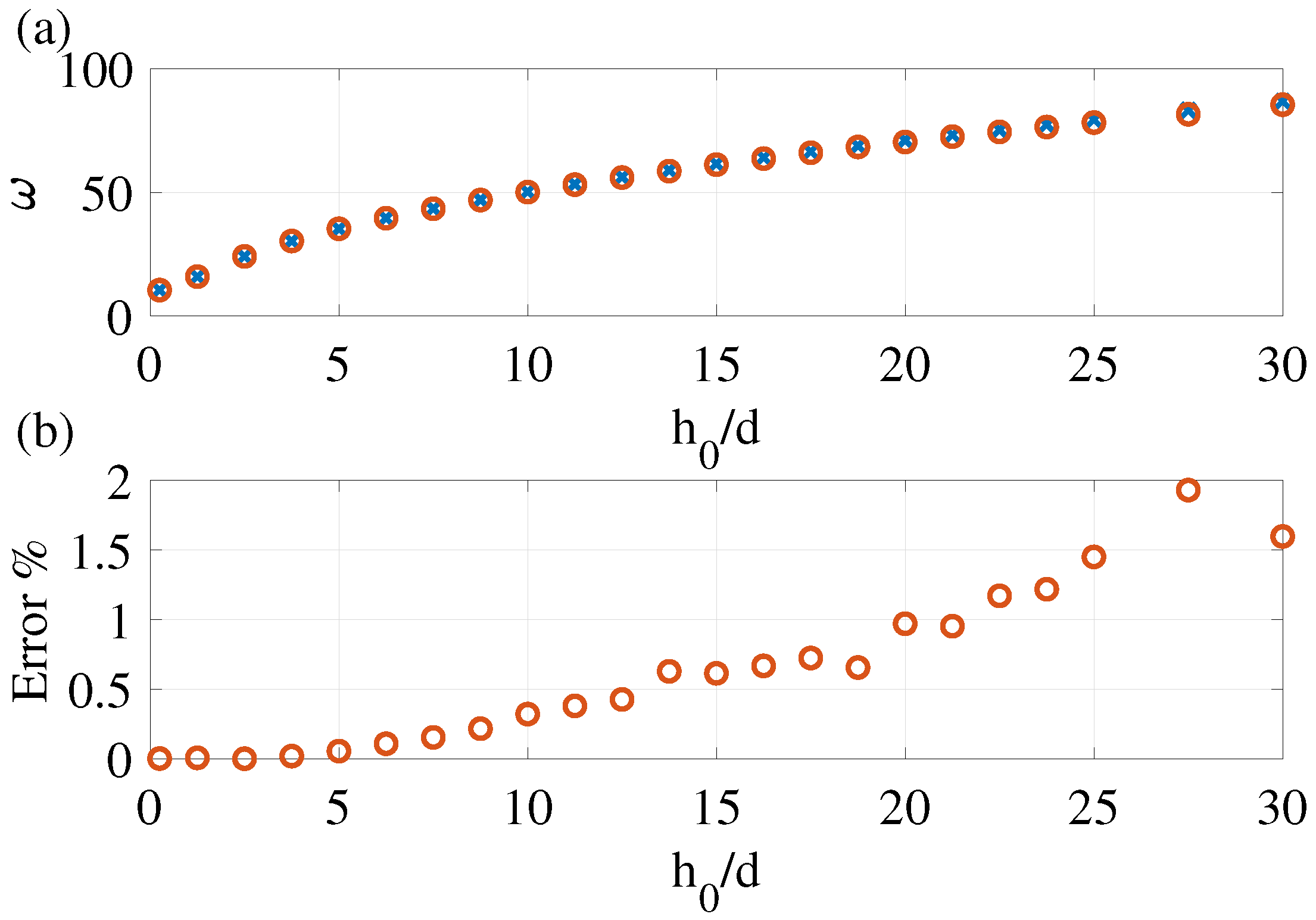
. The latter results, in the form of the fundamental frequency,
, versus the initial elevation-to-thickness ratio, are presented in
Figure 6, together with the reference eigenfrequencies obtained by the FE analysis (purple × markers). In accordance with the corresponding error analysis (shown in the inset), the three DOF ROM predict the frequency of the fundamental vibration mode with an error of
for the plate’s elevation-to-thickness ratio of up to
. Higher elevation-to-thickness ratios require the use of at least five DOF to achieve an accuracy of less than
, while errors of less than
are achieved with ten DOF. The results for the number of DOF between six and nine are not presented in the figure and fall between those obtained for the five and 10 DOF models. The higher required number of DOF for more curved plates can be attributed to the fact that, as the plate curvature increases, its fundamental mode deviates more significantly from that of a flat plate.
3.3. Frequency Tuning
3.3.1. Mechanical Tuning
The equilibrium curves of a mechanically loaded curved plate with
and a gap of
m obtained using the seven DOF ROM and the FEM are presented in
Figure 7. The fundamental modes of vibrations around differing equilibrium states along the equilibrium path, under various magnitudes of the mechanical loading, are presented in the insets. Good agreement between the ROM and FEM predictions, for both the equilibrium path and the tuned fundamental modes, is observed. This agreement is further demonstrated in
Figure 8, where the ROM and the FEM predictions for the mechanically tuned real parts of the eigenvalues associated with the first five axisymmetric modes of the plate are presented. As expected, the fundamental mode frequency becomes zero at the snap-through (ST) and release (R) limit points. Non-zero imaginary parts of the eigenvalues (not shown) obtained within the interval between the ST and the R points (vertical black dashed lines) indicate that plate equilibria are unstable in this interval of the deflections.
3.3.2. Electrostatic Tuning
In addition to the analysis of the frequency tuning by the mechanical load (
Section 3.3.1), electrostatic frequency tuning was studied. The static FE analysis up to the first limit point (ST) was first carried out, followed by the eigenvalue analysis. The equilibrium curve of the electrostatically loaded plate is presented in
Figure 9. In this case, similarly to the case of mechanical loading, good agreement between the ROM and FEM predictions is observed for both the equilibrium path (
Figure 9) and the tuned fundamental modes (
Figure 10).
The effect of the (time-independent) electrostatic force on the fundamental mode frequencies of the curved plates of various initial elevation-to-thickness ratios are presented in
Figure 11 in their non-dimensional and dimensional forms. The latter clearly reveals that an increased curvature results in an increased stiffness, higher initial frequency, and in a wider frequencies tuning range. As the voltage increases, the stiffness is diminished in a somewhat similar way in all the bistable curved plates, due to the reduction of curvature and the accompanying increase of the in-plane stresses. The sensitivity to the electrostatic loading associated with the voltage change dramatically increases upon approaching the snap-through limit point.
To demonstrate the influence of the electrostatic force nonlinearity, in addition to the geometric mechanical nonlinearity of the plate, on the frequency tuning, the sensitivity of the electrostatically and mechanically actuated plates are compared in
Figure 12. Tuning by forces below the critical ST value is examined. The results show that for the realistic initial distances between the electrode and the plate the influence of the electrostatic nonlinearity on the frequency tuning is minor. Consequently, the simpler analysis of the plate mechanically loaded by a uniform pressure can be used to predict frequency tuning also of the electrostatically actuated curved microplates.
3.4. Curved Plate Vibrational Modes as Base Functions
In the previous sections, it was found that the curved plate vibrational modes are significantly different from those of a flat plate. As a result, more than five DOF were needed in order to obtain an accuracy of less than
of the ROM analysis, employing the vibrational modes of initially flat plate as base functions. Here, we show that the efficiency of the ROM can be improved by utilizing the vibrational modes of curved plates as base functions. As a primary demonstration of this option, we obtain the fundamental mode frequency of the unloaded plate using the single DOF RO model. To this end, the free vibrations (Equations (
16) and (
17)) are modified as follows. The static in-plane deflection is set to zero, and out-of-plane deflection is taken to be equal the initial elevation of the unloaded plate, i.e.,
. Recall that in Equations (
16) and (
17), both the initial elevation, Equation (
12), and the dynamic out-of-plane displacements were represented using the out-of-plane modes
of a flat plate. Since now the initial shape and the deflection are represented by different functions, to avoid confusion,
in the notation for the initial shape was replaced by
, such that
.
The mode shapes
and
are obtained by fitting the FE solution. Ten Bessel and modified Bessel functions are used as the fitting functions. As expected, the solution of Equations (
18) and (
19) for each elevation are in good agreement with the FE fundamental mode frequency. The discrepancy between the two increases with the elevation due to lower fit accuracy mainly in the center and at the edge. The error is less than
, even at a large elevation of
, (
Figure 13).
4. Conclusions
In this work, we analyze the free vibrations of initially curved bistable bell-shaped circular microplates around the equilibrium states. The initial bell-shaped profile of the plate is chosen since this is the shape that comes out as a result of the mold-less stamping fabrication method suggested in study [
41]. The plates are loaded either by uniform pressure or by nonlinear deflection-dependent electrostatic force. The multi-DOF reduced-order model of the structure, which is described in the framework of the Föppl von Kármán shallow plate theory, is built and verified using the FE analysis. The RO model is then used to describe the static responses of the plates to the quasi-static loading and then to obtain the frequencies and modes of the free vibrations of the mechanically and electrostatically actuated plates around the equilibrium configurations.
Several aspects of the work’s contribution can be mentioned. First, we found that the modal shapes of even slightly curved bell-shaped plates differ significantly from that of the initially flat plate. Specifically, the fundamental mode of the curved plate has an annular rather than bell-shaped profile and resembles one of the higher axisymmetric modes of the flat plate. We attribute this result to the fact that the Gaussian curvature of the (axisymmetric) bell-shaped plate changes its sign along the radius of the plate. In the vicinity of the zero Gaussian curvature circular line (the inflection point of the plate initial shape profile),
Figure 2 shows that the stiffness of the shell is reduced, which may result in higher modal deflections [
48]. We also show that the readily available vibrational modes of the initially flat plates can be reliably used as the base functions for the analysis of shallow-curved plates by means of the ROM. In this context, knowledge of the vibrational mode shapes for the curved plate could be useful for the coarse estimation of the required number of DOF in the RO models exploiting the modes of the flat plate. For example, the fact that the fundamental mode of the slightly curved plate looks similar to the third mode of the flat plate is a clear indication that the single DOF ROM incorporating flat plate modes as the base functions will be not sufficient, and that at least three DOF models should be used. The above observations suggest that the utilization of the curved plate vibrational modes as base functions in the ROM may be beneficial. As a preliminary demonstration of this, the fundamental frequencies of curved plates were recalculated by a single DOF ROM incorporating a base function, which was constructed as a fit to the previously obtained first vibrational mode of the curved plate.
One of the important and useful features of the curved plates considered in the present work is their wide-range frequency tunability. This is due to the fact that the natural frequencies are influenced by the equilibrium configurations and, therefore, by loading. This is a very beneficial feature, which can be used in various resonant sensors incorporating a vibrating plate as the sensing element [
49,
50]. In these devices, uncertainty in the geometric parameters and material properties often makes the achievement of the required frequency by fabrication to be challenging. Therefore an ability to tune the frequency in the fabricated device is of primary importance. The fact that the fundamental modal amplitudes are higher in an annular region rather than in the center of the plate opens opportunities for more efficient bio- and chemical-mass and gas sensing by locating the functionalized binding sites within the regions of maximal amplitudes.


